ICold RCS Controller Electronic Refrigeration Controller System - September 2010 / BULLETIN 100-50-4

Page created by Kyle Bowen
 
CONTINUE READING
ICold RCS Controller Electronic Refrigeration Controller System - September 2010 / BULLETIN 100-50-4
September 2010 / BULLETIN 100-50-4

iCold RCS Controller
Electronic Refrigeration Controller System
Bulletin 100-50-4 / Page 1

    Introduction                                                iCold Features
    The Sporlan Electronic
                                                                and Benefits
    Refrigeration Controller
                                                                • Complete package ready to
    System (RCS) is a micro-
    processor-based system                                        control out of the box
    designed to precisely control                               • Integrated digital temperature
    refrigeration evaporators in
                                                                  control
    walk-in coolers and freezer
    applications. Its state-of-                                 • Conventional and advanced
    the-art design accurately                                     defrost routines
    controls refrigerant flow into
    the evaporator by means of                                  • True Pressure/Temperature Superheat
    a Sporlan Electric Expansion                                • Universal compatibility, controls all Sporlan valves
    Valve (EEV). By using preci-
    sion pressure and temperature
                                                                  (Bipolar and Unipolar)
    sensor inputs, the RCS is able                              • Watertight NEMA 12K enclosure
    to control evaporator tempera-
    ture more accurately and con-                               • RS-485 communication port allows remote verification
    sistently than the mechanical                                 of parameters and control
    thermostatic expansion valves
    that are employed in traditional
                                                                • Pluggable connectors for quick and easy installation
    systems.                                                    • Compressor protection algorithms
    The iCold packages all required                             • Onboard user interface with 3 digit alphanumeric display
    sensors and power supply
    along with a RCS controller for
    the utmost convenience.
                                                           Operation                                           are two levels of settings on the
                                                                                                               controller. The lower level setting
    In addition to superheat and                           The RCS controller is a versatile                   will allow the adjustment of the basic
    temperature control, the RCS                           design and can be applied to any                    parameters not related to the valve
    is configured to control evapo-                        application requiring EEV control.                  control. While the primary level of
    rator fans and defrost heaters.                        The RCS is field configurable and                   setpoints will control the system, the
    A large alphanumeric LED                               may be used with any of the Sporlan                 advanced settings allow the skilled
    display and optical encoder                            EEVs. The defrost control schemes                   technician to configure the board for
    interface simplifies system                            are possible through the time, quan-                the optimum control of the evapora-
    setup, while allowing program-
                                                           tity, and temperature termination                   tor superheat.
    ming flexibility for full system
                                                           settings. The RCS includes a real-
    optimization. Figure 1 provides
                                                           time clock that may be set through
    a general layout of the system.
                                                           the onboard display or through a                    Sensors
                                                           laptop connection to allow synchro-                 All of the required sensors are
                                                           nized defrosts.                                     included in the iCold package. It is
                                                                                                               supplied with three temperature
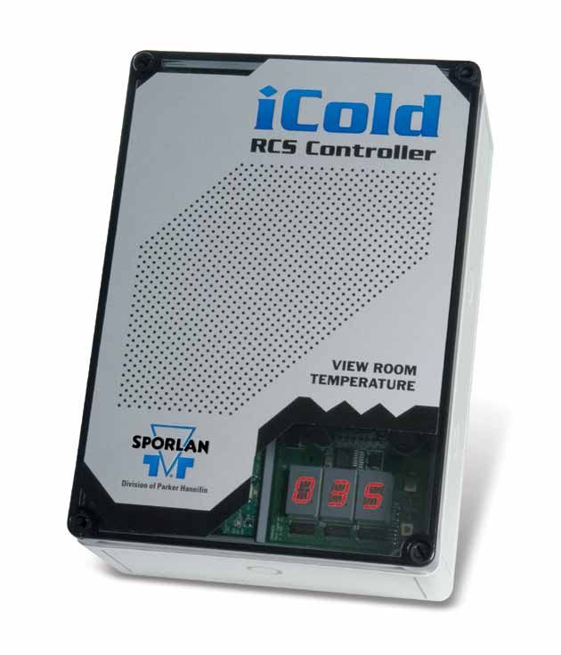
                                                           The integrated display allows the                   probes and a pressure transducer
                                                           end user to have a digital thermostat               to allow the control of superheat,
                                                           mounted to the controlled space.                    defrost, fans, and space temperature.
                                                           The display alternates between the                  Each sensor is provided with a 6.5
                                                           system status and the room tempera-                 ft. (2 m) lead and may be extended
                                                           ture. The display consists of a 3 digit             to 100 ft. (30.5 m) using 18 gage
                                                           alphanumeric display that allows                    shielded twisted pair. Sensor wires
                                                           full configuration of the controller                should never be in the same conduit
                                                           without additional hardware. There                  as high voltage lines (>30V). Care

FOR USE ON REFRIGERATION and/or AIR CONDITIONING SYSTEMS ONLY
Bulletin 100-50-4, September 2010, supersedes Bulletin 100-50-4, September 2007, and all prior publications.
Page 2 / Bulletin 100-50-4

                                                                                  and external alarm. The power sup-

   Specifications
                                                                                  ply for the solenoid should be sized
                                                                                  according to the instructions in
                                                                                  Bulletin 30-10.
   RCS GENERAL SYSTEM                    PRESSURE TRANSDUCER
   SPECIFICATION                         (Suction Pressure)
   Input voltage                         Maximum seal temperature                 Communication
     24 AC/DC VAC (± 10%)                range                                    Communication software (PERC) is
     40 VA minimum                         -40°F to 120°F                         available for free, contact your local
   Operating ambient                     Seal type                                Sales Engineer. The PERC software
   temperature                             Neoprene                               displays all of the setpoints and mea-
     -40°F to 120°F                      Pressure range                           surements in a single view to allow
   Control temperature range               0 to 150 psi                           the user to rapidly configure the
     -20°F to 60°F                       Transducer accuracy                      controller for the application. This
   Control update rate                     % of F.S. 1%                           requires the use of the board’s RS-485
     1 Hz max.                           Supply voltage                           output. The RCS may communicate
   True superheat regulation               5 Volts DC +/- 0.5 VDC                 on site through direct connection to
     +/-2°F                              Output range                             the computer. This requires a con-
   LED Display                             0.5 (0 psi) to                         nection to the PC using an interface
     3 character, 16 element               4.5 (150 psi) Volts DC                 cable like a USB to RS-485, or other
     alphanumeric display                Electrical connection
                                                                                  converter. The controller may also be
                                           Mates with Packard 12065287
                                                                                  accessed remotely through a modem.
   COMMUNICATIONS
                                         THERMISTOR                               Remotely monitoring the controller
   Remote setting and
                                         Nominal                                  allows the technician to diagnose
   monitoring
                                          3,000 ohms at 25°C                      the problem before arriving at the
    RS485
                                          (two button)                            job. This gives the technician the
   BATTERY LIFE                           2,000 ohms at 25°C                      flexibility to monitor the system and
   Real time clock battery                (optical encoder)                       potentially fix the problem without
   backup                                Accuracy                                 requiring a service call.
    >10 years                             -4°F to 122°F = ±1°F
    (during active operation)                                                     Application
                                                                                  The RCS package combines the EEV
should be taken to properly attach       ducer allows the controller to convert   control with many other system
each probe to the location for its       the suction pressure to a saturated      components. Traditional control of
                                         temperature to calculate superheat.      refrigeration equipment has relied
function.
                                                                                  on a piece meal approach. Each
                                                                                  control function is carried out by
The first temperature sensor is
installed on the suction line, with
                                         Relays                                   discrete control components; such
                                         The fan and defrost relays on the        as a defrost time clock, thermostat,
included straps, and the temperature
                                         board can be loaded to 30A in            defrost termination switch, etc.
reading allows the RCS to calculate
                                         normally closed operation and 40A        Recent technological advances have
the superheat. When installing the                                                integrated these functions into a
                                         in the normally open. The fans are
superheat sensor, the same practices                                              single device that is easy to use. The
                                         primarily engaged when the com-
should be followed as installing a                                                RCS is a control solution designed
                                         pressor is running. The fan control
TEV bulb. The sensor should never                                                 to be used with any system utilizing
                                         may be altered by changing the fan
go on the top or bottom of the line.                                              a single condenser and evaporator.
                                         temperature and drain time set-
It should be located on a horizontal     tings. The defrost relay is controlled   This is a reasonably priced alterna-
section of line in the 4 or 8 o’clock    by the defrost settings and may be       tive that allows, for the first time,
position. The second temperature         initiated at a specific time of day.     a single point of reference for all
sensor is used to control the space      Once the time of the first defrost is    control components for these types
temperature. It is also displayed as a   set, the number per day may be set,      of systems. The NEMA 12K enclosure
process variable. This sensor should     determining the number of defrosts       allows the controller to be mounted
be located in the space in a loca-       required will depend on the system.      conveniently in almost any loca-
tion that will not be affected by the                                             tion. The 5 prepositioned knockouts
airstream or any heat source, such as    The board is also equipped with a        provide easy access to the proper
a door. The 0-150 psig pressure trans-   solid state liquid line solenoid relay   locations when wiring the board.
Bulletin 100-50-4 / Page 3

With only the addition of an EEV, the

                                             Service Parts
controller is ready to be installed on
the system. When selecting the EEV,
refer to Bulletin 100-20. This bulletin
gives step by step instructions on the       PART DESCRIPTION                                     PART NUMBER
selection of the valve.                      RCS Controller (board only)                                      953161
                                             Pressure Transducer                                              953091
The selection of the controller is sim-       150 psig, 6.5’ (2 m)
plified due to the controller’s ability      Temperature Sensor
to be configured on site. The 24V             6.5’ (2 m) 3,000 ohm                                         952551
transformer included in the pack-             12’ (4 m) 2,000 ohm                                          952662
age is ready to receive 120V or 230V.        Well Sensor                                                   952795
The power being supplied is simply           Relay Board                                     Available on request
selected at the flip of a switch.

   Dimensions

                                                                      6.5’ (1.98 m)           1.26” (32 mm)

           2.13”                                         Temperature Sensor
         (5.41 cm)                                                                                                  .20”
                                                                                                              (5.08 mm)

                                                                                2.03” max.
                                                                                (51.6 mm)
                                                                           1.40” max.
                                                                           (35.6 mm)                              Ground
                                                                                                                  Supply
                                                                                                                  Voltage
                                                           ø0.67”
                                                         (ø17.0 mm)

      8.75”                                                                                                       Output
   (22.23 cm)
                                                         0.6250” (15.9 mm) across flats
                                                         0.25” SAE female flare with               ø0.95”
                                                         deflator 7/16-20 UNF-2B               (ø24.0 mm) typ.
           6.56”
        (16.66 cm)                                       Pressure Transducer

                                                            0.25”                0.94”
                                                         (6.35 mm)            (23.88 mm)

                                                                                                       0.625”
                                                                                                     (15.88 mm)

                                               Optical
                                                                          1.0”
                                               Encoder                (25.40 mm)
                                   3.25”                                    1.44”
                                 (8.26 cm)                               (36.58 mm)
   RCS Controller Board                                  Well Sensor
Page 4 / Bulletin 100-50-4

   Wiring Schematic
                                                                                                               Fans
             Heaters                                    NC                    NC
                                                                              NO               L2
                                                        NO
                                                                                               L1
                                                                              COM
                                                        COM                                                   Load
                                       L2 L1
                                       L2 L1                                                                                Line
                           Alarm                                                                                       L1
                                                                                                                       L2

                                Orange | Black                                                   Liquid
       ESX    All Others        Yellow | White                                                 Line Valve
       5-Wire 4-Wire               Red | Green
                                 Black | Red
                                  Gray | NA
                                                                                                                Auxiliary Temp.
                                               +A
           RS-485-2                            -B
                                              GRD                                                     Defrost Termination Temp.

           Not used                        +12V                                                                       Room Temp.
                                            +5V
                                             +A                                                         Evaporator Outlet Temp.
           RS-485-1                          -B
                                           GRD
                                                                                       Red          Suction Pressure Transducer
           24 Volt VAC                                                                 Black
                                                                                       Green

                               Transformer*
                                        230
                                        120
                              *Select Voltage

                Stepper EEV
                                                                                                                       Figure 1

Installation                                        Ordering
Instructions                                        Instructions
Installation instructions are available             Each RCS package, Part Number 953170, includes:
for the RCS controller, temperature                 1		 RCS Controller
sensor, pressure transducer and                     1		 Dual Voltage Transformer
monitoring software disk. Additional                3		 Temperature Sensors
product information and updates                     1		 Temperature Transducer
may be found at www.sporlan.com.                    1		 NEMA 12K Enclosure
PRODUCT FORMS
RCS Controller
Form SD-302
Temperature Sensor
Form SD-245
Pressure Transducer
Form SD-245
Monitoring Software Disk
Form SD-303
© 2010 Parker Hannifin Corporation                                                92010 / Bulletin 100-50-4

                                     Parker Hannifin Corporation
                                     Sporlan Division
                                     206 Lange Drive • Washington, MO 63090 USA
                                     phone 636 239 1111 • fax 636 239 9130
                                     www.sporlan.com
You can also read