TECCO / SPIDER systems stabilize slopes using high-tensile wire.
←
→
Page content transcription
If your browser does not render page correctly, please read the page content below
TECCO® / SPIDER® systems
stabilize slopes using
high-tensile wire.

• high-tensile wire mesh
    (tensile strength of at
    least 1770 N/mm2)
•   system can be optimized
    depending on the subsoil
    with several mesh types
•   cost-effective thanks to
    wide nail spacing
•   dimensioning concept
    based on large-scale field
    and model tests
•   small CO2 footprint and
    option to cover with
    natural vegetation

             European Technical Approval
             w w w. e o t a . e u
Ideal protection against slope sliding
    close to the surface.

    Characteristics of high-tensile
    meshes and spiral rope nets:

    • high performance despite
      low weight
    • all components have an
      uniform strength
    • can be installed close to the
      ground even in irregular
      terrain
    • little deformation
    • quick to construct
    • maintenance-free
    • minimal disruption to nature
    • can be covered over quickly
      with natural vegetation
    • permeable to water
    • virtually invisible

2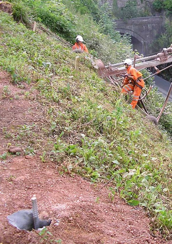
TECCO®SYSTEM 3 versus conventional systems
Advantages over shotcrete walls and
supporting structures made of concrete:
• cost-effective thanks to flexible nail spacing
• no drainage outlets required
• groundwater can circulate freely
• virtually invisible
• no additional strain placed on the slope
• quick and easy to install with no excavation
  work required
• stays flexible during tremors and earthquakes
• closed traffic routes can reopen quickly
• 4–9 x smaller CO2 footprint

Advantages over wire rope nets, hexagonal
meshes and heavy square-mesh nets:
• quicker to install thanks to wide panels that
  can be unrolled
• easier to adapt to uneven terrain
• stronger
• load-bearing performance can be controlled
• easier to tension
• greater flexibility and dimensional stability
• minimal deflection

                                                   3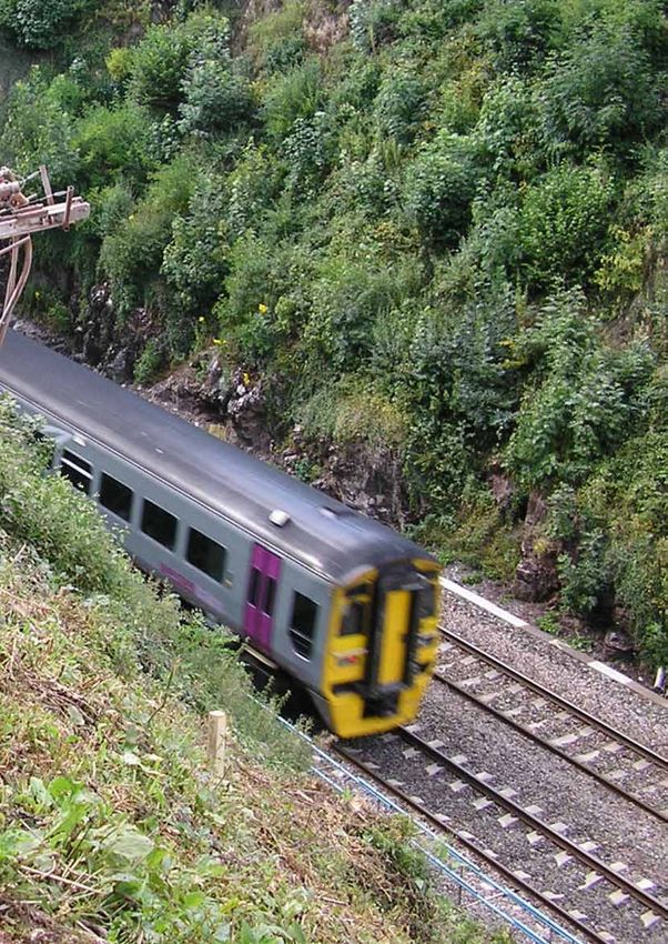
A safe and secure system
    for any type of subsoil.

                                                                    Vegetation matting:
                                                                    TECMAT®
                                                                    • reduces the amount of seed washed away
                                                                    •   stabilizes the topsoil layer

                                               P33 spike plate
                                               • standard version

                                                                    P66 spike plate
                                                                    • optimized nail grid
                                                                    • less deformation

    T3 clip
    • allows panels to be connected securely
    • uses the whole width of the panels

4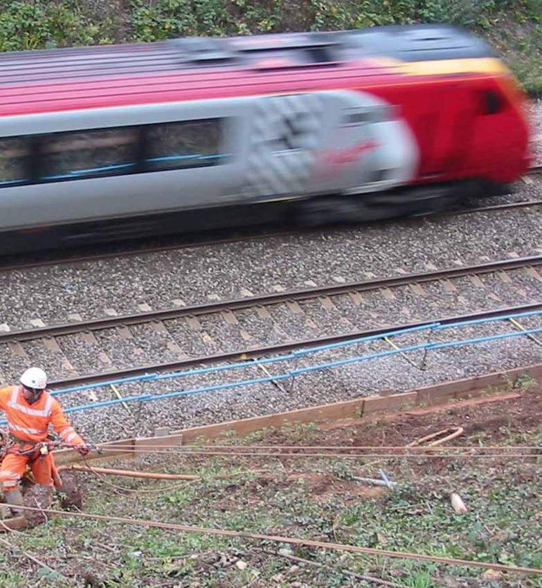
TECCO® SYSTEM3 in
unconsolidated soil
• pre-tensioning optimized to minimize
deformation
• simple to connect with no unnecessary overlaps
• even distribution of forces
• quick to cover with natural vegetation
• freely dimensionable nail grid
• spike plates can be selected based on dimensioning
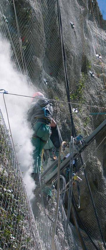
TECCO® SYSTEM3 in rock
• can be installed close to the ground in
any terrain
• freely selectable nail pattern
• very safe working environment as the
mesh can be drilled through
SPIDER® spiral rope net
• spiral rope made from twisted high-tensile
steel wire
• high tensile strength
• can be nailed close to the ground in any terrain
• highly resistant to perforation
• mesh can be drilled through, permitting
the precise positioning of nails on individual
boulders to be secured
5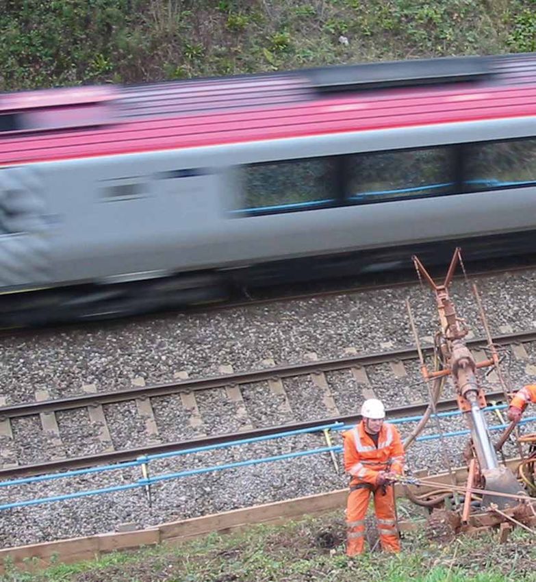
Developed and tested in laboratory
    and large-scale field tests.

    The Bavarian Trade Institute (Landesgewerbeanstalt      tensile strength and load-bearing resistance. Tests
    – LGA) in Nuremberg and other independent               of the mesh links also demonstrated that, thanks to
    testing institutes have confirmed the load-bearing      the TECCO® connection clips, the system has a load-
    performance of the TECCO® SYSTEM 3 in numerous          bearing capacity of 100 %, even at the seams.
    laboratory tests (longitudinal and transverse pulling
    direction, connection clips, perforation with/without
    soil and shearing). In particular, the tests also
    measured the interaction between the mesh, spike
    plate and anchorage and calculated the system’s

    Laboratory tests                                                                                              RUVOLUM® dimensioning
    Quality control:                                        Tensile load parallel to the slope,                   software developed from
    tensile test of the mesh                                concentrated at certain points: Z                     large-scale field tests
                                                                                                                  In cooperation with Bern University of Applied
                                                                                                                  Sciences in Burgdorf, a flat test frame measuring
                                                                                                                  10 x 12 x 1.2 m was filled with gravel, covered with
                                                                                                                  high-tensile TECCO® meshes and anchored into a
                                                                                                                  2.5 x 2.5 m up to 3.5 x 3.5 m grid using spike plates
                                                                                                                  and nails so that the calculations could be verified
                                                                                                                  under as realistic conditions as possible. By gradually
                                                                                                                  increasing the angle of inclination, the tests showed
                                                                                                                  that the mesh can successfully hold back 230 metric
    Perforation test on the mesh parallel                                                                         tons of material at an angle of up to 85 degrees.
    to the nails: P                                                                                               Decisive are the local load transfer of the mesh to the
                                                                                    Z
                                                                                                                  nail and its punching strength at the upper part of the
                                                                                                                  spike plate.

                                                                    P

                                                                                           2•b

                                                                                                                                      www.geobrugg.com/
                                                                                                                                      youtube/TECCO-fullscale

                                                                                                                                      SCAN IT!
6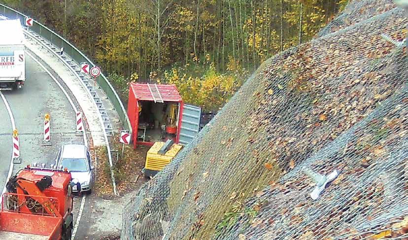
7
RUVOLUM®dimensioning concept:
    Simple planning for increased security.

    Instabilities near the surface
    To help dimension the forces acting on a stabilization    Our studies provide proof of our protection and into
    system, we developed a special program based on           account factors such as:
    geotechnical considerations of equilibrium, which we      • Slippage in the direction of the slope
    make available to planners as an online tool:             • Perforation of the mesh
    http://applications.geobrugg.com                          • Combined load on the nails
                                                              • Shearing of the mesh on the edge of the
                                                                 spike plate

    Two studies: The dimensioning                                                                                    Global stability
    basis underlying the                                                                                             Deploying steel wire mesh to stabilize slopes can
    RUVOLUM® model                                                                                                   also be used to tackle global stability problems.
                                                                                                                     Here, the nails required for deeper-lying slip
    1. Local instabilities between the nails:                                                                        surfaces are also dimensioned using convention-
    Where local instabilities also occur between the nails,                                                          al methods and the results compared with the
    we calculate the absorption capacity of the entire                                                               RUVOLUM® calculation.
    «nailing/mesh covering» system.

    2. Instabilities near the surface and parallel
    to the slope:
    If the surface layer is in danger of slipping against a
    firmer subsoil, the nails must prevent it from breaking
    up. The number and configuration of the nails must be
    dimensioned according to the forces calculated.

8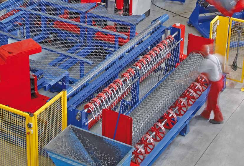
A cost-effective solution

The TECCO® SYSTEM 3 and SPIDER® system can pro-
vide the same level of protection as a conventional
protective covering but using only half as many
nails. This can significantly reduce the total project
                                                         Total project costs

costs and the installation time.

                          Mesh costs

                                                                                 Conventional
                        Nailing costs                                          flexible systems
                                                                                                  TECCO® G65/2   TECCO® G65/3   TECCO® G65/4
                                                                                                                                               9
Technical data.

      SPECIFICATION                                                                                                                                        TECCO® G65/2
      ETA certificate no.                                                                                                                                  ETA-13/0404

      CE no.                                                                                                                                               1301-CPD-0898

      Wire diameter                                                                                                                                        2.0 mm

      Spiral wire diameter 1 x 3                                                                                                                           -

      Tensile strength of wire                                                                                                                             ≥ 1770 N/mm2

      Corrosion protection                                                                                                                                 GEOBRUGG ULTRACOATING®

      Mesh width                                                                                                                                           65 mm

      Number of meshes, top to bottom                                                                                                                      7.0 pcs/m

      Number of meshes, side to side                                                                                                                       12.0 pcs/m

      Tensile strength of mesh, horizontally (for the purposes of comparison only – not for use in dimensioning)                                           ≥ 65 kN/m in accordance with LGA test report 01/2014

      Weight per m2                                                                                                                                        0.74 kg/m2

      Roll edges                                                                                                                                           Mesh ends knotted and twisted

      Roll width                                                                                                                                           3.5 m

      Roll length                                                                                                                                          40 m

      Total area per roll                                                                                                                                  140 m2

      Weight per roll                                                                                                                                      104 kg

      Load-bearing resistance for load transfer (for use in dimensioning)                                                                                  P33 spike plate

      Load-bearing resistance of mesh to tensile loads parallel to the slope and concentrated at certain points (ZR)                                       10 kN

      Load-bearing resistance of mesh to perforations parallel to the nails (2 · PR )                                                                      80 kN

      Load-bearing resistance of the mesh to shearing at the top edge of the spike plate (PR )                                                             40 kN

      Service life*
      Climatic category C2: temperate, rural areas in accordance with EN ISO 12944-2 and ISO 9223                                                          > 120 years

     * The standards EN ISO 12944-2 and EN 12500 stipulate ranges for rates of zinc erosion in g/m2/year for each of the climatic categories C1 to C5. This allows the theoretical service life assuming proper use to be calculated.

10
TECCO® G65/3 TECCO® G65/4 SPIDER® S3-130
ETA-13/0405 ETA-13/0406 ETA-13/0477
1301-CPD-0899 1301-CPD-0900 1301-CPD-0913
3.0 mm 4.0 mm 3.0 mm
- - 6.5 mm
≥ 1770 N/mm2 ≥ 1770 N/mm2 ≥ 1770 N/mm2
GEOBRUGG SUPERCOATING® GEOBRUGG SUPERCOATING® GEOBRUGG SUPERCOATING®
65 mm 63 mm 143 mm
7.0 pcs/m 7.2 pcs/m 3.3 pcs/m
12.0 pcs/m 12.0 pcs/m 5.6 pcs/m
≥ 150 kN/m in accordance with LGA test report 01/2014 ≥ 250 kN/m in accordance with LGA test report 01/2014 ≥ 220 kN/m in accordance with LGA test report 01/2014
1.65 kg/m2 3.3 kg/m2 2.60 kg/m2
Mesh ends knotted and twisted Mesh ends knotted and twisted Mesh ends knotted and twisted
3.5 m 3.5 m 3.5 m
30 m 20 m 20 m
105 m2 70 m2 70 m2
175 kg 231 kg 182 kg
P33 / P66 spike plates P33 / P66 spike plates P33 / P66 spike plates
30 kN / 45 kN 50 kN / 75 kN 45 kN/ 70 kN
180 kN / 240 kN 280 kN / 370 kN 230 kN / 300 kN
90 kN / 120 kN 140 kN / 185 kN 115 kN / 150 kN
90–120 years 90–120 years 90–120 years
SUPERCOATING® ensures at least three times (EN 1993-1-11, AS/NZS 4534) and ULTRACOATING® six times longer service lives compared to wire galvanized in a conventional manner.
11Geobrugg, a reliable partner.
Our engineers and partners analyze the situation support if required – from installation right through to appropriately. In addition, events that exceed the
together with you and then, working together with final acceptance of the structure. system’s calculated absorption capacity may cause
local engineering firms, present their solutions. damage. The use of non-original parts as well as
Painstaking planning is not the only thing you can Product liability severe corrosion, such as might be caused by
expect from us, however; since we have our own Rockfalls, landslips, debris flows, shallow landslides environmental pollution, can reduce the level of
production plants on four continents, we can offer not and avalanches are natural events and therefore protection provided.
only short delivery times but also the best possible cannot be calculated. For this reason, it is impossible to
customer service right on your doorstep. To ensure determine or guarantee absolute safety for persons
your project runs smoothly, we deliver pre-assembled and property using scientific methods. This means that,
and clearly labeled system components right to the to provide the desired level of protection, protective
construction site. Here, we can also provide technical systems must be monitored and serviced regularly and
Geobrugg AG
Geohazard Solutions
1.102.05.EN.1408
Aachstrasse 11 • CH-8590 Romanshorn • Switzerland
Phone +41 71 466 81 55 • Fax +41 71 466 81 50
www.geobrugg.com • info@geobrugg.com
A company of the BRUGG Group
ISO 9001 certifiedYou can also read