In-flight performance of the LEKIDs of the OLIMPO experiment - Infn
←
→
Page content transcription
If your browser does not render page correctly, please read the page content below
Science Case
                                  OLIMPO LEKIDs
                              In–flight performance
                                        Conclusions

                                                             In–flight performance of the LEKIDs
                                                                  of the OLIMPO experiment
                                                                            Alessandro Paiella
                                                                     for the OLIMPO detector team

18th International Workshop on Low Temperature Detectors
July 22–26, 2019, Milano, Italy

LTD18, 24 July 2019               Alessandro Paiella   In–flight performance of the LEKIDs of the OLIMPO experiment   1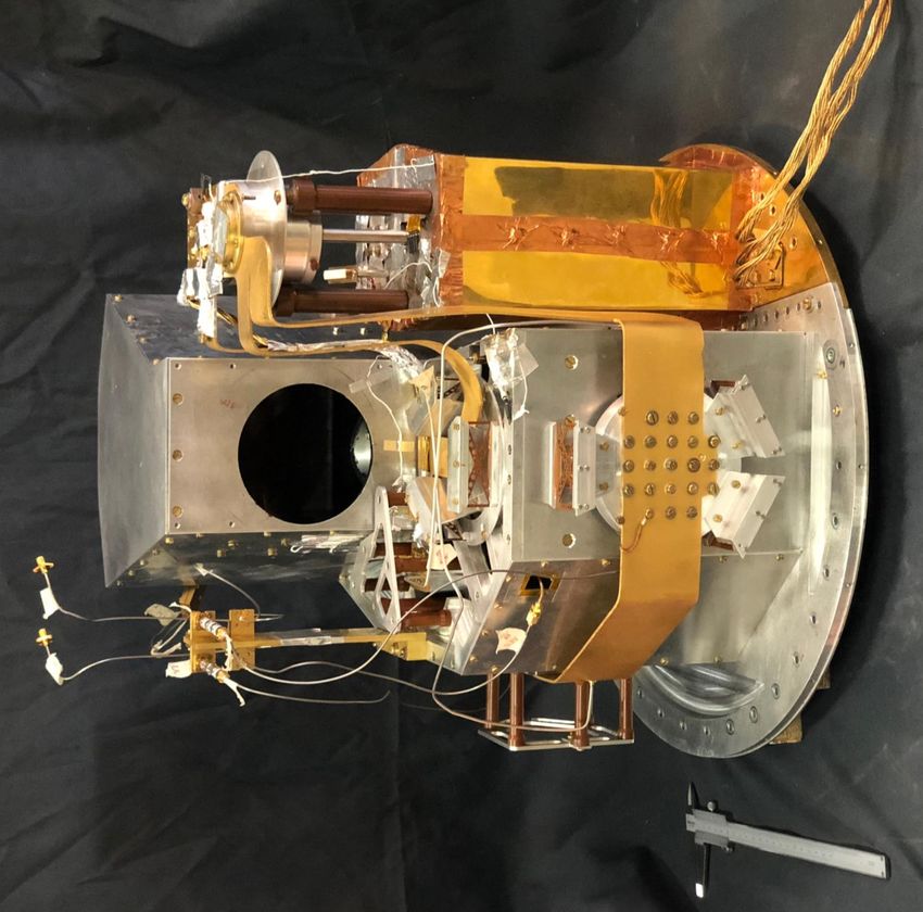
Science Case
                                                           Galaxy Clusters
                                     OLIMPO LEKIDs
                                                           Sunyaev–Zel’dovich effect
                                 In–flight performance
                                                           OLIMPO
                                           Conclusions

 Galaxy Clusters
     Galaxy Clusters are the largest gravitationally bound structures in the Universe, which can be observed across
     the entire electromagnetic spectrum.
     The strength of observing them at mm wavelengths lies in the possibility to study the low density parts, their
     periphery, and the filaments of ionized matter connecting clusters.

                                                                                                        LFI & HFI Consortia (Planck image);
                                                                                                        The Coma cluster. Image credits:

                                                                                                        MPI (ROSAT image);
                                                                                                        DSS2 (visible image)
LTD18, 24 July 2019                  Alessandro Paiella   In–flight performance of the LEKIDs of the OLIMPO experiment                        2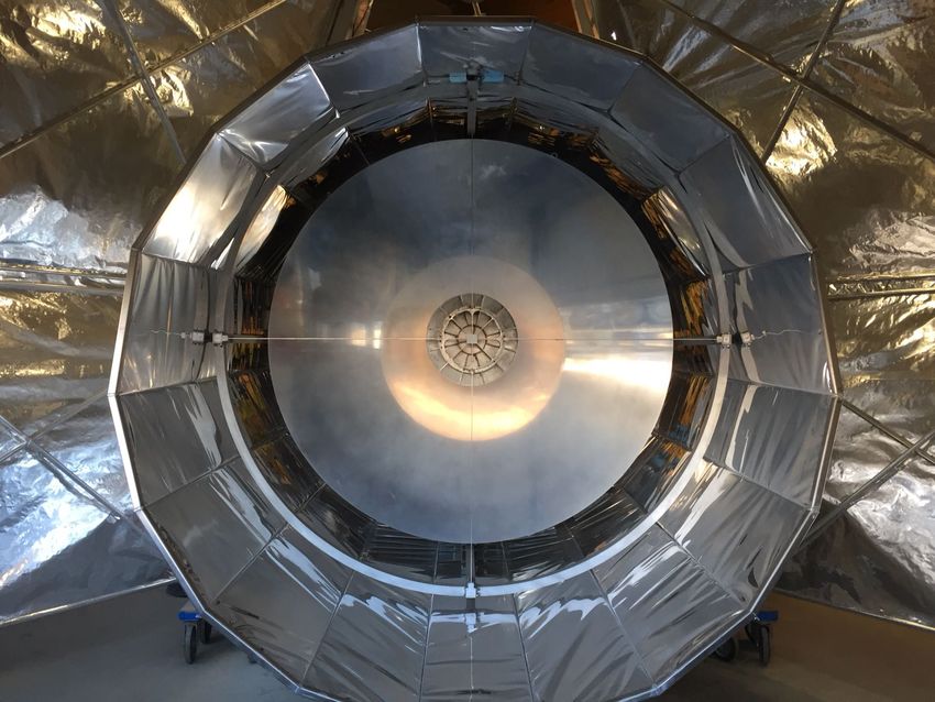
Science Case
                                                           Galaxy Clusters
                                     OLIMPO LEKIDs
                                                           Sunyaev–Zel’dovich effect
                                 In–flight performance
                                                           OLIMPO
                                           Conclusions

 Sunyaev–Zel’dovich effect
     The way to study galaxy clusters at mm wavelengths is through the

                                                                                                                                                                         J. Erler et al. 2018,MNRAS
     Sunyaev–Zel’dovich (SZ) effect of the CMB photons.
     CMB photons crossing the hot gas of clusters of galaxies, acquire
     energy from charged scatterers (via inverse Compton), and their
     spectrum is perturbed with a very distinct spectral signature.

                            A2319 seen by Planck

                                                                                                                        30   44   70 100 143 217   353 545   857

                                                                                                                                                                     The am atmospheric model
                                                                                                                  1.0

                                                                                       Atmospheric Transmission
                                                                                                                  0.8

     A spectral measurement of CMB anisotropy can vastly improve the                                              0.6
     accuracy, allowing efficient, unbiased separation of the CMB and SZ
     components from all other components in the same LOS (at least 8                                             0.4

     independent points);
                                                                                                                  0.2
     It can be done only from space or the stratosphere due to
     atmospheric opacity and noise.                                                                               0.0
                                                                                                                        30           100         300          1000
                                                                                                                                    Frequency [GHz]
LTD18, 24 July 2019                  Alessandro Paiella   In–flight performance of the LEKIDs of the OLIMPO experiment                                                                                3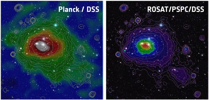
Science Case
Galaxy Clusters
OLIMPO LEKIDs
Sunyaev–Zel’dovich effect
In–flight performance
OLIMPO
Conclusions
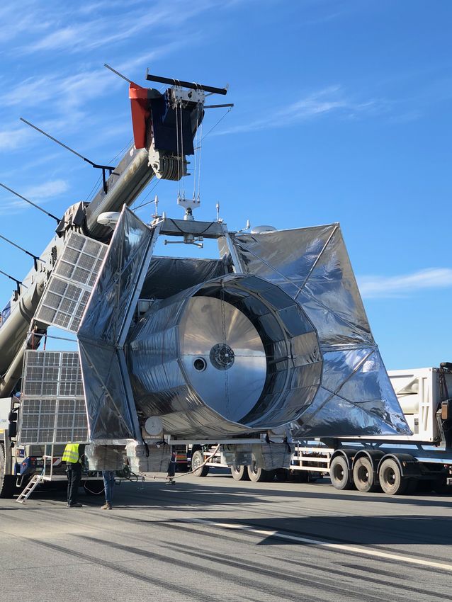
OLIMPO (Osservatorio nel Lontano Infrarosso Montato su Pallone Orientabile)
The OLIMPO experiment is a first attempt at
spectroscopic measurements of CMB anisotropy.
OLIMPO uses the CMB as a backlight to study the
largest structures in the Universe.
OLIMPO is a large balloon-borne observatory
with a 2.6 m aperture telescope;
with 4 horn-coupled LEKID arrays, centered at
150, 250, 350 and 460 GHz, matching the
negative, zero, and positive regions of the SZ
spectrum,
cooled to 0.3 K by a 3 He refrigerator in a wet
LN2 +L4 He cryostat;
with a plug–in room–temperature differential
Fourier transform spectrometer (DFTS);
with a custom attitude control system (ACS),
which allow to point the telescope in the
direction of the selected galaxy clusters with
arcmin accuracy.
For more details see http://olimpo.roma1.infn.it
LTD18, 24 July 2019 Alessandro Paiella In–flight performance of the LEKIDs of the OLIMPO experiment 4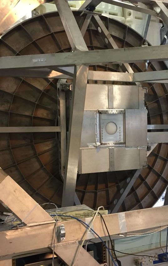
Science Case
                                                            Galaxy Clusters
                                      OLIMPO LEKIDs
                                                            Sunyaev–Zel’dovich effect
                                  In–flight performance
                                                            OLIMPO
                                            Conclusions

 OLIMPO (Osservatorio nel Lontano Infrarosso Montato su Pallone Orientabile)
       The OLIMPO experiment is a first attempt at
       spectroscopic measurements of CMB anisotropy.
       OLIMPO uses the CMB as a backlight to study the
       largest structures in the Universe.
       OLIMPO is a large balloon-borne observatory
             with a 2.6 m aperture telescope;
             with 4 horn-coupled LEKID arrays, centered at
             150, 250, 350 and 460 GHz, matching the
             negative, zero, and positive regions of the SZ
             spectrum,
             cooled to 0.3 K by a 3 He refrigerator in a wet
             LN2 +L4 He cryostat;
             with a plug–in room–temperature differential
             Fourier transform spectrometer (DFTS);
             with a custom attitude control system (ACS),
             which allow to point the telescope in the
             direction of the selected galaxy clusters with
             arcmin accuracy.
       For more details see http://olimpo.roma1.infn.it

LTD18, 24 July 2019                   Alessandro Paiella   In–flight performance of the LEKIDs of the OLIMPO experiment   4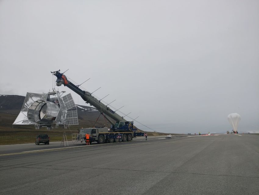
Science Case
                                                            Galaxy Clusters
                                      OLIMPO LEKIDs
                                                            Sunyaev–Zel’dovich effect
                                  In–flight performance
                                                            OLIMPO
                                            Conclusions

 OLIMPO (Osservatorio nel Lontano Infrarosso Montato su Pallone Orientabile)
       The OLIMPO experiment is a first attempt at
       spectroscopic measurements of CMB anisotropy.
                                                                                                                   He fridge
                                                                                                                   3

       OLIMPO uses the CMB as a backlight to study the
       largest structures in the Universe.                                    250 GHz array

       OLIMPO is a large balloon-borne observatory
             with a 2.6 m aperture telescope;                                 460 GHz array
             with 4 horn-coupled LEKID arrays, centered at
             150, 250, 350 and 460 GHz, matching the
             negative, zero, and positive regions of the SZ                   350 GHz array

             spectrum,
             cooled to 0.3 K by a 3 He refrigerator in a wet
             LN2 +L4 He cryostat;
             with a plug–in room–temperature differential
             Fourier transform spectrometer (DFTS);
             with a custom attitude control system (ACS),
             which allow to point the telescope in the
             direction of the selected galaxy clusters with                             150 GHz array
                                                                                                            gold-plated ETP
             arcmin accuracy.                                                                               copper link

       For more details see http://olimpo.roma1.infn.it

LTD18, 24 July 2019                   Alessandro Paiella   In–flight performance of the LEKIDs of the OLIMPO experiment        4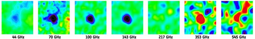
Science Case
                                                            Galaxy Clusters
                                      OLIMPO LEKIDs
                                                            Sunyaev–Zel’dovich effect
                                  In–flight performance
                                                            OLIMPO
                                            Conclusions

 OLIMPO (Osservatorio nel Lontano Infrarosso Montato su Pallone Orientabile)
       The OLIMPO experiment is a first attempt at
       spectroscopic measurements of CMB anisotropy.
       OLIMPO uses the CMB as a backlight to study the
       largest structures in the Universe.
       OLIMPO is a large balloon-borne observatory
             with a 2.6 m aperture telescope;
             with 4 horn-coupled LEKID arrays, centered at
             150, 250, 350 and 460 GHz, matching the
             negative, zero, and positive regions of the SZ
             spectrum,
             cooled to 0.3 K by a 3 He refrigerator in a wet
             LN2 +L4 He cryostat;
             with a plug–in room–temperature differential
             Fourier transform spectrometer (DFTS);
             with a custom attitude control system (ACS),
             which allow to point the telescope in the
             direction of the selected galaxy clusters with
             arcmin accuracy.
       For more details see http://olimpo.roma1.infn.it

LTD18, 24 July 2019                   Alessandro Paiella   In–flight performance of the LEKIDs of the OLIMPO experiment   4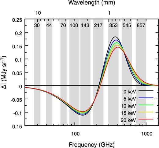
Science Case
                                                            Galaxy Clusters
                                      OLIMPO LEKIDs
                                                            Sunyaev–Zel’dovich effect
                                  In–flight performance
                                                            OLIMPO
                                            Conclusions

 OLIMPO (Osservatorio nel Lontano Infrarosso Montato su Pallone Orientabile)
       The OLIMPO experiment is a first attempt at
       spectroscopic measurements of CMB anisotropy.
       OLIMPO uses the CMB as a backlight to study the
       largest structures in the Universe.                                     Azimuth
                                                                                Pivot
       OLIMPO is a large balloon-borne observatory
             with a 2.6 m aperture telescope;
             with 4 horn-coupled LEKID arrays, centered at                      Star Sensor
             150, 250, 350 and 460 GHz, matching the                                                            Sun Sensors

             negative, zero, and positive regions of the SZ
             spectrum,
             cooled to 0.3 K by a 3 He refrigerator in a wet
             LN2 +L4 He cryostat;
             with a plug–in room–temperature differential
             Fourier transform spectrometer (DFTS);                            Elevation
             with a custom attitude control system (ACS),                       Motor

             which allow to point the telescope in the
             direction of the selected galaxy clusters with
             arcmin accuracy.
                                                                                              ACS/NAV PCs
       For more details see http://olimpo.roma1.infn.it

LTD18, 24 July 2019                   Alessandro Paiella   In–flight performance of the LEKIDs of the OLIMPO experiment       4
Science Case
                                                             Galaxy Clusters
                                       OLIMPO LEKIDs
                                                             Sunyaev–Zel’dovich effect
                                   In–flight performance
                                                             OLIMPO
                                             Conclusions

 OLIMPO flight
     OLIMPO was launched from the Longyearbyen airport (78 ◦ N), in Svalbard
     Islands, at 07:07 GMT on July 14th , 2018.
     In–flight analysis: measurements carried out in the first day of the flight,
     when the fast (500 kbps) bidirectional LOS telemetry was active.

                                                                                                                           Fast Forward 4×
LTD18, 24 July 2019                    Alessandro Paiella   In–flight performance of the LEKIDs of the OLIMPO experiment                     5
sub
is schematised by a resistance, representing the absorber impedance, Zind , eq. (4.1). It is
Science Case
OLIMPO LEKIDs Generalities
necessary to specify
In–flight performance Ground thePerformance
port of the system and the frequency range over which the simulation
has to be run. The software then evaluates the S11 parameter of the system from which it is
Conclusions
possible to find the absorber absorbance, A, as
OLIMPO LEKIDs
A = 1 ≠ |S11 |2 . (4.11)
150 GHz 250 GHz 350 GHz 460 GHz
Absorber/Inductor: IV order Hilbert in AlThe system has only one port because of the presence of a perfect backshort, which reflects
30 nm thick (Tc = 1.31 K, R2 = 1.21 Ω/2);all the radiation coming at its surface.
Fig. 4.15 shows two sketches of the front-illuminated (left panel) and of the back-illuminated
Radiation coupling: front–illuminated via (right panel) configuration. In the front-illuminated configuration, the incoming radiation
single–mode (flared) circular waveguide; is directly absorbed by the absorber, and the non-absorbed radiation is reflected by the
backshort, after passing through the substrate, in order to be absorbed in a second attempt.
Substrate, number of detectors & resonantIn the back-illuminated configuration, the radiation is absorbed by the absorber after passing
frequencies: through the substrate, and, also in this case, the non-absorbed radiation is reflected by the
backshort in order to be absorbed in a second attempt. As we already said in subsec. 4.1.1,
Channel Si wafer νr in the back-illuminated configuration, since the radiation passes through the substrate before
# being absorbed, the inductive section must match a different impedance with respect to the
[GHz] d[00 ] × t [µm] [MHz]
front-illuminated case. Moreover, in the two configurations, the distance between the absorber
and the backshort is different because of the different material between them: dielectric
substrate for the front illumination, and vacuum for the back illumination.
Incoming
Electrical coupling: via capacitors to a photons
50 Ω–matched microstrip feedline and to
the ground, and such that Qc ∼ 15 000.
Absorber
More details in A. Paiella et al., JCAP Substrate
2019. Backshort
LTD18, 24 July 2019 Figure 4.15.:
Alessandro Paiella Sketches of
In–flight the front-illuminated
performance of the(left panel) andofofthe
LEKIDs the back-illuminated (right panel)
OLIMPO experiment 6sub
is schematised by a resistance, representing the absorber impedance, Zind , eq. (4.1). It is
Science Case
OLIMPO LEKIDs Generalities
necessary to specify
In–flight performance Ground thePerformance
port of the system and the frequency range over which the simulation
has to be run. The software then evaluates the S11 parameter of the system from which it is
Conclusions
possible to find the absorber absorbance, A, as
OLIMPO LEKIDs
A = 1 ≠ |S11 |2 . (4.11)
150 GHz 250 GHz 350 GHz 460 GHz
Absorber/Inductor: IV order Hilbert in AlThe system has only one port because of the presence of a perfect backshort, which reflects
30 nm thick (Tc = 1.31 K, R2 = 1.21 Ω/2);all the radiation coming at its surface.
Fig. 4.15 shows two sketches of the front-illuminated (left panel) and of the back-illuminated
Radiation coupling: front–illuminated via (right panel) configuration. In the front-illuminated configuration, the incoming radiation
single–mode (flared) circular waveguide; is directly absorbed by the absorber, and the non-absorbed radiation is reflected by the
backshort, after passing through the substrate, in order to be absorbed in a second attempt.
Substrate, number of detectors & resonantIn the back-illuminated configuration, the radiation is absorbed by the absorber after passing
frequencies: through the substrate, and, also in this case, the non-absorbed radiation is reflected by the
backshort in order to be absorbed in a second attempt. As we already said in subsec. 4.1.1,
Channel Si wafer νr in the back-illuminated configuration, since the radiation passes through the substrate before
# being absorbed, the inductive section must match a di erent impedance with respect to the
[GHz] d[00 ] × t [µm] [MHz]
front-illuminated case. Moreover, in the two configurations, the distance between the absorber
150 3 × 135 19 + 4 [146; 267] and the backshort is di erent because of the di erent material between them: dielectric
250 3 × 100 37 + 2 [150; 335] substrate for the front illumination, and vacuum for the back illumination.
350 2 × 310 23 + 2 [362; 478]
460 2 × 135 41 + 2 [288; 487]
Incoming 150 GHz 460 GHz
Electrical coupling: via capacitors to a photons
50 Ω–matched microstrip feedline and to
the ground, and such that Qc ∼ 15 000. 3’’ 2’’
Absorber
More details in A. Paiella et al., JCAP Substrate
2019. Backshort
LTD18, 24 July 2019 Figure 4.15.:
Alessandro Paiella Sketches of
In–flight the front-illuminated
performance of the(left panel) andofofthe
LEKIDs the back-illuminated (right panel)
OLIMPO experiment 6sub
is schematised by a resistance, representing the absorber impedance, Zind , eq. (4.1). It is
Science Case
OLIMPO LEKIDs Generalities
necessary to specify
In–flight performance Ground thePerformance
port of the system and the frequency range over which the simulation
has to be run. The software then evaluates the S11 parameter of the system from which it is
Conclusions
possible to find the absorber absorbance, A, as
OLIMPO LEKIDs
A = 1 ≠ |S11 |2 . (4.11)
150 GHz 250 GHz 350 GHz 460 GHz
Absorber/Inductor: IV order Hilbert in AlThe system has only one port because of the presence of a perfect backshort, which reflects
30 nm thick (Tc = 1.31 K, R2 = 1.21 Ω/2);all the radiation coming at its surface.
Fig. 4.15 shows two sketches of the front-illuminated (left panel) and of the back-illuminated
Radiation coupling: front–illuminated via (right panel) configuration. In the front-illuminated configuration, the incoming radiation
single–mode (flared) circular waveguide; is directly absorbed by the absorber, and the non-absorbed radiation is reflected by the
backshort, after passing through the substrate, in order to be absorbed in a second attempt.
Substrate, number of detectors & resonantIn the back-illuminated configuration, the radiation is absorbed by the absorber after passing
frequencies: through the substrate, and, also in this case, the non-absorbed radiation is reflected by the
backshort in order to be absorbed in a second attempt. As we already said in subsec. 4.1.1,
Channel Si wafer νr in the back-illuminated configuration, since the radiation passes through the substrate before
# being absorbed, the inductive section must match a different impedance with respect to the
[GHz] d[00 ] × t [µm] [MHz]
front-illuminated case. Moreover, in the two configurations, the distance between the absorber
150 3 × 135 19 + 4 [146; 267] and the backshort is different because of the different material between them: dielectric
250 3 × 100 37 + 2 [150; 335] substrate for the front illumination, and vacuum for the back illumination.
350 2 × 310 23 + 2 [362; 478]
460 2 × 135 41 + 2 [288; 487]
Incoming 250 GHz 350 GHz
Electrical coupling: via capacitors to a photons
50 Ω–matched microstrip feedline and to
the ground, and such that Qc ∼ 15 000. 3’’ 2’’
Absorber
More details in A. Paiella et al., JCAP Substrate
2019. Backshort
LTD18, 24 July 2019
Figure 4.15.:
Alessandro Paiella
Sketches of the front-illuminated (left panel) and of the back-illuminated (right panel)
In–flight performance of the LEKIDs of the OLIMPO experiment 6sub
is schematised by a resistance, representing the absorber impedance, Zind , eq. (4.1). It is
Science Case
OLIMPO LEKIDs Generalities
necessary to specify
In–flight performance Ground thePerformance
port of the system and the frequency range over which the simulation
has to be run. The software then evaluates the S11 parameter of the system from which it is
Conclusions
possible to find the absorber absorbance, A, as
OLIMPO LEKIDs
A = 1 ≠ |S11 |2 . (4.11)
150 GHz 250 GHz 350 GHz 460 GHz
Absorber/Inductor: IV order Hilbert in AlThe system has only one port because of the presence of a perfect backshort, which reflects
30 nm thick (Tc = 1.31 K, R2 = 1.21 Ω/2);all the radiation coming at its surface.
Fig. 4.15 shows two sketches of the front-illuminated (left panel) and of the back-illuminated
Radiation coupling: front–illuminated via (right panel) configuration. In the front-illuminated configuration, the incoming radiation
single–mode (flared) circular waveguide; is directly absorbed by the absorber, and the non-absorbed radiation is reflected by the
backshort, after passing through the substrate, in order to be absorbed in a second attempt.
Substrate, number of detectors & resonantIn the back-illuminated configuration, the radiation is absorbed by the absorber after passing
frequencies: through the substrate, and, also in this case, the non-absorbed radiation is reflected by the
backshort in order to be absorbed in a second attempt. As we already said in subsec. 4.1.1,
Channel Si wafer νr in the back-illuminated configuration, since the radiation passes through the substrate before
# being absorbed, the inductive section must match a different impedance with respect to the
[GHz] d[00 ] × t [µm] [MHz]
front-illuminated case. Moreover, in the two configurations, the distance between the absorber
150 3 × 135 19 + 4 [146; 267] and the backshort is different because of the different material between them: dielectric
250 3 × 100 37 + 2 [150; 335] substrate for the front illumination, and vacuum for the back illumination.
350 2 × 310 23 + 2 [362; 478]
460 2 × 135 41 + 2 [288; 487]
Incoming 250 GHz 350 GHz
Electrical coupling: via capacitors to a photons
50 Ω–matched microstrip feedline and to
the ground, and such that Qc ∼ 15 000. 3’’ 2’’
Absorber
More details in A. Paiella et al., JCAP Substrate
2019. Backshort
LTD18, 24 July 2019
Figure 4.15.:
Alessandro Paiella
Sketches of the front-illuminated (left panel) and of the back-illuminated (right panel)
In–flight performance of the LEKIDs of the OLIMPO experiment 6Science Case
OLIMPO LEKIDs Generalities
In–flight performance Ground Performance
Conclusions
Ground Performance (A. Paiella et al., JCAP 2019)
1.0 1.0 1.0 1.0
150 GHz 250 GHz 350 GHz 460 GHz
0.8 0.8 0.8 0.8
Normalized spectrum
Normalized spectrum
Normalized spectrum
Normalized spectrum
0.6 0.6 0.6 0.6
0.4 0.4 0.4 0.4
0.2 0.2 0.2 0.2
0.0 0.0 0.0 0.0
120 130 140 150 160 170 180 200 250 300 320 330 340 350 360 370 380 400 420 440 460 480 500 520
Frequency [GHz] Frequency [GHz] Frequency [GHz] Frequency [GHz]
Channel FWHM Rel Rop ε = Rop /Rel NEP NET√RJ
Active Pixels √
[GHz] [GHz] [rad/pW] [rad/pW] % aW/ Hz µK s
150 16 + 4 (87%) 25 1.4 ± 0.1 0.24 ± 0.04 > 18 ± 3 178 ± 27 182 ± 27
250 32 + 2 (87%) 90 1.8 ± 0.4 0.16 ± 0.01 >9±2 879 ± 132 250 ± 38
350 21 + 2 (92%) 30 2.8 ± 0.1 0.29 ± 0.03 > 10 ± 1 289 ± 43 247 ± 37
460 41 + 2 (100%) 60 4.2 ± 0.2 0.16 ± 0.04 >4±1 771 ± 116 329 ± 49
LTD18, 24 July 2019 Alessandro Paiella In–flight performance of the LEKIDs of the OLIMPO experiment 7Science Case Tuning
OLIMPO LEKIDs Background and Temperature variations
In–flight performance Calibration Lamp
Conclusions Cosmic Ray data contamination
Tuning (S. Masi et al., JCAP 2019)
1.0 data
1.0
fit
In–flight, T = 302 mK, e = 15 deg
Normalized Amplitude
0.8 In–flight, T = 303 mK, e = 15 deg
0.5
In–flight, T = 304 mK, e = 15 deg
Normalized Q
In–flight, T = 310 mK, e = 15 deg
0.6 In–flight, T = 316 mK, e = 15 deg
0.0
Ground, T = 305 mK, e = 3 deg
0.4
−0.5
0.2
Example: pixel #6 of the
−1.0 150 GHz array.
0.0 Performed during the first
−1.0 −0.5 0.0 0.5 1.0 191.30 191.32 191.34 191.36 191.38 191.40
hour of flight.
Normalized I Bias Frequency [MHz]
LTD18, 24 July 2019 Alessandro Paiella In–flight performance of the LEKIDs of the OLIMPO experiment 8Science Case Tuning
OLIMPO LEKIDs Background and Temperature variations
In–flight performance Calibration Lamp
Conclusions Cosmic Ray data contamination
Background and Temperature variations (S. Masi et al., JCAP 2019)
2 150 GHz dark 9 150 GHz edge 1 460 GHz edge 1
6 s < t < 10 s insertion of the (room–T ) DFTS
150 GHz dark 17 150 GHz central 460 GHz central through a moving relay mirror, which
1 460 GHz dark 25 150 GHz edge 2 460 GHz edge 2
460 GHz dark 41 introduces the DFTS optical system in the
optical path between the telescope and the
0
cryostat.
Phase [rad]
All the optically active pixels react to the
−1
radiative background change, which
−2 gradually illuminates the entire array.
The dark pixels do not respond.
−3 t ∼ 9 s all the dark pixels react and their
response is coherent and smaller: thermal.
−4
We estimated the temperature variation of
−5 the arrays: 7 mK for the 150 and 250 GHz
Temp. [mK]
297
0 5 10 15 20 25 30
arrays, 10 mK for the 350 GHz array and
295 Time [GHz] 14 mK for the 460 GHz array.
293 t > 14 s all detectors outputs remain stable after
the insertion of the relay mirror is completed.
0 5 10 15 20 25 30
Time [s]
LTD18, 24 July 2019 Alessandro Paiella In–flight performance of the LEKIDs of the OLIMPO experiment 9Science Case Tuning
OLIMPO LEKIDs Background and Temperature variations
In–flight performance Calibration Lamp
Conclusions Cosmic Ray data contamination
Calibration Lamp
The calibration lamp is composed of
350GHz
array 150GHz a resistor heating, from 1.6 K to 25 K,
array
an absorbing surface (emissivity 28%),
in an integrating cavity coupled to a
460GHz array
Winston cone (efficiency 50%).
5th
250GHz
array
Window It is placed at the center of the Lyot stop
of the OLIMPO Offner reimaging system
(250K)
mirror 4th
Mirror
with
and has an aperture which fills the 5% of
Calibration the Lyot stop area.
Lamp
Its emission illuminates with an
approximately parallel beam all the
detectors, with a maximum variation of a
3rd factor 2 of the illumination level across
mirror
0.3K fridge IF each focal plane surface.
As a result, its 25 K blackbody emission is
diluted by a factor of the order of ∼150 to
1.6K bottom
cover
∼300 depending on the position of the
30K bottom
cover
77K bottom
cover pixels in the focal plane.
LTD18, 24 July 2019 Alessandro Paiella In–flight performance of the LEKIDs of the OLIMPO experiment 10Science Case Tuning
OLIMPO LEKIDs Background and Temperature variations
In–flight performance Calibration Lamp
Conclusions Cosmic Ray data contamination
Calibration Lamp (S. Masi et al., JCAP 2019)
We used the calibration lamp to estimate the in–flight
performance. Channel photon–noise NET√RJ
Ng /Nf √
We normalized the ground and in–flight calibration lamp [GHz] NETRJ µK s µK s
signals to the same value, transferring all the information
in the noise. 150 2 70 91 ± 18
250 8 30 31 ± 6
We obtained in–flight performance very close to be 350 3.5 80 71 ± 14
photon–noise limited for all the arrays.
460 4.5 90 73 ± 15
1.4
13 17 14 10 2 22 0.030 Ground, el = 5 deg
20 6 7 15 9 3 (dark) In–flight, el = 5 deg
#21 of the 350 GHz array
1.2 8 16 18 1 4 12 (dark)
11 5 0 21 19 0.025
1.0
350 GHz array
0.020
0.8
Phase [rad]
Phase [rad]
0.015
0.6
0.010
0.4
0.005
0.2
0.000
0.0
−0.005
−0.2
0 5 10 15 20 0 2 4 6 8 10
Time [s] Time [s]
LTD18, 24 July 2019 Alessandro Paiella In–flight performance of the LEKIDs of the OLIMPO experiment 11Science Case Tuning
OLIMPO LEKIDs Background and Temperature variations
In–flight performance Calibration Lamp
Conclusions Cosmic Ray data contamination
Cosmic Ray data contamination (S. Masi et al., JCAP 2019)
0.05 820 s–long timestream, 100 000 samples
0.04
(stable telescope boresight);
150 GHz array
0.03
150 GHz array: τ ∼ 17 ms, presence of
thermal effects.
I [rad]
0.02
460 GHz array (representative for the
0.01 250 and 350 GHz arrays): τ < 8 ms
0.00 and amplitudes consistent with the
expected ones.
0 100 200 300 400 500 600 700 800
Time [s] Count fit: Gaussian noise+dN/dS
0.025
dN dN (kx)2
0.020 = 2πAo
460 GHz array
dS dAdΩ S 3
0.015
I [rad]
Channel Fraction of
0.010
[GHz] contaminated data
0.005
150 < 2.7%
0.000 250 < 2.8%
0 100 200 300 400 500 600 700 800 350 < 0.1%
Time [s] 460 < 0.2%
LTD18, 24 July 2019 Alessandro Paiella In–flight performance of the LEKIDs of the OLIMPO experiment 12Science Case Tuning
OLIMPO LEKIDs Background and Temperature variations
In–flight performance Calibration Lamp
Conclusions Cosmic Ray data contamination
Cosmic Ray data contamination (S. Masi et al., JCAP 2019)
0.05 0.05
820 s–long timestream, 100 000 samples
0.04
(stable telescope boresight);
150 GHz array
0.04
0.03
150 GHz array: τ ∼ 17 ms, presence of
thermal effects.
0.03
I [rad]
0.02
460 GHz array (representative for the
0.02
0.01 250 and 350 GHz arrays): τ < 8 ms
0.01
0.00 0.00
and amplitudes consistent with the
expected ones.
0 100 200 300 400 500 600 700 800 22.3 22.5 22.7
Time [s] Time [s] Count fit: Gaussian noise+dN/dS
0.025
dN (kx)2
0.025
dN
0.020 = 2πAo
460 GHz array
dS dAdΩ S 3
0.020
0.015 0.015
I [rad]
Channel Fraction of
0.010 0.010
[GHz] contaminated data
0.005 0.005
150 < 2.7%
0.000 0.000
250 < 2.8%
0 100 200 300 400 500 600 700 800 51.6 51.8 52.0 350 < 0.1%
Time [s] Time [s] 460 < 0.2%
LTD18, 24 July 2019 Alessandro Paiella In–flight performance of the LEKIDs of the OLIMPO experiment 12Science Case Tuning
OLIMPO LEKIDs Background and Temperature variations
In–flight performance Calibration Lamp
Conclusions Cosmic Ray data contamination
Cosmic Ray data contamination (S. Masi et al., JCAP 2019)
0.05 0.05
820 s–long timestream, 100 000 samples
0.04
(stable telescope boresight);
150 GHz array
0.04
0.03
150 GHz array: τ ∼ 17 ms, presence of
thermal effects.
0.03
I [rad]
0.02
460 GHz array (representative for the
0.02
0.01 250 and 350 GHz arrays): τ < 8 ms
0.01
0.00 0.00
and amplitudes consistent with the
expected ones.
0 100 200 300 400 500 600 700 800 100 101 102 103 104
Time [s] Count Count fit: Gaussian noise+dN/dS
0.025
dN (kx)2
0.025
dN
0.020 = 2πAo
460 GHz array
dS dAdΩ S 3
0.020
0.015 0.015
I [rad]
Channel Fraction of
0.010 0.010
[GHz] contaminated data
0.005 0.005
150 < 2.7%
0.000 0.000
250 < 2.8%
0 100 200 300 400 500 600 700 800 100 101 102 103 104 350 < 0.1%
Time [s] Count 460 < 0.2%
LTD18, 24 July 2019 Alessandro Paiella In–flight performance of the LEKIDs of the OLIMPO experiment 12Science Case Tuning
OLIMPO LEKIDs Background and Temperature variations
In–flight performance Calibration Lamp
Conclusions Cosmic Ray data contamination
Cosmic Ray data contamination
Dark pixel vs. centre pixel scatter
plots;
data with r > σx2 + σy2 , where
p
σx and σy are the standard
deviations of the despiked signals.
150 GHz array: correlation of the
spikes, even if the considered
pixels are separated by a physical
distance of 35 mm.
250, 350 and 460 GHz arrays: the
L–shaped clouds demonstrate that
CR events producing spikes in one
of the two pixels do not produce
spikes in the other one.
Our strategies to thermalize the
arrays and damp the propagation
of phonons was much less effective
for the 150 GHz array.
LTD18, 24 July 2019 Alessandro Paiella In–flight performance of the LEKIDs of the OLIMPO experiment 13Science Case
OLIMPO LEKIDs
In–flight performance
Conclusions
Conclusions
OLIMPO operated 4 arrays of horn–coupled Al
LEKIDs in the stratosphere, which is a representative
near–space environment:
OLIMPO LEKID arrays showed in–flight
performance very close to be
photon–noise–limited under the low radiative
background of the stratosphere.
The cosmic ray background experienced by
OLIMPO is representative of the primary cosmic
ray background in low–Earth orbit.
We are analyzing the scientific data.
OLIMPO was recovered and all the subsystems were
checked: the gondola, the cryostat plumbing and the
ACS are damaged.
We are planning to repair the experiment in view of a
possible second flight.
LTD18, 24 July 2019 Alessandro Paiella In–flight performance of the LEKIDs of the OLIMPO experiment 14Science Case
OLIMPO LEKIDs
In–flight performance
Conclusions
Conclusions
OLIMPO operated 4 arrays of horn–coupled Al
LEKIDs in the stratosphere, which is a representative
near–space environment:
OLIMPO LEKID arrays showed in–flight
performance very close to be
photon–noise–limited under the low radiative
background of the stratosphere.
The cosmic ray background experienced by
OLIMPO is representative of the primary cosmic
ray background in low–Earth orbit.
We are analyzing the scientific data.
OLIMPO was recovered and all the subsystems were
checked: the gondola, the cryostat plumbing and the
ACS are damaged.
We are planning to repair the experiment in view of a
possible second flight.
LTD18, 24 July 2019 Alessandro Paiella In–flight performance of the LEKIDs of the OLIMPO experiment 14You can also read