Real time supervision of faults in converter of PV system - IOPscience
←
→
Page content transcription
If your browser does not render page correctly, please read the page content below

IOP Conference Series: Materials Science and Engineering

PAPER • OPEN ACCESS

Real time supervision of faults in converter of PV system
To cite this article: P R Jadhav and S B Chavan 2021 IOP Conf. Ser.: Mater. Sci. Eng. 1085 012035

View the article online for updates and enhancements.

                              This content was downloaded from IP address 46.4.80.155 on 28/07/2021 at 22:40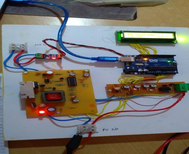
AICERA 2020                                                                                                              IOP Publishing
IOP Conf. Series: Materials Science and Engineering              1085 (2021) 012035           doi:10.1088/1757-899X/1085/1/012035

Real time supervision of faults in converter of PV system
                                      P R Jadhav1, S B Chavan*2
                                       1
                                         Student, Department of Technology, Shivaji University, Kolhapur, 416004
                                      2
                                        Department of Technology, Shivaji University, Kolhapur, India, 416004
                                      *Corresponding author’s Email ID- sbc_tech@unishivaji.ac.in

                     Abstract- PV systems are remotely installed at unmanned places. They have sub-systems like
                     converters, inverters etc. Electronic components in these circuits work under electrical stress
                     conditions. PV systems occupy huge land area; therefore system supervision and fault diagnosis
                     are critical in these applications. In this work internet connectivity based supervising system is
                     presented for boost converter to monitor its working status. The system implemented at site monitors
                     the converter output, voltage across the devices, compares it with the known standard values and
                     records it. Whenever any remote node accesses it, the formatted information is displayed which
                     shows the converter status. Due to this remote site supervision and electrical parameter observation
                     is easy.

1. Introduction
Solar PV arrays are in great demand for energy generation. Converters and inverters are important power
processing part of PV systems. Electronic devices in power processing circuits work under electrical stress
and changing atmospheric conditions. Due to this these devices are failure prone. Researchers carried
industrial surveys and signified the reliability aspects in converters of PV systems, as described in
references [1] to [7]. Few researchers developed fault tolerant converter topologies in which redundant
components were activated on arrival of fault for fault recovery [8],[9]. Various techniques are presented
for fault detection, faulty component identification and studying fault signatures and precursors [10]-[13].
A trend is also seen in this area to regularly supervise the system performance and the real time faults using
communication technologies like internet, GSM, GPRS, ZigBee etc., such systems are described in [14]-
[19]. Considering the need of remote supervision, fault prone behavior and reliability issues in remotely
located PV systems, this work focus on design of internet based supervising system for boost converter in
PV system for remote monitoring the component abnormalities. In this the voltage at device nodes are
measured to monitor the converter status remotely using smart phone or computer.

              Content from this work may be used under the terms of the Creative Commons Attribution 3.0 licence. Any further distribution
              of this work must maintain attribution to the author(s) and the title of the work, journal citation and DOI.
Published under licence by IOP Publishing Ltd                          1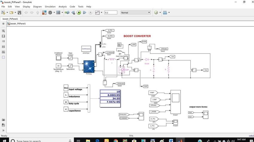
AICERA 2020                                                                                       IOP Publishing
IOP Conf. Series: Materials Science and Engineering   1085 (2021) 012035     doi:10.1088/1757-899X/1085/1/012035

2. System implementation
Boost converter is designed for PV panel; output voltage, voltage across IGBT, diode, and output capacitor
is monitored and processed. The electrical parameters across the devices under observation are monitored
and recorded after certain fixed interval. The existing parameters are also compared with the known
standard values. The information is formatted and recorded systematically. The boost converter design
specifications are given in table 1.

                                  Table 1- Boost converter design specifications

                                        Electrical Parameter         Value
                                        PV input voltage (typical)   19 V
                                        Boost converter Voutput      53 V
                                        Converter efficiency         80 %
                                        Duty cycle                   65 %

The system is designed around Arduino Uno board, TL 494 PWM controller IC is used for IGBT gate
control, ACS 712 current sensor is used for PV current sensing. Figure 1 shows system block diagram.
System simulation model is shown in figure 2. The model is used to find the voltages across devices in
normal mode and component faulty modes. Component level OC and SC faults and their fault signatures
are studied in simulation model, these fault signatures are implemented in actual system to find the faulty
component. Deviation in the voltage gain of converter indicates the occurrence of any component fault.
When such voltage gain deviation is detected, the voltage across components of the converter like IGBT,
diode, capacitor is measured. If the measured voltage across component under test is not in the desired
range, it indicates the possibility of that component fault. System flow chart is shown in figure 3.

                                         Figure 1- System block diagram

                                                         2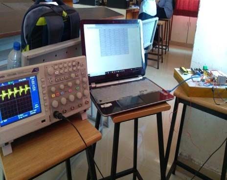
AICERA 2020                                                                                     IOP Publishing
IOP Conf. Series: Materials Science and Engineering   1085 (2021) 012035   doi:10.1088/1757-899X/1085/1/012035

                                       Figure 2- System simulation model

                                           Figure 3- System flow chart

                                                         3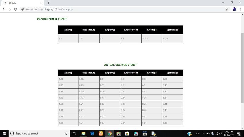
AICERA 2020                                                                                     IOP Publishing
IOP Conf. Series: Materials Science and Engineering   1085 (2021) 012035   doi:10.1088/1757-899X/1085/1/012035

Prototype developed in laboratory is shown in figure 4.

                             Figure 4- System prototype developed in laboratory

The electrical parameters of the system can be remotely monitored via computer or smart phone. The
sample screen shots of observations taken for faulty condition appear as shown in figures 5 and 6.

                             Figure 5- System parameters observed on computer

                                                         4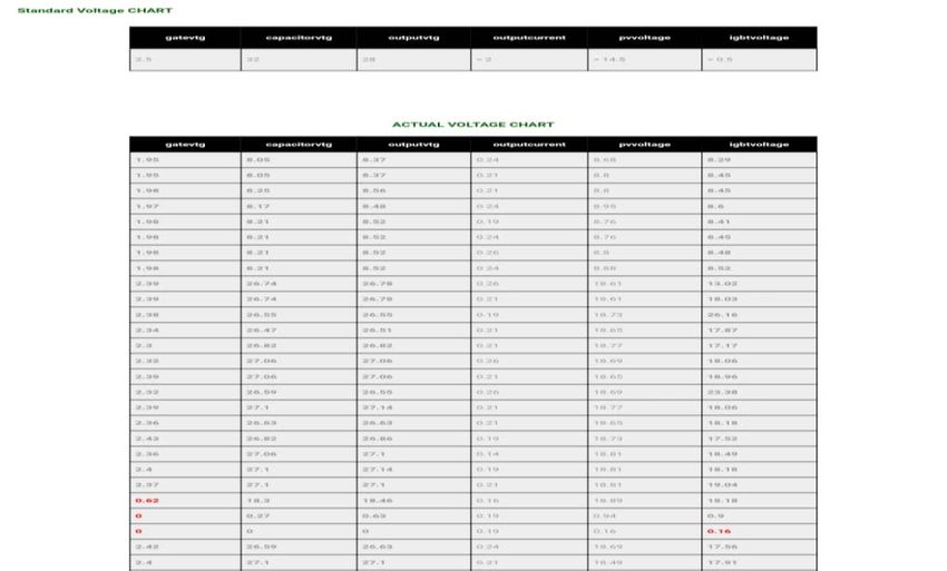
AICERA 2020                                                                                     IOP Publishing
IOP Conf. Series: Materials Science and Engineering   1085 (2021) 012035   doi:10.1088/1757-899X/1085/1/012035

                           Figure 6- System parameters observed on smart phone

The abnormalities in the electrical parameters can be highlighted with red colors as shown in sample screen
shot in figure 6. Thus remotely the system supervision can be done, prediction about any faulty component
can be done from observed parameters and possible remedial action can be planned.

3. Conclusion

The system developed in this work provides onsite real time information. For exact location of faulty
component, correct information of fault signatures is required. Typically deviation in output voltage against
input voltage provides idea about system malfunction. The voltage across device and current through it
provides exact status of component. The internet connectivity based systems facilitates remote parameter
monitoring and fault detection in PV systems. The PV systems are deployed on huge land area and they are
remotely located. Hence implementation of internet connectivity based systems for fault detection will
inform the component abnormalities at earliest; due to this quick repairing or component replacement is
possible which will avoid loss of energy generation.

4. References
[1] Petrone G Spagnuolo G Teodorescu R Veerachary M Vitelli M 2009 IEEE transactions on Industrial
Electronics 55 2569-80
[2] Wang H Ma K Blaabjerg F 2018 Proc. 38th Annual conference of the IEEE Industrial Electronics
Society 33-44
[3] Wang H Blaabjerg F Ma K Wu R 2013 4th International Conference on Power Engineering Energy
and Electrical Drives 1846-51

                                                         5
AICERA 2020 IOP Publishing
IOP Conf. Series: Materials Science and Engineering 1085 (2021) 012035 doi:10.1088/1757-899X/1085/1/012035
[4] Yang S Bryant A Mawby P Xiang D Ran L Tavner P 2011 IEEE transactions on Industry
Applications 47 1441-51
[5] Dhopale S V Davoudi A Dominguez A D Chapman P L 2012 IEEE transactions on power
electronics 27 739-51
[6] Callega H Chan F Uribe I 2007 IEEE power electronics specialists conference 1522-27
[7] Chavan S B Chavan M S 2014 International journal of advanced research in Electrical Electronics
and Instrumentation Engineering 3 11729-37
[8] Pei X Nie S Chen Y Kang Y 2012 IEEE transactions on Power Electronics 27 2550-65
[9] Pei X Nie S Kang Y 2015 IEEE transactions on power electronics 30 996-04
[10] Chavan S B Chavan M S 2014 IEEE global conference on Wireless Computing and Networking
112-15
[11] Firth S K Lomas K J Rees S J 2010 Solar Energy 84 624-35
[12] Zhao Y Lehman B Ball R Mosesian J Palma J 2013 28th IEEE applied Power electronics conference
and exposition 2913-20
[13] Houssein A Heraud N Souleiman I Pellet G 2010 IEEE International Energy Conference and
Exhibition 389-94
[14] Tejwani R Kumar G Solanki C 2014 ISES Solar world congress Energy Procedia 57 1526-35
[15] Chavan S B Kadam P A Sawant S R 2009 Instruments and experimental techniques 52 784-86
[16] Zahran M Atia Y Al-Hussain El-Sayed I 2010 12th WSEAS International Conference on automatic
control, modelling & simulation 65-70
[17] Meliones A Apostolacos S Nouvaki A 2014 Applied computing and informatics 20 14-37
[18] Chavan S B Chavan M S Information and communication technology for sustainable development
Lecture notes in Networks and Systems Springer 10 133-41
[19] Shariff F Rahim N A Ping H W 2015 Expert systems with applications 42 1730-42
Acknowledgement
The authors are thankful to Embedded systems and VLSI Design laboratory of Electronics and Tele-
communication Engineering program of Department of Technology, Shivaji University, Kolhapur for
proving necessary resources for completion of this project work.
6You can also read