Simulation of three-phase induction motor different bearing faults in Matlab Simulink environment
←
→
Page content transcription
If your browser does not render page correctly, please read the page content below

Journal of Physics: Conference Series

PAPER • OPEN ACCESS

Simulation of three-phase induction motor different bearing faults in
Matlab Simulink environment
To cite this article: S Salnikov et al 2021 J. Phys.: Conf. Ser. 1886 012009

View the article online for updates and enhancements.

                                This content was downloaded from IP address 46.4.80.155 on 08/10/2021 at 07:11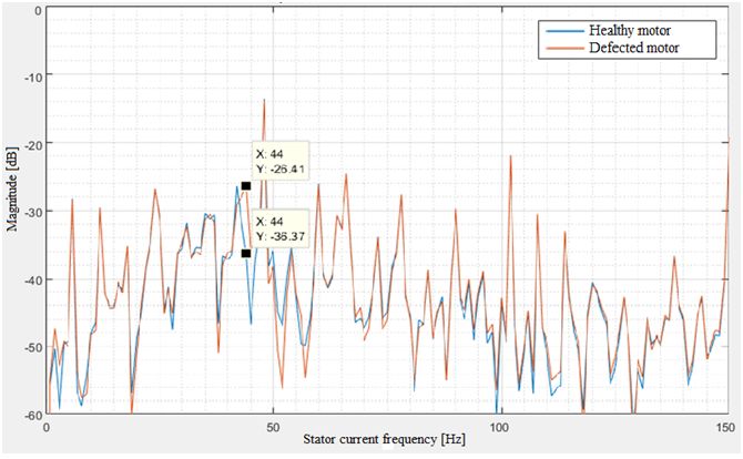
International Conference on Innovation Energy 2020 (IE 2020)                                                    IOP Publishing
Journal of Physics: Conference Series            1886 (2021) 012009                       doi:10.1088/1742-6596/1886/1/012009

Simulation of three-phase induction motor different
bearing faults in Matlab Simulink environment
                      S Salnikov1 , E Solodkiy2 and D Vishnyakov3
                      1
                        Engineer, Electrical Engineering Faculty, Perm National Research Polytechnic University,
                      Perm, Russia
                      2
                        Assistant professor, Electrical Engineering Faculty, Perm National Research Polytechnic
                      University, Department of Microprocessor Automation, Perm, Russia
                      3
                        Student, Electrical Engineering Faculty, Perm National Research Polytechnic University,
                      Perm, Russia
                      E-mail: zav@msa.pstu.ac.ru
                      E-mail: solodky em@pstu.ru
                      E-mail: zav@msa.pstu.ac.ru

                      Abstract. The article describes the simulation of bearing failures in a three-phase induction
                      motor in the Matlab Simulink environment. According to statistics most of induction motor
                      faults happens due to bearings destruction or stator winding insulation degradation. Vibration
                      analysis is often used to diagnose the bearings condition. This paper considered the model
                      designing principles of different types of bearing faults of induction motor.

1. Introduction
Today, the induction motor (IM) is the most common type of electric machine. This type can be
found in all types of industries. Examples are used the oil industry, heat-generating companies,
electric power industry, etc. In industrial practice, there are known cases an IM failure due to
electrical and mechanical types of breakdowns. Mechanical failures are of the greatest interest.
This type of fault is common in manufacturing plants due to difficult operating conditions
and improper motor service. In scientific and engineering practice, IM diagnostic algorithms
are tested on test-benches using real faulty equipment, which is not always available for use.
Testing on mathematical models can be a preliminary step in diagnostic algorithms debugging
[1-3]. This type of debugging allows to make additional adjustments of microcontroller program
before field experiments. Therefore, the development of IM failure models is one of the most
important tasks in the overall algorithms development for motor diagnostics.

2. Studying of the problem
In practice, the dynamic fault models are commonly used for testing diagnostic algorithms. For
this reason, a system of dynamic equations describing electromagnetic and electromechanical
processes in the motor is used to build an IM model (1) [1, 2].

              Content from this work may be used under the terms of the Creative Commons Attribution 3.0 licence. Any further distribution
              of this work must maintain attribution to the author(s) and the title of the work, journal citation and DOI.
Published under licence by IOP Publishing Ltd                          1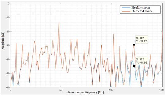
International Conference on Innovation Energy 2020 (IE 2020) IOP Publishing
Journal of Physics: Conference Series 1886 (2021) 012009 doi:10.1088/1742-6596/1886/1/012009
di 1
sα
= (Usα − Re isα + Kr Zp ωr ψrβ + Kr Ar ψrα );
dt Le
disβ 1
= (Usβ − Re isβ + Kr Zp ωr ψrα + Kr Ar ψrβ );
dt Le
ψrα
= Rr Ar isα − Ar ψrα − Zp ωr ψrβ ;
dt
ψ
rβ
= Rr Ar isβ − Ar ψrβ − Zp ωr ψrα ;
dt (1)
3
Me = Zp Kr (ψrα isβ − ψrβ isα );
2
dωr 1
= (Me − M c);
dt J
e
ψrβ
θ = arctan ;
ψrα
where ψrβ , ψrα - rotor flux in α β coordinates [Wb]; ψsβ , ψsα - stator flux in α β coordinates
[Wb]; irβ , irα - rotor current in α β coordinates [A]; isβ , isα - stator current in α β coordinates
[A]; Usβ , Usα - IM stator voltage in α β coordinates [V]; Rr and Rs - rotor and stator resistance
[Ohm]; Me - electromagnetic torque [Nm]; Mc - load torque [Nm]; θ - rotor flux position angle
[rad]; Zp - pole pairs; Ls - stator inductance [H]; Lr - rotor inductance [H]; Lm - magnetization
Lm L2 Lm
inductance [H]; Kr = , Re = Rs +Kr 2 ,Le = Ls − m , Ar = - accepted designations.
Le Lr Le
The Matlab Simulink SimPowerSystems library has an IM with squirrel-cage rotor model.
The model is used in this paper. The IGBT model of an inverter with a scalar control system
is used as a source for the motor (fig. 1).
Figure 1. IGBT inverter model with scalar control system as source for induction motor
Vibration on the IM shaft occurs due to various bearing defects such as inner and outer
2International Conference on Innovation Energy 2020 (IE 2020) IOP Publishing
Journal of Physics: Conference Series 1886 (2021) 012009 doi:10.1088/1742-6596/1886/1/012009
raceway ring fault or bearing balls destruction [3, 4]. The bearing vibration characteristic
frequency corresponds to each of the fault types:
Dc2 Db2
f b = 2 f r (1 + 2
cos2 β);
D D
c
b
Nb Db
fi = fr (1 + cos β);
2 Dc (2)
Nb Db
fo = fr (1 − cos β);
2 Dc
where fo – vibration characteristic frequency of bearing with outer raceway ring fault [Hz], fi –
vibration characteristic frequency of bearing with inner raceway ring fault [Hz], fb – vibration
characteristic frequency of bearing with ball destruction fault [Hz], Nb – number of bearing
balls; Dc – bearing separator diameter [mm], Db – ball diameter [mm], Di – inner raceway ring
diameter [mm], Do – outer raceway ring diameter [mm], β – ball contact angle, fr – rotor speed
[Hz].
Vibration on the motor shaft can be simulated using an additional pulsing load torque, which
equals to:
Mbf = Mc (1 + cos 2πfc t) (3)
where Mbf – additional load torque, which is the equivalent of vibration for various bearing
faults, Mc – torque magnitude, fc – vibration characteristic frequency of bearing fault, t – time
[s].
The torque amplitude depends on the degree of bearing destruction. Also, the pulsation value
depends linearly on the load torque. Additional load torque computing in Matlab Simulink
depicted in figure 3.
Figure 2. Additional load torque computing in Matlab Simulink environment
It is assumed that the motor is operated with a rated load of 14 [Nm], so a healthy motor is
loaded with a high torque value. If there are bearing faults, the load torque is added to the load
3International Conference on Innovation Energy 2020 (IE 2020) IOP Publishing
Journal of Physics: Conference Series 1886 (2021) 012009 doi:10.1088/1742-6596/1886/1/012009
torque calculated using the equation 2. For each type of fault, the frequency of the additional
torque caused by a specific bearing fault is different. Calculation of the load torque in a unit of a
faulty bearing is performed in the block (Load ). The input unit receives the bearing parameters
(Nb, Dc, Db), the relative frequency amplitude plus the amplitude of the faulty bearing (Amp)
rated load torque (Torque) and he rotor speed of the IM (Speed ). The output parameter is the
torque of load: in case of the faulty outer bearing race (Outer ); defective inner race (Inner );
bearing fault ball (Ball ).
It is known that vibration on the shaft of an asynchronous motor causes the growth of
harmonics at the frequencies at which it occurs. This feature is the basis of the method for
diagnosing the state of an IM using spectral analysis of the stator current. Therefore, we can
check the adequacy of the model by modeling this diagnostic method at Matlab. The magnitude
of the stator current vector (or Park vector) is calculated for further spectral analysis. The
complex model includes electric drive systems with a healthy motor and motors with various
bearing defects (fig. 3). The stator current Park vector magnitude is calculated and recorded
during the simulation in each model subsystem.
Figure 3. Complex model in Matlab Simulink environmentt
3. Simulation results
The rotor speed at rated load was 137 rad/s. Calculated frequencies that simulate faults
associated with the bearing faults equals (2): fi = 121.37 [Hz]; fo = 74.96 [Hz]; fb = 43.54
[Hz]. Spectral analysis of the Park vector was performed using the Matlab script (fig.4, 5, 6).
The using motor parameters, which are presented in table 1.The parameters of the simulated
bearing are shown in table 2.
As a result of spectral analysis of the stator current vector magnitude in the presence of a
defect in the outer ring bearing, an increase of 23.1 dB in the harmonic component of 75 Hz was
detected, which in turn coincides with the frequency of vibration on the rotor shaft. Therefore,
this component, when diagnosing the motor, clearly indicates the presence of a fault associated
with the outer ring bearing.
4International Conference on Innovation Energy 2020 (IE 2020) IOP Publishing
Journal of Physics: Conference Series 1886 (2021) 012009 doi:10.1088/1742-6596/1886/1/012009
Table 1. Parameters of IM.
Notation Parameter Values
P Rated power 2.2 [kW]
n Rated speed 1470 [rpm]
Rr Rotor resistance 3.297 [Ohm]
Rs Stator resistance 3.6012 [Ohm]
Ls Stator inductance 0.1769 [H]
Lr Rotor inductance 0.1769 [H]
LM Mutual inductance 0.168 [H]
J Rotor inertia 0.035 [kg · m2 ]
Zp Number of pole pairs 2
Figure 4. Spectrogram of current vector for motor with outer raceway ring bearing defect
Table 2. Parameters of IM.
Notation Parameter Values
Do Outer ring diameter [mm] 52
Dt Inner ring diameter [mm] 25
Dc Bearing separator diameter 33.5
Db Ball diameter [mm] 7.94
Nb Number of bearing balls 9
β Ball contact angle [rad] 0
Similarly, the harmonic component of 122 Hz increased by 15.3 dB (fig. 5). The growth of
5International Conference on Innovation Energy 2020 (IE 2020) IOP Publishing
Journal of Physics: Conference Series 1886 (2021) 012009 doi:10.1088/1742-6596/1886/1/012009
Figure 5. Spectrogram of current vector for motor with inner raceway ring bearing defect
this harmonic is caused by an inner raceway defect of bearing. A 10 dB increase in the harmonic
component of 44 Hz was also detected when modeling a motor with defective bearing balls (fig.
6).
Figure 6. Spectrogram of current vector for motor with ball bearing defect
4. Summary
As a result, all simulated bearing failures were detected on the current vector spectrogram at the
corresponding frequencies. This means that the simulated faults adequately reflect real events.
In the future, a full-scale model will be designed on the basis of laboratory-bench, which will
include an IM with the possibility of replacing bearings with faulty ones. It is possible that
6International Conference on Innovation Energy 2020 (IE 2020) IOP Publishing
Journal of Physics: Conference Series 1886 (2021) 012009 doi:10.1088/1742-6596/1886/1/012009
the developed model in Matlab Simulink will be corrective with experimental results.Proposed
model allows to test IM diagnostics algorithms in Matlab Simulink environment. The model
can also be used as a part of semi-natural fault simulation laboratory bench that includes the
test IM and direct current motor on the same shaft producing vibration torque corresponding
to bearing fault.
It is assumed that the results of the work will be included in the training course of the
new master’s program “Conceptual Design and Engineering of Improving Energy Efficiency” for
the training of engineering skills, scientific personnel and management personnel in the power
industry, grid companies and related sectors [5].
Acknowledgments
Research is also supported by educational and research grant 573879-EPP-1-2016-1-FR-
EPPKA2-CBHE-JP by European program Erasmus+ (Project INSPIRE).
References
[1] Anuchin A 2015 M.: Publishing House of the MEI
[2] Sokolovskiy G G 2006 AC electrical drives with variable-frequency drive (Academia)
[3] Bayram D and Şeker S 2015 Soft Computing 19 1107–1114
[4] Frosini L and Bassi E 2009 IEEE Transactions on Industrial electronics 57 244–251
[5] Lyakhomskii A, Perfilieva E, Petrochenkov A and Bochkarev S 2015 Conceptual design and engineering
strategies to increase energy efficiency at enterprises: Research, technologies and personnel 2015 IV Forum
Strategic Partnership of Universities and Enterprises of Hi-Tech Branches (Science. Education. Innovations)
(IEEE) pp 44–47
7You can also read