Excitation Systems 10 kVA - 25 MVA alternators - Leroy Somer

Page created by Cynthia Flores
 
CONTINUE READING
Excitation Systems 10 kVA - 25 MVA alternators - Leroy Somer
Excitation Systems

10 kVA - 25 MVA alternators
Excitation Systems 10 kVA - 25 MVA alternators - Leroy Somer
REGULATORS AND EXCITATION SYSTEMS ARE AT THE HEART OF INDUSTRIAL ALTERNATORS
            PERFORMANCE AND RELIABILITY.

            At Leroy-Somer, we design, test and qualify our electronic products to meet the challenges of power
            generation systems. Using our experience and field expertise, we provide regulation features that help
            protect installations from outage and failures, and our excitation systems are optimized to provide the
            best performance levels for any situation.

                                                   EXCITATION SYSTEMS

            Leroy-Somer offers different excitation systems to match application requirements. An excitation system uses the
            alternator output to build an excitation current that is then used to power the rotating magnetic field of the rotor.
            This principle allows for the control of the output power.

            To build excitation current, a regulator needs both a supply voltage to provide power, and a measured reference
            voltage at output terminals to pilot the excitation.

                                                                                        Alternator
                                                                                            Alternator
Main power
   Main power
 output                                       User input                   N                                                                      Exciter
      output                                     User input                     N                                                                    Exciter
                                                                               U
            Sensing +                                                               U
            AVRSensing +
                power supply                                                   V
               AVR power supply     AVR                                             V
                                      AVR                                      W
                                                                                    W
                                                  AVR
                                                     AVR
                                                  output                                                                                           +        -
                                                     output                                                                                             +       -

                                                                                                                                   Exciter current
                     STATOR                                                                                                           Exciter current
                        STATOR       Diode          Exciter
                                         Diode          Exciter
                                                    stator
                                     bridge             stator
                                         bridge
Prime                                                                    Power
   Prime                                            Exciter                 Power
                                                                         supply
system                ROTOR                         rotorExciter            supply
   system               ROTOR                           rotor
                                                                         Voltage                                -
                                                                            Voltage
                                                                         sensing                                   -              Control
                                                                            sensing                             Comp.    PID         Control
                                            Exciter                                                                Comp.     PID command
                                               Exciter                                              Ref         +                   command
                   Main power                                       External                              Ref       +
                     Main power                                        External
                                                                   reference
                                                                      reference

                                                   Diagram of a complete excitation system
Excitation Systems 10 kVA - 25 MVA alternators - Leroy Somer
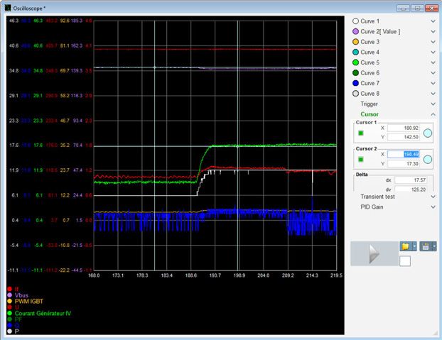
SHUNT                                                                     The SHUNT excitation system can also be completed
                                                                          by a booster system for larger installations to allow
In SHUNT excitation systems, the AVR power supply
                                                                          for short circuit capability. In this situation, current
and voltage reference are picked on the same output
                                                                          transformers are added in the terminal box to
terminals. The AVR generates and regulates the
                                                                          increase supply voltage range. This solution is not
excitation current as a function of the alternator
                                                                          always possible and adds an extra cost due to the
output voltage.
                                                                          transformers purchase & installation.
The SHUNT system is extremely simple in its design
and is ideal for standard applications. AREP or PMG
systems are more relevant for demanding situations
                                                                                                                         Field winding
where short circuit currents are anticipated
                                                                                  Stator winding            Diodes
(for example for motor start-up).

                                               Rotor
                                               winding                                                                  Armature

                                                                                                               A.V.R.

 COMPACT          ECONOMIC

                                                         Alternative current
                                                         Direct current
                                                         Voltage sensing

AREP+                                                                     The AREP+ system improves the electrical performance
                                                                          of equipped machines, especially during transient short
The new AREP+ system by Leroy-Somer uses the
                                                                          circuit, load shedding or load impact phases.
output voltage of the main stator as supply voltage
                                                                          As a result, the starting kVA performances are
and a single auxiliary winding inserted in selected slots
                                                                          improved by up to 30% depending on generator
of the main stator for booster effect. The combination
                                                                          model (vs a standard AREP system). This level of
of these two sources is then used to power the
                                                                          performance is decisive when generators are used
regulator, thus combining the power of a traditional
                                                                          to start electric motors. The AREP+ system gives
SHUNT system with the reliability and control level
                                                                          the alternator a high short circuit capability (for LSA
of an AREP system. Under the same conditions, more
                                                                          range: 300% - 10 s).
power is taken to supply the regulator, which improves
the excitation capabilities.
                                                                                                                          Field winding

                                                                                  Stator winding            Diodes

                                               Rotor
                                               winding                                                                  Armature

 COMPACT        SHORT CIRCUIT

                                                                                                               A.V.R.

                                                         Alternative current
TRANSIENT                                                Direct current
                                                         Auxiliary winding
                                                         Voltage sensing
                                                         X1X2 connection (Ph-N)
Excitation Systems 10 kVA - 25 MVA alternators - Leroy Somer
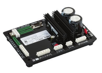
AREP                                                                              The power supply to the AVR power circuit is
                                                                                  independent from the voltage sensing measured on
In AREP excitation systems, the AVR power supply
                                                                                  the alternator output terminals.
comes from two separate auxiliary windings. The
                                                                                  Therefore, the excitation current delivered by the
voltage delivered by the first auxiliary winding H1 is
                                                                                  AVR to the alternator exciter is not affected by any
proportional to the alternator output voltage (SHUNT
                                                                                  voltage distortions (harmonics) due to the load. The
characteristic).
                                                                                  AREP system gives the alternator a high short circuit
The voltage delivered by the second auxiliary winding
                                                                                  capability (for LSA range: 300% - 10 s).
H3 is proportional to the current drawn by the alternator
and is a function of the applied load ( booster effect).
                                                                                                                                     Field winding

                                                                                           Stator winding               Diodes

                                                     Rotor
                                                     winding                                                                        Armature

 COMPACT           SHORT CIRCUIT

                                                                                                                           A.V.R.

                                                                 Alternative current
TRANSIENT                                                        Direct current
                                                                 Auxiliary winding
                                                                 Voltage sensing

PMG                                                                               and secure the system startup, even after long
                                                                                  shut-down periods. Because it is external to the
In PMG excitation systems, the AVR power supply
                                                                                  alternator system, a PMG can be installed on an
voltage is generated by a permanent magnet
                                                                                  existing machine (SHUNT or AREP) when required.
generator (PMG) that is mounted on the shaft
extension at the non-drive end of the alternator. The                             As an alternative to PMG, the SHUNT, AREP or AREP+
PMG delivers a constant voltage, regardless of the                                systems can be completed with permanent magnets
main alternator winding. PMG systems have high                                    inserts (PMI). In this case, permanent magnets are
overload and short circuit (for LSA range: 300% - 10 s)                           mounted on the exciter stator poles.
capacities.   The     permanent    magnets           used           in
the PMG ensure enough remanent magnetism
                                                                                                                                               P.M.G.
                                                                                                                          Field winding

                                                                                 Stator winding             Diodes

                                        Rotor
                                        winding                                                                         Armature

RETROFIT           SHORT CIRCUIT

                                                                                                               A.V.R.

TRANSIENT                                         Alternative current
                                                  Direct current
                                                  Voltage sensing
Excitation Systems 10 kVA - 25 MVA alternators - Leroy Somer
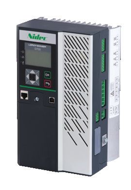
EXCITATION SYSTEMS COMPARISON
                                                   SHUNT                    AREP+            AREP                   PMG
Transient performances

Short circuit performances

Non-linear loads                                                              *                *                     *
Voltage build-up                                   Residual             Residual            Residual         Perm. Magnets
Footprint                                            Small                  Small            Small                Important
Conversion                                         To PMG                   To PMG          To PMG          To SHUNT / AREP
Cost                                                     $                   $$                $$                    $$

EXCITATION SYSTEMS SHORT CIRCUIT PERFORMANCES COMPARISON

The graph below illustrates the compared performance of SHUNT, AREP, AREP+ and PMG excitation systems in
short circuit current situations.

                Voltage (V)
                                                                                                                   AREP / PMG
              Rated voltage
                                                                                                                   AREP+
                                                                                                                   SHUNT
                  Sustained
                voltage drop

                                                                                                       Load (%)
                                        100 %                       200 %              300 %

                                                Example for LSA range

                                     AVR RANGE & FEATURES

AVR MODEL                              D350      D550         D700          R120     R150      R180        R220          R250
Technology                                       Digital                                       Analog
SHUNT
AREP / AREP+
PMG
Rated excitation current (A, 55°C)      5          8           20            4        6            6        3.2            5
Regulation accuracy (+/- %)            0.25       0.25        0.25           1       0.8        0.5         0.5           0.5
Voltage setting range (+/-%)            30         30          30            10       10           5         5             5
Paralleling between gensets (droop)
Three-phase sensing
LAM
Over-excitation limitation
Short circuit current limitation
Grid paralleling (PF / kVAr)
Excitation Systems 10 kVA - 25 MVA alternators - Leroy Somer
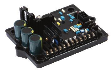
LEROY-SOMER PRODUCTS

      LSA RANGE
                               LSA 40     LSA 42.3     LSA 44.3     LSA 46.3    LSA 47.2    LSA 49.3     LSA 50.2
               SHUNT                  R220                            R250                       -           -
          AREP+ / PMG                                                 D350

                               LSA 52.3 LSA 53.2       LSA 54.2      LSA 56      LSA 58      LSA 60       LSA 62
            SHUNT
                                             D550                                         D700
          AREP+ / PMG

      TAL RANGE
                               TAL 040    TAL 042      TAL 044      TAL 046     TAL 0473     TAL 049
               SHUNT                         R120                                 R150
          AREP+ / PMG                                          R180

   R120                 R150                   R180                   D350                   D550                  D700

The regulator model can change according to specific options (UL, remote potentiometer, 1-phase) or specific requirements.
Please consult our catalogs & rating tables for details.

                                    REGULATION FEATURES

PID                                                            alternator voltage is reduced. This prevents saturation
PID is the regulation system function which combines           in the excitation system and protects the alternator
different rules (Proportional, Integral, Derivative)           rotor from any damage.
to stabilize the current produced by the alternator.
Tuning this function allows to optimize the response           LAM function
time of the system to reach the voltage set point, or          The LAM (Load Acceptance Module) is a function that
to stabilize it quickly in case of fluctuations. It is an      adapts the alternator voltage according to the rotation
essential component of any regulation system.                  speed of the prime mover. It is triggered in the event
                                                               of a load impact. The LAM considerably reduces the
U/f function                                                   alternator voltage which results in decreased power
U/f is a function designed to handle underspeed                demand on the prime mover.
situations. It allows to adapt the alternator voltage          As the speed climbs back to normal, the alternator
according to the rotation speed of the prime mover. If         voltage re-established.
the system speed is lower than the nominal speed, the
Excitation Systems 10 kVA - 25 MVA alternators - Leroy Somer
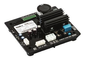
Three-phase sensing                                          The active reverse power occurs on the machines
The regulator needs voltage measurement in order to          paralleled with other machines or a network. The
maintain the voltage on the alternator output terminals.     active power on the alternator’s output terminals must
Three phases sensing means that voltage detection and        always be positive. A negative power means that the
measurement is done on all three phases of the alternator,   alternator starts to act as an electric motor, which can
which allows to regulate the average voltage. This means     fatally damage the prime mover. The active reverse
that regulation is more precise and safer.                   power allows to disconnect the alternator from the
                                                             network to avoid the failure.
Short circuit current limitation
                                                             An absorption of reactive power deenergizes the
The short circuit current limitation is triggered during
                                                             alternator and thus reduces the magnetic flux between
short circuits. It is adjusted on the regulator and
                                                             the rotor and the stator. Too much absorption may
allows to limit the delivered current during 10 seconds
                                                             cause pole slipping, which can severely damage not
maximum. This prevents the alternator from getting
                                                             only the alternator, but also the mechanical coupling
damaged by a too strong current.
                                                             with the drive system. The reverse reactive power alert
                                                             will also disconnect the alternator from the network in
Active & Reactive reverse power alarm
                                                             this situation.
These functions are only possible if you use a D550
or a D700 regulator. A wired current transformer is
necessary to calculate the active and reactive powers.
In this case, the regulator will be able to control it.

                                        EASYREG ADVANCED

EasyReg Advanced is the dedicated software to configure and monitor Leroy-Somer digital Automatic Voltage
Regulators (AVR). It is compatible with the D350, D550 and D700.

EasyReg Advanced includes a
complete set of tools:
• Step-by-step configuration of
   the alternator parameters,
   regulation modes, limits, wiring,
   PID, I/O and protection devices
• Monitoring and analysis tools,
   including an oscilloscope, a
   monitoring panel, and harmonic
   analysis
• Grid code protection parameters
   definition and synchronization
   parameters for grid paralleling
Excitation Systems 10 kVA - 25 MVA alternators - Leroy Somer
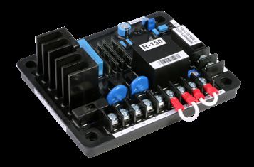
www.leroy-somer.com/epg

Linkedin.com/company/leroy-somer
Twitter.com/Leroy_Somer_en
Facebook.com/LeroySomer.Nidec.en
YouTube.com/LeroySomerOfficiel

                                           © Nidec 2020. The information contained in this brochure is for guidance only and does not form part of
                                           any contract. The accuracy cannot be guaranteed as Nidec have an ongoing process of development
                                           and reserve the right to change the specification of their products without notice.

                                           Moteurs Leroy-Somer SAS. Siège : Bd Marcellin Leroy, CS 10015, 16915 Angoulême Cedex 9, France.
                                           Capital social : 38 679 664 €, RCS Angoulême 338 567 258.

                                                                                                                             4124 en - 2020.04 / f
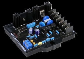
Excitation Systems 10 kVA - 25 MVA alternators - Leroy Somer
You can also read