Transmitting Live Aircraft Security Data by 3G
←
→
Page content transcription
If your browser does not render page correctly, please read the page content below
Transmitting Live Aircraft Security Data by 3G
Steve Lane, Commercial Director at electronic design consultancy Triteq, talks about how commercial
3G mobile phone technology has been adapted to monitor security through live data links onboard
planes.

Unlocking the Potential of 3G
Air traffic across Europe is at an all time high and consequently, the aviation industry is
running short of radio spectrum for communications. Additionally, onboard security has
presented a new challenge to airlines. To help find a solution to this, the European
Commission and Eurocontrol, the organisation in charge of air navigation in Europe, has
explored the potential of 3G wideband technology as an alternative medium for
communications intended for security. Having had successful results with previous trials of
3G communications in various aeronautical spectrum bands, Eurocontrol has recently been
looking at 3G as a potential solution for Air Traffic Management (ATM) security.

Developing an Air Traffic Management (ATM) Security System
One option in developing an ATM security system was to provide a high capacity air-ground
downlink that would support the transmission of encrypted voice, flight data and onboard
video. This could be transmitted from the cockpit of an aircraft during a security alert. Such
information would provide ground based decision makers with a clearer picture of the
situation onboard the plane.
The EU TEN-T (Trans European Network-Transport) funded project, known as European
Aviation Security based on 3G technology (EAS-3G), is based on a C-band air-ground link
operating at a frequency of around 5GHz. The International Telecommunications Union has
allocated aeronautical spectrum for this purpose. The project aims to adapt existing 3G
technology to avoid the high costs of developing an entirely new system.

EAS-3G System Overview
The concept of the project’s system is that ‘traditional’ node B and UE elements of the UMTS
TDD system are replaced by ground stations (reconfigured node Bs) and air stations
(reconfigured 3G PCMCIA modem). A data link is established and maintained between an
air station and a ground station, and the system is capable of performing handovers across
the cell boundaries between the ground stations. In effect, the 3G UMTS TDD technology
provides an IP bit-pipe between the ground segment and the air station.
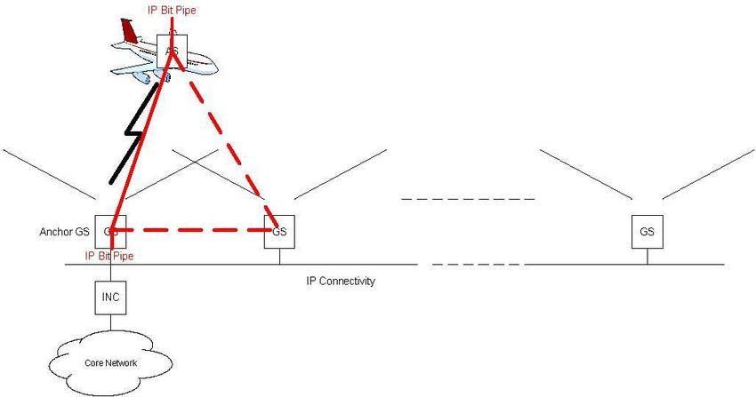
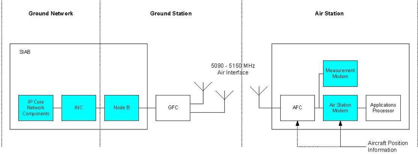
Figure 1 shows the basic EAS-3G system concept with Ground Stations (GS), Air Stations
(AS) and Integrated Network Controllers (INCs).

Figure 2 shows a top-level functional breakdown of the system into the ground station, air
station and ground network sub-systems. The air interface operates in the 5090 – 5150 MHz
frequency band, thus requiring frequency converters at both ends; the Ground Frequency
Converter (GFC) and the Air Frequency Converter (AFC). The TDD equipment (indicated in
blue) consists of node Bs, Integrated Network Controllers (INCs) and PCMCIA Modems,
plus elements of the core network.

Figure 2

System Components and Technical Challenges
Triteq became involved in the project in 2006, after initial equipment concept trials had been
carried out by Eurocontrol. There was a requirement to develop a working test system based
on a commercially available 3G modem, enclose this in an avionics box and conduct flight
trials. Triteq provided electronics design support to the project, which meant overcoming
several technical challenges in selecting the right components. A key aspect of the project
was to adapt a commercially available modem and ensure the system would operate at
aircraft speeds.
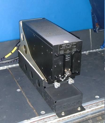
An industry standard ARINC 4MCU enclosure, as illustrated above, was used. The complete
design had to be certified for air-worthiness to allow flight trials to be conducted, so this was
an important consideration in the selection of both the enclosure and other system
components.

Ground Station
The ground station was based on industry standard UMTS-TDD equipment working
at 1.9 GHz with a subsequent frequency conversion to the 5GHz aeronautical band.
The converter was a separate development carried out by Triteq in parallel with the
avionics circuit board manufacture.
However, one of the main technical challenges in the project was implementing the avionics
equipment particularly because of size, power and weight constraints. This part of the
system is further described below.

Air Side Configuration
The basic configuration of the avionics system was conceived as a PCMIA 3G modem with
the receive and transmission signals being converted between 2GHz and 5GHz for the air
interface link. A PC104 module was used to provide control functions including the
compensation for Doppler shift and the correct timing advance for the RACH (Random
Access Channel) transmissions.

Modifications to Avionics Modem
A commercially available 3G modem was selected to minimise development costs for the
project. This modem had to be modified to gain access to specific signals and to split the
transmit and receive signals from the modem. In addition, the extended timing advance
mechanism within the modem had to be controlled. The range limitation (due to the RACH
configuration) was solved by sacrificing a timeslot and by modifying the RACH burst type
and mapping it to a normal burst. These changes to the modem, and to Node-B in the
ground station were implemented with collaboration from the UMTS equipment supplier.

The 1.9 GHz transmit signal from the modem is up-converted to 5 GHz before transmission
from the antenna and the 5 GHz signal from the antenna is down converted to 1.9 GHz to
the modem.

Overcoming Doppler Shift
UMTS is not designed to cater for aircraft velocity; 250 km/hr is about the maximum velocity
possible, but planes can cruise at ground speeds in excess of 1000 km/hr. As a result, there
is a Doppler shift which is well outside of the normal operating tolerance of the 3G system.
Triteq had to enable the modem to compensate for both Doppler shift and reference
frequency tolerance using an Automatic Frequency Control (AFC) methodology. AFC was
determined from the decoded received signal and used to control the reference crystal
oscillator, which in turn was used to provide the clock for digital processing and to phase
lock the local oscillator for both the received and transmitted signals. It corrected the
frequency error of the reference oscillator. The 3G Modem originally used an analogue AFC
applied to a 15.36 MHz voltage controlled crystal oscillator (VCXO).

To obtain maximum performance it was necessary for the mobile modem to appear near
stationary with respect to the fixed ground station. Hence the Doppler shift compensation
applied to the transmitted signal had to be equal and opposite to that of the received signal.
So the transmit (Ftx) and receive (Frx) frequencies for a nominal channel frequency
(Fchannel) were corrected by the Doppler frequency (Fdoppler).
Frx = Fchannel + Fdoppler
Ftx =
The Doppler frequency was estimated based on the position and velocity of the aircraft
relative to the base station – the information being provided from the Aircraft Navigation
Systems through an ARINC interface to the module.

Doppler Correction
The frequency error introduced by Doppler shift depends on the speed of travel and the
frequency of operation. For a worst-case scenario the highest operating frequency of 5150
MHz and a speed of 1225 km/h (Mach 1 at sea level) was assumed. This produced a
Doppler shift of +/- 5.8 KHz. The frequency synthesiser therefore had to allow for this range
of Doppler correction.

Frequency Drift
The initial frequency error between the modem and the base station needed to be corrected.
The AFC mechanism in the modem was designed to correct for the frequency error
introduced by a crystal oscillator in the modem. A higher specification part had to be
substituted in place of the modem oscillator. This improvement had to be sufficient to allow
for the error introduced by the frequency translation.

Phase Noise and Spurs
The system does not have to fully meet the 3GPP standards because it is not connected
directly to a commercial network. It is also subject to different types of interference, both co-
channel and adjacent channel, so it is not possible to fully specify the phase noise and spur
requirements.
Good RF filtering was provided so out of band spurs did not need to be suppressed. An
initial target of non harmonic spurs of
Test and Future
The prototype system has been successfully tested by Eurocontrol, both on the ground and
in the air with ground to air communication achieving high-speed live data and video
transmission.

Using Triteq’s technical expertise, the project demonstrated that working with commercially
available products can significantly reduce system development costs. Since the completion
of the prototype design Triteq has been working further with Eurocontrol on the evolution of
system design, including improved spectrum utilisation and frequency synthesis/control. This
next stage supports Eurocontrol’s move towards a working Air Traffic Management security
system.
Steve Lane is Commercial Director at Triteq (email: steve.lane@triteq.com, Tel: +44 (0)1488 684554,
www.triteq.com).
You can also read