Steamer Line Hollow Fiber Cartridges - Installation and Operating Instructions
←
→
Page content transcription
If your browser does not render page correctly, please read the page content below
C: 100           C: 100
         M: 25            M: 0
         Y: 15            Y: 0
         K: 0             K: 0

Installation and
Operating
Instructions

Steamer Line
Hollow Fiber
Cartridges

www.watersep.net

   Designed for perfusion and aseptic applications, WaterSep’s Steamer Line autoclavable
   hollow fiber cartridges are gamma irradiated and ready to use. They do not contain
   humectant and are pre-wetted with deionized water so minimal flushing is needed
   before use. The cartridges can be cleaned, stored and autoclaved up to five (5) times.

   Contents:
   1. Connect the Steamer cartridge into a crossflow system.
   2. Autoclave the Steamer cartridge or system, if required for your application.
   3. Measure the water flux and normalized water permeability if intended to reuse.
   4. Integrity test the Steamer cartridge.
   5. Condition the Steamer cartridge with buffer before introducing product.
   6. Run the filtration process and recover your product.
   7. Clean the Steamer cartridge if intended to reuse.
   8. Store the Steamer cartridge.
   9. Flush the Steamer cartridge to remove the storage solution.
Installation & Operating
Figure 1: Crossflow System
C: 100 C: 100
M: 25 M: 0
Y: 15 Y: 0
K: 0 K: 0
PR
RETENTATE
PP
PERMEATE
WaterSep
RESERVOIR
CARTRIDGE
PF
FEED
1. Connect the Steamer cartridge into a perfusion/crossflow system
Inspect the cartridge
On the bag containing the cartridge, check that the gamma label is red indicating that the cartridge was gamma
irradiated. Open the bag and remove the caps and plugs from all the ports on the cartridge.
Connect the cartridge
Connect the cartridge to the crossflow system. Figure 1 shows a typical crossflow system with tubing, pump, valves
and pressure sensors. The retentate and permeate should be connected to appropriate containers or a bioreactor.
Table 1: Operating Limits
Maximum
Maximum Maximum Operating
Transmembrane
Feed Pressure Temperature pH Range
Pressure (TMP)
bar psi bar psi °C °F
0.45µm & 0.2µm 1.0 15 0.7 10 40 104 2 to 13.5
0.1µm 1.4 20 1.0 15 40 104 2 to 13.5
750K MWCO 1.7 25 1.4 20 50 122 2 to 13.5
500K - 300K MWCO 2.1 30 1.7 25 50 122 2 to 13.5
100K - 3K MWCO 2.8 40 2.4 35 60 140 2 to 13.5Instructions Steamer Line Hollow Fiber Cartridges
Re-Wet the cartridge (Optional)
New WaterSep Steamer Line hollow fiber cartridges are pre-wetted with deionized water or can be re-wetted with
deionized water prior to autoclaving. The recommended re-wetting volume for new cartridges is 0.5L/m2 through the
permeate for 5 minutes. For rinsing storage solution from a used cartridge, refer to Step 9.
To re-wet the cartridge and system, fill the reservoir with water. Start the feed pump at a slow speed. Use a pinch
valve on the retentate to generate backpressure and transmembrane pressure (TMP) to get permeate flow through
the fibers. Slowly increase the pump speed so the TMP = 0.5 — 10 psig to wet the cartridge and remove air from the
system. TMP is calculated using the equation:
TMP = {(P feed + P retentate) / 2} − P permeate
Direct the retentate and permeate to waste. During flushing, adjust the retentate backpressure. After the cartridge and
system is re-wetted, decrease the feed pump speed then stop the feed pump and discard the waste.
2. Autoclave the Steamer cartridge or system, if required for your application
The cartridge can be autoclaved connected to a system. Plastic sanitary clamps should be loose for autoclaving.
The cartridge should be autoclaved using a liquid or wet cycle for 35 minutes at 121°C (maximum); do not use a dry
or solid autoclave cycle. Once the autoclave cycle is complete, allow the cartridge to cool to ≤50°C degrees prior
to handling. The sanitary clamps can be re-tightened after the cartridge has cooled to ≤50°C degrees. WaterSep
Steamer Line cartridges can be autoclaved up to five (5) times.
3. Measure water flux and normalized water permeability if intended to reuse
If the cartridge is going to be cleaned and reused, we recommend to perform a normalized water permeability before
use as a reference. With the retentate valve open and the permeate valve closed, fill the reservoir with water. Start the
feed pump at a slow speed. Slowly increase the pump speed so the feed pressure is 10psi for ultrafiltration cartridges
and 5psi for microfiltration cartridges. Rinse the cartridge with clean water for 10 minutes or until the rinsing water
flows from the retentate and permeate ports.
(Water) Flux
Open the permeate valve and adjust the retentate valve so the TMP is = 0.5 — 5 psig of water. Measure and record
the following data: 1) permeate flow rate in mL/min; 2) feed pressure in psi; 3) retentate pressure in psi; 4) permeate
pressure in psi; and 5) permeate temperature in degrees Celsius. Flux, with units of Liters per square meter per hour
(LMH), is calculated using the equation:
Flow
Rate min ( mL
)
x 0.06
Surface Area (m2)
Normalized Water Permeability (NWP)
Water permeability is typically performed with water temperature of 20°C and is calculated using the equation:
Flux (LMH)
Water Permeability at 20°C =
TMP (psig)
If the actual water temperature for the permeability test is not 20°C, the water permeability calculated above
should be normalized to 20°C with a temperature correction factor (TCF) from Table 2. The Normalized Water
Permeability is calculated using the equation:
Flux (LMH) x TCF
Normalized Water Permeability (NWP) =
TMP (psig)Installation & Operating
Figure 2: Process Diagram for Pressure Hold Integrity Test
C: 100 C: 100
M: 25 M: 0
Y: 15 Y: 0 2
K: 0 K: 0
PR
RETENTATE
PP
PERMEATE
WaterSep
CARTRIDGE
FEED PF
1
Table 2: Temperature Correction Factors for Water Temperatures from 5°C — 50°C
Actual Water Temperature (°C) 5 10 15 20 25 30 35 40 45 50
TCF 1.520 1.308 1.139 1.002 0.891 0.798 0.720 0.653 0.596 0.547
4. Integrity test the Steamer cartridge (refer to Figure 2)
a. Circulate water through the hollow fiber cartridge for 10 minutes. Apply transmembrane pressure to ensure fluid
flows from both permeate ports.
b. Attach an external pressurized air source to the feed/retentate side of the hollow fiber system using either
location ➀ or ➁ in Figure 2.
c. Close the permeate valve. Open retentate valve and feed port.
d. Pressurize the system slowly to the specified pressure:
• 10psi for UF membranes
• 5psi for MF membranes
e. Drain the system of any liquid upstream.
f. Close the retentate valve.
g. Open the permeate valve.
h. Let the system equilibrate for 5 minutes, while allowing any remaining liquid to pass through the HF cartridge.
i. Close the feed port and monitor the pressure decay in the system.
j. The system/cartridge is integral if the pressure gauge reads a positive upstream pressure after 1 minute.
CAUTION: Use only white plastic (nylon) clamps on cartridges with sanitary fittings.Instructions Steamer Line Hollow Fiber Cartridges 5. Condition the Steamer cartridge with buffer before introducing product Fill the reservoir with buffer that is the same buffer as the product being filtered. Start the feed pump at a slow speed. Slowly increase the pump speed so the TMP = 0.5 – 5 psig to remove air and flush water from the system. Recirculate the buffer in the cartridge for several minutes until the pH equilibrates. 6. Run the perfusion or crossflow filtration process and recover your product PERFUSION PROCESS Connect the perfusion system to the bioreactor and begin perfusing based on the conditions for your application. Perfusion rates can range from 0.2 vessel volumes per day (VVD)—2 VVD or more, depending on your prcedure. After processing the cartrdige can be cleaned for reuse or discarded. CROSSFLOW PROCESS Set your flow rate Connect or add the process feed to the reservoir. Route the retentate and permeate tubing to the appropriate containers for your process. Close the permeate valve and start the feed pump at a slow speed to recirculate the process fluid. Slowly increase the pump speed and open the permeate valve to achieve the crossflow feed and permeate flow rate for your cartridge per the Flow Rates on Table 4. If needed, use the retentate valve to change the retentate backpressure to achieve the permeate flow rate for your cartridge. Choose your crossflow filtration operating mode The operating mode you choose will depend on your application and filtration conditions. TMP control is typically used with ultrafiltration membranes. For TMP control, the user sets the crossflow rate and uses the retentate valve to adjust the backpressure and initial TMP. During TMP control, adjust the retentate back pressure to be less than the maximum Operating Limits listed on Table 1 while allowing the flux to vary during the process. Permeate flow control processing is often used with microfiltration for cell harvesting and cell clarification to control the flow through the more open pores. Permeate flow control processing uses a permeate pump to maintain a relatively constant flux while allowing the TMP to vary during the process. A typical TMP range for a concentration/diafiltration process is 10—30psi (0.7—2Bar) and for a cell harvest/ clarification process is 3 —10psi (0.2—0.7Bar). Pressures observed during filtration should not exceed the maximum Operating Limits (Table 1). For optimal product recovery at the end of processing, close the permeate valve and release the retentate backpressure. Recirculate the fluid for 5—10 minutes to allow product to re-enter the bulk solution flow. Pressures observed during filtration should not exceed the maximum Operating Limiits (Table 1). Once you have recovered your retentate or permeate product, then stop the pump(s). Disconnect the product. 7. Clean the Steamer cartridge The Steamer cartridge can be cleaned and autoclaved after each use up to five (5) times. The choice of cleaning solution, cleaning time and frequency will depend on the specific process stream, fouling tendency and operating conditions. Rinse the cartridge After use, rinse the cartridge with 5—10L/m2 of clean water or buffer. Close the permeate ports and allow the rinsing solution to go to drain. Clean the cartridge Suggested chemical cleaning reagents are listed in Table 3 and can be warmed up to 40°C. Direct the retentate
Installation & Operating

Clean the cartridge (continued)
and permeate lines to the feed reservoir. Close the permeate valve. Use a slow crossflow rate and no retentate
            C: 100            C: 100
backpressureM: 25to clean the M:
            Y: 15
                              feed/retentate.
                              Y: 0
                                  0           Recirculate the cleaning solution for 60 — 90 minutes, then open the
permeate valve
            K: 0   and clean the
                              K: 0 permeate. Confirm the cleaning solution flows from the permeate port. Alternatively,

clean the feed/retentate with fresh cleaning reagent, discard the reagent used for cleaning the feed/retentate, then
use fresh cleaning reagent to clean the permeate.

Table 3: Suggested chemical cleaning reagents (Note: Do not exceed a maximum temperature of 40°C)

                                                 0.5N _ 1.0N Sodium Hydroxide

                                0.5N _ 1.0N Sodium Hydroxide + 400ppm Sodium Hypochlorite

                                       Surfactants & Detergent with or without enzymes*
                                      *Use manufacturer’s recommended concentration.

Rinse and post-use membrane recovery
After cleaning, open the permeate and retentate valves. The rinsing solution will go to the drain. Rinse the cartridge with
clean water until the pH of the permeate and retentate equilibrate to the same pH as the clean water.

Integrity test the cartridge
After cleaning and rinsing test the cartridge to confirm integrity, as you did in Step 4.

Measure water flux
Measure the flux, as you did in Step 3, using clean water to confirm the cartridge has been cleaned. Using the same
flow conditions as for the pre-use flux, the post-use water flux of a cleaned cartridge should be within 80% of the flux
when the cartridge was new and preferably greater than 90%.

Table 4: Cartridge Model Length, Membrane Surface Area and Sample/Batch Volume

             Cartridge Model                                 Discover™                                      Explorer™

          Cartridge Length (in)                     12¨             24¨           41¨           12¨            24¨               41¨

            Surface Area (m2)                     0.0052         0.0107         0.019         0.0155          0.032             0.058

         Sample/Batch Volume                                 10 — 850mL                                   150 — 3,000mL

         Fiber Id                                                                   Recommended Crossflow
                 0.5 mm ID                                       0.036                                           0.11
                 1.0 mm ID                                        0.14                                           0.43
                 2.0 mm ID                                        0.58                                            1.7
Note: The crossflow pump rates are to achieve a shear rate of ~4000 sec-1. To achieve a shear rate of ~6000 sec-1 multiply the pump rate (L/mi

LMH                                                                                                                   Permeate
  30              Ultrafiltration                   0.16           0.32          0.58          0.47            1.0               1.7

  60              Ultrafiltration                   0.31           0.64          1.16          0.93            1.9               3.5

  20              Microfiltration                   0.10           0.21          0.39          0.31            0.64              1.2

  40              Microfiltration                   0.21           0.43          0.77          0.62            1.3               2.4
Note: The permeate flow rate for UF is 30 – 60 LMH and MF is 20 – 40 LMH. Process flow rates may vary depending on the feed composition
Instructions Steamer Line Hollow Fiber Cartridges
8. Store the Steamer cartridge
Fill the reservoir with 0.1N NaOH. Open the permeate port, direct the retentate and permeate lines to the feed
reservoir. Similar to conditioning a new cartridge, introduce the storage solution using a slow crossflow rate and no
retentate backpressure. Recirculate the solution until the pH ≥9 from all outlet ports. Disconnect the cartridge and seal
the cartridge’s ports with caps or plugs, as appropriate. Store the cartridge at 4 — 25°C until needed.
9. Flush the Steamer cartridge to remove storage solution
A used Steamer cartridge stored in 0.1N NaOH solution needs to be flushed out prior to reusing the cartridge.
Connect the cartridge and wet the system
To fully flush the cartridge and system, fill the reservoir with water. Start the feed pump at a slow speed. Use a pinch
valve on the retentate to generate backpressure and transmembrane pressure (TMP) to get permeate flow through
the fibers. Slowly increase the pump speed so the feed and TMP = 0.5 — 10 psig to wet the cartridge and remove
air from the system.
Flush the cartridge
The Recommended Flush Volume through the permeate: for Discover™ and Explorer™ cartridges is 80L/m², and
for Investigator™ and larger cartridges is 40L/m² to flush the storage solution from the cartridge. Direct the retentate
and permeate to waste. During flushing, adjust the retentate backpressure. Rinse the cartridge with clean water until
the flushing water has reached neutral pH from the retentate and permeate ports, indicating the storage solution
has been flushed from the cartridge. After the cartridge is flushed, decrease the feed pump speed then stop the
feed pump and discard the waste. Note: warm water up to 40°C will facilitate flushing the storage solution from the
cartridge.
Materials of Construction
The product as assembled is USP Class VI compliant.
Membrane: Modified Polyethersulfone (m-PES) Housing: Polysulfone Encapsulant: Medical Grade Epoxy
Researcher™ Investigator™ mini-BioProducer™ BioProducer™
12¨ 24¨ 41¨ 12¨ 24¨ 41¨ 12¨ 24¨ 41¨ 12¨ 24¨ 41¨
0.044 0.094 0.172 0.13 0.28 0.51 0.61 1.35 2.50 1.21 2.69 5.00
400 — 8,000mL 1 — 25L 5 — 250L 25 — 500L
Pump Requirements (L/min)
0.33 1.0 4.8 9.6
1.3 4.0 19 38
5.2 16 77 154
in) by a factor of 1.5. To achieve a shear rate of ~8000 sec-1 multiply the pump rate (L/min) by a factor of 2.0.
Flow Rate (L/hr)
1.3 2.8 5.1 3.9 8.4 15 18 41 75 36 81 150
2.7 5.6 10 7.8 17 31 37 81 150 73 161 300
0.89 1.9 3.4 2.6 5.6 10 12 27 50 24 54 100
1.8 3.8 6.9 5.2 11 20 24 54 100 48 108 200
n and viscosity, membrane, operating conditions such as TMP, crossflow rate and temperature.C: 100 C: 100
M: 25 M: 0
Y: 15 Y: 0
K: 0 K: 0
WaterSep provides
Hollow Fiber
Crossflow Filtration
from Concept to
Completion. Our
Products are Easy
to Use and Tailored
to Your Specific
Filtration Application.
www.watersep.net
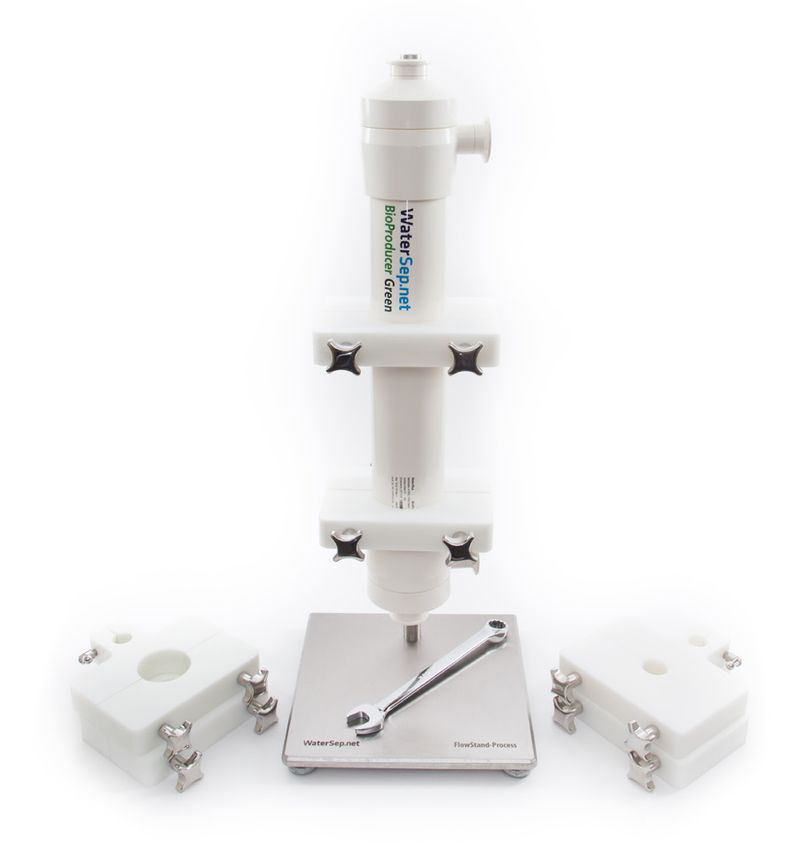
FlowConnector™ Kits, FlowStands™ and FlowSystems
– One Stop Shopping
WaterSep has the hardware you need to complement your cartridge. FlowConnector™ Kits connect your Wa-
terSep cartridge to your tubing assembly, and our FlowStand™ secures your cartridge vertically with custom sized
holders. Our FlowSystems include a console with an embedded PC, pumps, and feed flow and pressure control
capabilities. Let our experts customize a FlowSystem to fit your application.
Additional WaterSep Product Lines
Single Use Green Line
For single use crossflow applications, WaterSep offers gamma irradiated, humectant free and ready to use Green
Line products. The Green Line cartridges require no pre-use flushing and are offered as a single use FlowAssembly™.
ReUse Line
Designed for those applications where cleaning and reuse is acceptable, ReUse Line cartridges can be cleaned,
rinsed, stored and used up to twenty (20x) in the same application.
For questions, contact us at: WaterSep BioSeparations Corporation
experttalk@watersep.net 450 Donald Lynch Boulevard
or call 508-970-0089 Ext 204 Marlborough, MA 01752 USAYou can also read