RF Technologies for the Ground Segment of future Q/V band Satellite Systems - QV-LIFT
←
→
Page content transcription
If your browser does not render page correctly, please read the page content below
RF Technologies for the Ground Segment of future Q/V band Satellite
                                Systems.
  G. Codispoti(1), G. Parca (1), G. Amendola (2), L. Boccia(2), F.Greco(2), G. Goussetis(3), S. Kosmopoulos(3), J.A
  Garcia-Perez(3) M. Siegler(4), C. Riva(5), R. Nebuloni(5), A.Jourier(6), J.Moron(6), R. Eleuteri(7) , F.Massaro(8),
                                           M.Bergmann(8), F.Vitobello(9)
(1)ASI – Agenzia Spaziale Italiana (I), (2)CNIT-Università della Calabria (I), (3)Heriot Watt University (UK),
      (4)ERZIA (S), (5)CNIT- Politecnico di Milano and IEIIT/CNR (I), (6)Ommic (F), (7)Skytech (I),
                                     (8)Eutelsat (F), (9) European Commission

Abstract

This paper presents a summary of the RF systems currently under development for the project: “Q/V
band earth segment LInk for Future high Throughput space systems” (QV-LIFT www.qvlift.eu), that
has recently been awarded funding in the framework of the EU program Horizon 2020. One key
project aims is to develop up to date hardware and software technologies for the Ground Segment of
the future Q/V band terabit Satcom infrastructure. In this paper an account of the developments
related to the RF systems is given.

Introduction

The future High Throughput Satellites (HTS) paradigm has the objective to support the so-called
“Terabit connectivity” thereby bringing to fore requirements for radical changes of technologies. A core
element of envisioned future HTS systems is the use of “beyond Ka-band frequencies”. Q/V band
frequencies (around 40 GHz for downlink and 50 GHz for uplink) are attracting immediate attention
since they offer larger bandwidth availability for the feeder links and opportunities to release
substantial bandwidth in the revenue generating Ka-band. Moreover, Q/V-band offers attrative
bandwidth for specific segments requiring high data rates such as aeronautical in-flight services. The
QV-LIFT project, aims at developing all the hardware and software building blocks for the future Q/V
band Terabit SatCom systems and to integrate them in a way they can be tested in a realistic
scenario. The project started on November 16th 2016 and it will last for about 3 years and it will make
use of the Aldo Paraboni Q/V band payload host by Alphasat. This paper presents an account of the
developments related to the RF building blocks only. A description of the entire project is given in the
companion paper [1].

The QV-LIFT Ground System includes existing and operational earth stations available with the Italian
Space Agency (ASI) and newly built systems. The new systems consist of a mobile TX/RX terminal
and a larger fixed station that are entirely developed by the project consortium. For the systems at
hand, the consortium is currently developing the major building blocks listed in Table I.

                                                      Table I

                                  RF building blocks in development
                     V band MMIC amplifier
                     V band power combining SSPA
                     V band BUC (Block Up Converter)
                     Q band LNB (Low Noise Block down converter)
                     Q/V band (RX/TX) antennas for mobile terminals
                     Q/V band (RX/TX) antenna for fixed station
                     Tracking and pointing systems for the mobile and fixed antennas

As it will be detailed in the following sections, due to the high performance required and to the high
frequency of operation, up to date technologies are needed to realize the components in Table I. As
an example, MMIC are based on the recently delivered OMMIC GaN technology and they are power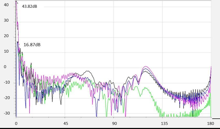
combined in a metallic waveguide divider/combiner to provide a high power SSPA. The LNB is
based on a low noise GaAs LNA produced by OMMIC . The antenna for the mobile terminal is an
Axially Displaced Gregorian reflector with a corrugated feed. This arrangement aims at an aperture
efficiency larger than 70% which ensures good performance in both uplink and downlink. The fixed
earth station is based on a Axially Displaced reflector with a 1.5m diameter. Due to the high
frequencies of operation, antennas require high precision pointing systems. For this reason, the
consortium is developing two tracking systems, one on 3-axis for the antenna mobile terminal and
another one with 2-axis control for the 1.5m antenna.
In the following the components listed in table I will be described giving details of specifications and
showing the intermediate results available.

1. SSPA, BUC and LNB

The SSPA is based on a MMIC GaN amplifier developed in the framework of QV-LIFT. The is on GaN
technology developed by OMMIC. The MMIC specs are reported in table I

                                                Table II

                        Specifications for the V band GaN power amplifier
                  Bandwidth                        47.2-50.2GHz
                  Output Power P2dB                37 dBm (5W)
                  Output Power PSat                39dBm (8W)
                  Gain                             >16dB
                  Gain Flatness                    +- 1.5dB
                  PAE                              20%

The MMIC is being realized with the Ommic D01GH – 100nm process but the 60 nm D006GH has
been also taken in consideration. Notice, that both process are on Silicon and that two MMIC
architectures with three or four stages are considered. Simulated results for Gain, Output Power, DC
Power, Power Added Efficiency are shown in figure 1 for three compression levels (1dB,2dB,3dB).

Figure 1. Simulated Output Parameter of the V band GaN MMIC amplifier under development.

The SSPA power combines 4 MMICs. The power dividing and combined structure is based on 4X1
(1X4) metallic waveguide T magic with low insertion loss shown in figure 2.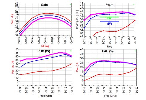
Figure 2. T Magic based 1X4 (4X1) divider/combiner

The power combining/dividing structure is designed to cover the bandwidth from 47.2GHz to 50.2GHz.
The overall architecture of BUC is shown in figure 3 in which components and frequency bands (input,
LO, output) are also shown. The expected overall Gain stays close to 60 dB and the target output
power is 15 W. The BUC has a coax input and a WR22 output and a size of about
200mmX75mmX50mm.

Figure 3. V band Block Up Converter block diagram

Figure 4. Q band Low Noise Block down converter block diagram
The block diagram of the LNB is shown in figure 4 which shows a single stage heterodyne model. The
LNB is based on the CGY2122XUH/C2 LNA developed by OMMIC with NF=1.5dB. The LNB has a
bandwidth from 37.5GHz to 42.5GHz and output Gain > 59 dB. The Noise Figure is 3dB. The overall
size is 100mmX70mmX50mm.
2. Antennas
Link budget analysis [1] indicates the adoption high efficiency antennas. In particular, considering a
link margin larger than 2.5 dB, one needs antennas with G/T > 14dB/K and EIRP > 56 dBW.
Considering antennas with diameters 45cm and 60 cm and the BUC and the LNB presented in the
previous section, one finds that antenna needs to have 70% aperture efficiency which can be
achieved adopting axially displaced reflectors which can maintain very good performance on a large
frequency band.
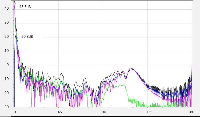
In figure 5 are shown the radiation diagram of the 45 cm antenna at 37.5GHz (RX) and 48.5 GHz (TX).
Also indicated is the maximum gain achieved which is 43.82 dB in RX and 45.5 dB in TX which
correspond to an aperture efficiency close to 80%. The antenna is able to cover from 37GHz to 50
GHz with a good match. Similar results are achieved for the 60 cm antenna which shows 45.9 dB in
RX and 47.7 dB in TX. The 1.5 m antenna is currently under development but preliminary results show
an aperture efficiency of 60% which is already enough to close the link budget thanks to the large
antenna size.
(a)
(b)
Figure 5. Radiation diagram of the 45cm mobile terminal antenna at 37.5GHz (a) and 48GHz (b)3 Tracking Pedestals
Two high precision tracking pedestals are currently under development. The first one is devoted to the
mobile terminal and it has to ensure a high stability while moving. The pedestal is designed following
aeronautical specifications. Some of the specifications are given in table II and table III.
Table II
Tracking pedestal specifications for the mobile terminal
Stabilization axis 3+1 (azimut, elevation, roll + skew angle)
Tracking methods Conical scan, step-track
Pointing error < 0.2°
Azimut range Unlimited
Elevation range 0° ÷ 90°
Roll range -20° ÷ +20°
Skew range -90° ÷ +90°
Table III
Specification for aircraft motion without performance degradation
Yaw rate: ≤ 30 deg/sec
Pitch rate: ≤ 30 deg/sec
Roll rate: ≤ 30 deg/sec
Yaw acceleration : ≤ 40 deg/sec²
Pitch acceleration: ≤ 40 deg/sec²
Roll acceleration: ≤ 40 deg/sec²
Longitudinal velocity (Vx): ≤ 250 m/sec
Lateral velocity (Vy): ≤ 30 m/sec
Vertical velocity (Vz): ≤ 50 m/sec
Longitudinal velocity acceleration: ≤ ± 15 m/sec²
Lateral velocity acceleration: ≤ ± 15 m/sec²
Vertical velocity acceleration: ≤ ± 20 m/sec²
A second tracking pedestal will support the 1.5m antenna and it employs a 2-axis control with
specifications reported in table IV.
Table IV
Tracking pedestal specifications for the fixed station
Motorized axis 2+1 (azimut, elevation + skew)
Pointing error < 0.1°
Azimut range 0° ÷ 360°
Elevation range 0° ÷ 90°
Skew range -90° ÷ +90°4 Conclusions QV-LIFT is a project funded by EU in the framework of the H2020 program which aims to realize all the software and hardware building blocks for the Ground Segment for future Q/V band satellite links. In this paper we have presented the hardware developments which include RF blocks and tracking and pointing systems. As the project is still in its first year, developments are currently at different stages and , for this reason, the results presented are at different levels of detail. However, the paper aimed at introducing the reader to the QV-LIFT developments and to underline the high performance required, the challenges that are currently being faced and limits of the technologies available today. 5 References 1 www.qvlift.eu 2 F.Massaro et al. “QV-LIFT Project: Using the Q/V Band Aldo Paraboni Demonstration Payload for Validating Future Satellite Systems”, 23rd Ka and Broadband Communications Conference, Trieste, Italy, October 16 th-19th, 2017.
You can also read