Georeferencing of Scanned Maps & Spatial Adjustment of Vector Data
←
→
Page content transcription
If your browser does not render page correctly, please read the page content below

Georeferencing of Scanned Maps & Spatial Adjustment of
Vector Data
Georeferencing is the process of assigning spatial coordinates to data that is spatial in
nature, but has no explicit geographic coordinate system. Here, we will take a scanned
paper USGS topographic map and assign spatial coordinates to the image so that it can be
overlaid with modern data. Then, we will use the georeferenced topo map to perform a
spatial adjustment to a streets layer derived from the U.S. Census Bureau’s TIGER Line
Files, which are notoriously inaccurate.
First, download the needed files from:
http://www.library.yale.edu/MapColl/gis_workshop_materials.html,
and extract all of the files to your C:\Temp folder.
Inside the resulting folder you should find the following subfolders & files:
• Georeference_Tutorial
o Georeferencing01.mxd (ArcMap Document) – The main Map Document containing the
files you will use in this tutorial.
o Georeferencing of Scanned Maps.doc (MS Word Document) – The tutorial
documentation for georeferencing.
o Data (Folder)
Scans (Folder)
• New_Haven1984.jp2 (Image) – This is a scan of the USGS 7.5 minute
topographic series map of New Haven, CT. The file format is
JPEG2000 (.jp2), which is an image format that allows compression of
very high resolution imagery to very small file size, and is supported by
ArcGIS.
• New_Haven_1863.jpg (Image) – This is a scan of an 1863 print map
of New Haven from the Yale Map Collection in JPEG (.jpg) format.
Shapefile (Folder)
• NH_UTM18N_NAD27_1000m_Grid (Line Shapefile) – This is a file
created using a tool called Fishnet (Available here at the ESRI
ArcScript Website). It is a Grid of 1000 meter reference graticules in
the UTM projection, using the NAD 1927 Datum.
• NH_Streets_Clipped (Line Shapefile)
Table (Folder)
• NH_Topo_1984_corner_points.csv (Table) – This Comma Separated
Values table contains the corner points of the scanned USGS Topo Map
shown in New_Haven1984.jp2.
Georeferencing of Scanned Maps to a Set of Known Coordinate Points
This first part of the tutorial shows you the steps involved in georeferencing a scanned
map that contains reference ticks or graticules in a known Coordinate System and Datum.
1
1. Open the
                                                       Georeferencing01.mxd
                                                       Map Document included
                                                       with this tutorial.

                                                 Note that you have four layers
                                                 listed in the Table of Contents, but
                                                 only two of the layers are visible.
                                                 This is because the two image
                                                 layers listed do not yet have spatial
                                                 reference.

We will first use the NH_Topo_1984_corner_points.csv file to create a set of corner
points as a reference to provide spatial coordinates to our scanned USGS Topo Map.

2. Uncheck the NH_Street_Clipped & New_Haven_1863.jpg layers to turn off
   their visibility.

3. In the Main Menu, go to View>Toolbars> and turn on the Georeferencing
   Toolbar. If it is floating, you can dock it in the position of your choice.

4. Make sure that the New_Haven_1984.jp2 layer is selected in the Layer: Drop-
   down of the Georeferencing Toolbar.

5. Click on the Georeferencing Button and select Fit
   To Display to bring your New_Haven_1984.jp2
   layer into view.

                                                                                    2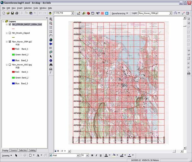
6. Use the Zoom Tool         to zoom
   into the bottom left corner of the
   New_Haven_1984.jp2 layer.
   Note that in some cases, the
   image may be flipped so that you
   have a vertical mirror image of
   the map. You can resolve this by
   clicking on the Georeferencing
   Button and going to Flip or
   Rotate>Flip Vertical.

You should now be able to see that
the scanned image of this 7.5 Topo
map contains information about the
Projection, Coordinate System, Datum and reference grid that the map contains. This
type of information is available on most modern maps created by the USGS and its
international equivalents. This information can be used to prepare the reference files
to be used for georeferencing so that the most accurate result possible is attained. In
this case, reference data (NH_UTM18N_NAD27_1000m_Grid) was created in the
UTM Zone 18n Coordinate System, using the NAD 1927 Datum, since this is the
geographic reference used in the paper map. Likewise, 1000 meter graticules were
used, as in the scanned image, to provide a reference grid comparable to that in the
USGS Topo map. Note that there is more than one reference grid on the USGS Topo
map, but we have chosen the one in meters. Also note that at each corner of the map
image, there are Latitude Longitude Coordinates. These coordinates have been
provided in the CSV file NH_Topo_1984_corner_points.csv.

                                                                                      3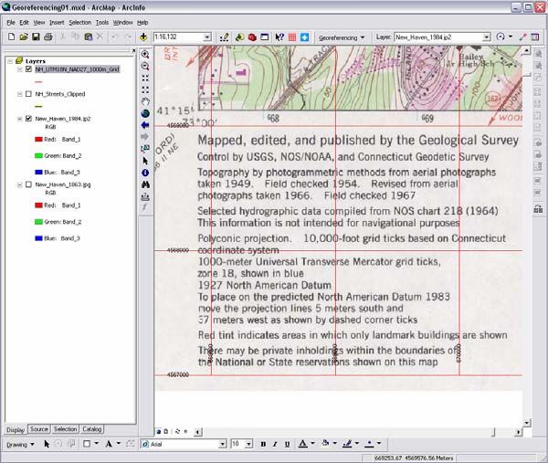
How to Convert Degrees Minutes & Seconds to Decimal Degrees
The NH_Topo_1984_corner_points.csv is a table that contains the latitude & longitude coordinates
of the corners of the topo map you are georeferencing. Since the coordinates of the corners are known,
the simplest means of georeferencing the map is to use these known coordinates. However, the corner
points are recorded on the map in Degrees, Minutes & Seconds format. Before creating the
spreadsheet, these corner coordinates should be converted to Decimal Degrees. Here is an excellent
explanation of how to do that:
(http://www.warnercnr.colostate.edu/class_info/nr502/lg1/notes/dms_and_dd.html). If you want to
work within Excel, here is a tutorial with VB Code (http://support.microsoft.com/kb/213449).

                                                                       7. In the Main Menu,
                                                                          go to
                                                                          Window>Magnifier
                                                                          to open the Magnifier
                                                                          Tool.

                                                                  Note how this tool works, as
                                                                  it is quite useful in
                                                                  georeferencing. We will not
                                                                  actually use it in this tutorial,
                                                                  but you should know about it.

                                                                       8. You can close the
                                                                          Magnifier Tool.

                                         9. Click on the Source Tab at the bottom of the
                                            Table of Contents. Find the
                                            NH_Topo_1984_corner_points.csv table,
                                            which should be at the bottom of the Table of
                                            Contents.

                                         10. Right-Click on the
                                             NH_Topo_1984_corner_points.csv and Open
                                             the table.

                                                                                                    4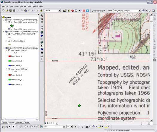
11. Notice that the table contains the Lat/Lon coordinates of the corners of the topo
    map. Close the table.

12. Right-click on the
    NH_Topo_1984_corner_points.csv
    layer and select Display XY Data.

13. In the Display XY Data dialog box,
    click on the Edit… Button, under
    Spatial Reference of Input
    Coordinates.

14. Click on Select… and Browse to
    Geographic Coordinate
    Systems>North America>North
    American Datum 1927.prj. Click
    Add. Click OK twice.

You should now have a set of four points
in your Map Document, to use as
reference points for georeferencing.

15. If you have not already, zoom into the
    lower left corner of the scanned map, so that you can see the corner of the map
    image and the XY point you have added to the map layout.

16. Click on the Georeferencing Button and deactivate the Auto Adjust feature in
    the Georeferencing Toolbar. This will prevent some fairly strange flip-flopping,
    that sometimes happens when adding control point (especially the second one).

17. Activate the Add Control
   Points Tool         on the
   Georeferencing Toolbar
   and Add a control point by
   clicking on the scanned
   map corner first, then click
   on the corresponding
   reference point.
                                                                  Click Here 1st

18. Use the Pan Tool       to
    pan to the lower right
    corner of the map, making
                                                                Click Here 2nd
                                                                                        5
sure that you can also see the reference point and corner at the same time. You
      can use the Fixed Zoom Out Tool         to zoom out until you can see both.

                                                            19. Once again, Activate
                                                                the Add Control
                                                                Points Tool         on
                                                                the Georeferencing
                                                                Toolbar and Add a
                                                                control point by
                                                                clicking on the scanned
                                                                map corner first, then
                                                                click on the
                                                                corresponding reference
                                                                point.

                                                            20. Repeat the preceding
                                                                steps for the remaining
                                                                two reference points.
                                                                Alternating between
      using the Pan Tool      and the Fixed Zoom Out Tool       to adjust your view
      of the map (You could also right-click on the New_Haven_1984.jp2 layer in the
      Table of Contents and Zoom to Layer).

   21. Once all four control points have been added, click on the Georeferencing Button
       and select Update Georeferencing. This will write the spatial coordinates of the
       scanned map to a file that allows you to add the image to ArcMap documents
       along with its geographic referencing.

   22. Zoom into any area along the edge of the scanned map and observe whether the
       blue UTM tick marks on the scanned image are overlaid by the
       NH_UTM18N_NAD27_1000m_Grid. If everything has gone well, they should
       be VERY CLOSE!

Save your work.

                                                                                          6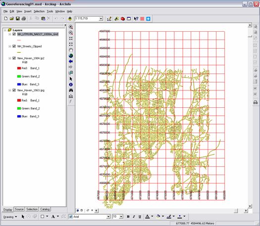
Spatial Adjustment of Vector Data
Not all georeferencing involves applying coordinates to scanned maps. One common
case of georeferencing involves the Spatial Adjustment of the Census Tiger Line Files,
which are not terribly accurate, or in many cases, complete. Here you will use the USGS
Topo map that you have just georeferenced, to spatially adjust the New Haven Tiger
Street Centerlines files.

   1. With your previous
      ArcMap Document
      still open, turn off
      the
      NH_UTM18N_NA
      D27_1000m_Grid
      layer.

   2. Zoom in to the
      lower left corner of
      the scanned map
      image again.

   3. Turn on the
      NH_Streets_Clipp
      ed layer.

   Note that the
   NH_Streets_Clipped streets layer does not line up properly with the streets in the
   topo map we have georeferenced. We will assume that the topo map is correct
   (which is the correct assumption, given the close overlay of the UTM grid) and
   spatially adjust the streets layer.

   4. In the Main Menu, go to View>Toolbars>Editor to open the Editor Toolbar.

   5. Again in the Main Menu, go to
      View>Toolbars>Spatial
      Adjustment to open the Spatial
      Adjustment Toolbar. You can dock both of these toolbars, if you like.

   6. On the Editor Toolbar, click the Editor Button and
      select Start Editing. You will be prompted to select the
      target folder for editing, be sure to select the folder that
      contains the NH_Streets_Clipped shapefile.

                                                                                        7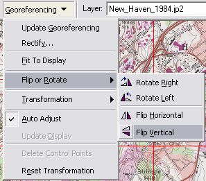
7. Click on the Editor Button and select
      Snapping to open the Snapping
      settings in ArcMap. Find the Vertex
      Column and check the Vertex Box
      next to the NH_Streets_Clipped.
      This will cause the cursor you will
      use to place your control points to
      become “sticky” and to “snap” to the intersections of line segments in your
      NH_Streets_Clipped streets layer. You can close the Snapping Settings Panel
      once you have done this.

   8. On the Spatial Adjustment Toolbar, select the New Displacement Link Tool
           . This tool works very much like the New Control Points Tool in the
       Georeferencing Toolbar.

   9. Just as you did in the previous exercise, begin placing Displacement Links,
      placing the first link on an intersection in the NH_Streets_Clipped layer, and the
      second link on the corresponding intersection in the topo map.

You won’t be “warping” the streets layer in this case, but simply shifting the file, since it
is evident that there is some systematic inaccuracy in the spatial referencing of the streets,
relative to the topo map. In most cases, it is best to spread your Control Points, or
Displacement Links across as wide an area of your data as possible. In this case, we
want to place a Displacement Link at
each corner of the topo map, as well as
one Displacement Link at the center of
the map.

   10. Continue placing Displacement
       Links, zooming and panning
       across the extent of the topo map,
       until you have placed four links
       at the corners and one at the
       center of the map.

   11. In the Spatial Adjustment
       Toolbar, click on the Spatial
       Adjustment Button and select
       Set Adjust Data.

                                                                                            8
12. Check the “All features in these layers:” Radio Button and Check the
NH_Streets_Clipped layer. Click OK.
13. Again, in the Spatial Adjustment Toolbar, click on the Spatial Adjustment
Button and select Adjust.
14. Zoom into any area of the map and note that you should now have slightly better
overlay of your NH_Streets_Clipped streets layer with the
New_Haven_1984.jp2 topo map.
Save your work.
Note that the overlay
will still not be perfect.
The TIGER Line Files
were created for
describing the
boundaries of Census
Geography units, rather
than the true centerline
positions of streets.
Without some fairly
extensive editing, the
TIGER line files will
never be perfect. This
is one of the reasons
that there is a growing
industry built around
producing higher
accuracy & precision
street centerline files.
Many municipalities are
producing, or
contracting for the
production of, their own street line files. If you need highly accurate street files, you
may want to explore the possibility of obtaining them from sources other than the
U.S. Census Bureau.
Independent Exercise
Included with this tutorial is an additional image file of an 1863 map of New Haven,
CT. Using you corrected streets layer, NH_Streets_Clipped, and the methods you
learned in the first part of the tutorial, georeference this historic map of New Haven,
so that it can be overlaid with modern data.
9You can also read