STEM LEARNING: Advanced Air Mobility: Rubber Band Helicopter Engineering Challenge Student Guide - NASA
←
→
Page content transcription
If your browser does not render page correctly, please read the page content below

National Aeronautics and Space Administration

STEM LEARNING:
Advanced Air Mobility: Rubber
Band Helicopter Engineering
Challenge Student Guide
www.nasa.gov
2 | ADVANCED AIR MOBILITY: RUBBER BAND POWERED HELICOPTER ENGINEERING CHALLENGE (STUDENT GUIDE)
PART 1
Imagine looking out your window and seeing a taxi fly by. Or, imagine you could go into your backyard and a drone
would be delivering food from a local restaurant. These may seem like something from a science fiction movie or cartoon,
but it isn’t as farfetched as you might think. Within the next few years, people will actually be riding in flying taxis! And, in
some places, drones are already making deliveries.
With this revolutionary new type of aviation comes the need to monitor and control the airspace they fly in. NASA is
working with its partners to develop a system called Advanced Air Mobility (AAM). This system helps monitor and control
the movements of small, low-flying aircraft, such as drones and air taxis operating in both urban and rural areas. To
minimize their environmental impact, these aircraft are electrically powered and use propellers to create both lift to move
up and thrust to move forward.
In this activity, you will explore how propellers create lift and the resulting torque that is also created. You will be
designing the body, or fuselage, of a helicopter to minimize the effect of torque.
Read through the background information below and answer the questions that follow it.
BACKGROUND INFORMATION
Newton’s Third Law of Motion
Sir Isaac Newton came up with three laws to describe
the motion of objects. His third law states that for every
action there is an equal and opposite reaction. We see
this law in action frequently. For example, if an inflated
balloon is released, the air comes out one end and the
balloon moves in the opposite direction. The escaping
air is the action, and the movement of the balloon is the
equal and opposite reaction.
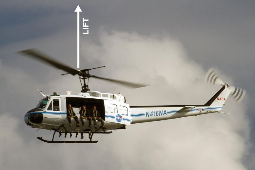
Newton’s third law also applies to rotary winged
aircraft, such as helicopters or drones, because their
spinning blades create both lift and torque. The blades
on a helicopter or drone create a downward force by
pushing the air down. The equal and opposite force is
the upward force of lift. Assuming lift is a stronger force
Figure 1. The blades on a helicopter create lift that moves it than the gravity, it moves the aircraft up.
upward. Credit: NASA/ Dan Casper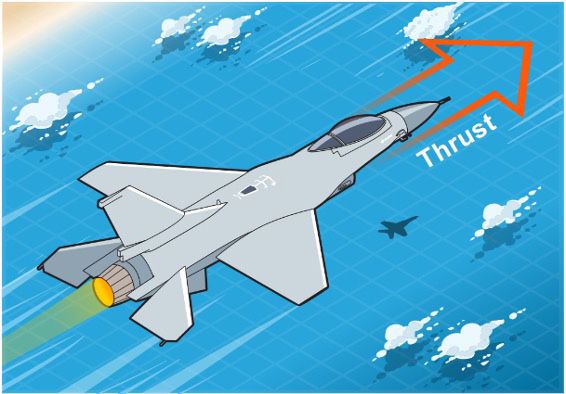
ADVANCED AIR MOBILITY: RUBBER BAND POWERED HELICOPTER ENGINEERING CHALLENGE (STUDENT GUIDE)                        | 3

                                                               Torque
                                                               In addition to lift, a rotating propeller creates a force in
                                                               the direction it rotates. According to Newton’s third law of
                                                               motion, there must also be an equal and opposite force.
                                                               This force, called torque, acts in the direction opposite of
                                                               the propeller’s rotation. As shown in figure 2, when the
                                                               blades rotate clockwise, the torque acts in the opposite
                                                               direction, counterclockwise. If left unbalanced, the torque
                                                               causes the fuselage of the helicopter to rotate. Engineers
                                                               have devised several ways to compensate for torque. In
                                                               the helicopter shown in figure 2, the tail rotor creates a
                                                               force to balance out the torque which keeps the fuselage
                                                               from rotating.

Figure 2. The force created by the tail rotor balances out
the torque.

Propellers
Unmanned Aerial Vehicles, or UAVs, usually fly below 400
feet, are electrically powered, and use rotating propellers
to provide both lift and thrust. The propeller size varies
according to the size of the aircraft. Small package
carrying drones only require small, relatively slow
propellers whereas larger air taxis require larger, faster
rotating ones. Propellers on some larger aircraft are even
capable of being rotated to provide lift like a helicopter’s
blades or thrust like an airplane’s propeller.

                                                               Figure 3. On some aircraft, the propellers can rotate to
                                                               provide upward lift or forward thrust. Credit: NASA

                                                               Relative to the direction an aircraft is moving, propeller
                                                               blades are angled. The angle, or pitch, of the blades
                                                               determines the direction the air is pushed. The speed at
                                                               which the propellers rotate, along with the pitch of the
                                                               blades, determines how much air is pushed.

                                                               Reversing the direction of a propeller’s rotation reverses
                                                               the direction the air is pushed. Think of it like a screw—if it
                                                               is turned in one direction, it moves down; and if it is turned
                                                               the other way, it moves up.

Figure 4. This computer simulation shows the movement
of air caused by the rotating of a quadcopter’s propellers.
Credit: Seokkwan Yoon, NASA/Ames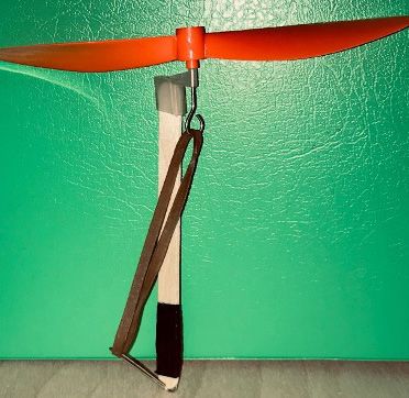
4 |     ADVANCED AIR MOBILITY: RUBBER BAND POWERED HELICOPTER ENGINEERING CHALLENGE (STUDENT GUIDE)

QUESTIONS
1.   Explain how the plane shown in figure 5 demonstrates
     Newton’s third law of motion.

                                                             Figure 5. Hot gases coming out the back of a jet
                                                             create thrust. Credit: NASA

2. The V-22 Osprey is an aircraft that creates lift using
   two propellers that tilt to face upwards. Keeping in
   mind that propellers create torque, how is it possible
   that this aircraft can operate without a tail rotor?
   (Hint: Look closely at the propeller blades in figure 6
   and think about what you learned about pitch in the
   Background Information.)

                                                             Figure 6. The V-22 Osprey can tilt its rotors up for
                                                             takeoff and landing. Credit: U.S. Navy photo by Mass
                                                             Communication Specialist 3rd Class Vincent E. Zline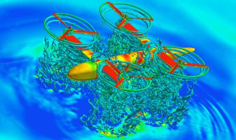
ADVANCED AIR MOBILITY: RUBBER BAND POWERED HELICOPTER ENGINEERING CHALLENGE (STUDENT GUIDE)                         | 5

PART 2
Build Your Helicopter

Materials needed: craft stick, propeller, paper clip, rubber band, piece of
cardstock, pair of scissors, ruler, and tape.

Directions:
1. Gather all materials.
2. Bend paper clip so it forms about a 45 degree angle.
3. Using tape, attach paper clip to one end of the craft stick.
4. Attach propeller to other end of the craft stick.
 5. Attach rubber band to both the propeller and the paper clip.
6. Cut out pieces of cardstock, one for each of the following centimeter (cm)
     dimensions:
     a 3 cm x 4 cm
     b. 6 cm x 8 cm
     c. 9 cm x 12 cm                                                                  Figure 7. Completed helicopter before
     d. 12 cm x 16 cm                                                                 attaching fuselage.

Conduct Baseline Testing

In part 1 of this activity, you learned that there must be a force counteracting the torque created by the rotating
propellers. The helicopter you just built doesn’t have a tail rotor to create this counteracting force. Because your
helicopter is so small and light, you will be using air resistance to counteract the torque.

If left unbalanced, the torque causes the craft stick to rotate, using too much energy and making it difficult for your
helicopter to fly. So, you will be adding a fuselage in the form of a piece of cardstock. The size of your fuselage
determines the amount of air resistance—the larger the fuselage, the more air resistance it creates.

Directions:
1. Wind the propeller clockwise about 20 rotations and let the propeller go while still holding the helicopter, noting
    which direction the propeller pushes the air.
2. Repeat step 1, but rotate the propeller counterclockwise this time.
3. For the remainder of this activity, always rotate the propeller in the direction that results in the propeller pushing the
    air downward.
4. With no paper attached to craft stick, wind the propeller 35 rotations and let the helicopter go.
5. Record what you observe.
6. Repeat steps 4 and 5 for a total of three trials.
7. One at a time, attach each piece of cardstock to the helicopter, wind it 35 times, let the helicopter go, and record
    what you observe. Conduct three trials with each sized piece of cardstock. After completing the trials, remove the
    cardstock before attaching the next piece.

Hypothesize:
How does the size of the fuselage (piece of paper attached to the craft stick) affect the performance of the helicopter?
Why?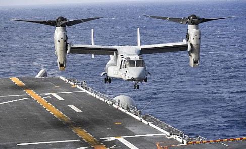
6 |     ADVANCED AIR MOBILITY: RUBBER BAND POWERED HELICOPTER ENGINEERING CHALLENGE (STUDENT GUIDE)

PART 3
      Your Goal: Modify your helicopter so that it will rise between 1.5 and 2.0 meters after being launched.

      Criteria: Your helicopter should rise at least 1.5 meters and no more than 2.0 meters.

      Constraints: After designing, building, and testing your prototype, you may change one factor.

Ask

What factors can be changed on your helicopter to affect how high it rises?

After you list the factors you can think of, brainstorm with your group or class to develop a list of factors that may be
changed during the improve stage. List the factors your class brainstormed: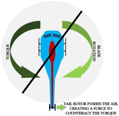
ADVANCED AIR MOBILITY: RUBBER BAND POWERED HELICOPTER ENGINEERING CHALLENGE (STUDENT GUIDE)                | 7

Imagine / Plan

Determine the size and shape of your fuselage (piece of cardstock) and how many times you plan on winding the
propeller. Sketch your design below and label the size. Then, indicate how many rotations you will wind it:

                                                                              Wind it __________________rotations.

Create / Experiment

Directions:

1. With your group, agree upon a design. Then, cut out the fuselage you planned and attach it.
2. Conduct up to three test flights to judge your helicopter’s performance.
8 | ADVANCED AIR MOBILITY: RUBBER BAND POWERED HELICOPTER ENGINEERING CHALLENGE (STUDENT GUIDE) Answer: How well did your helicopter perform and did it perform approximately the same during each test flight? From the list of factors your class agreed upon, choose one factor that you think should be adjusted on your design. Which factor did you choose, how will you modify it, and why did you choose that factor? Improve Modify your design by changing only one factor.
ADVANCED AIR MOBILITY: RUBBER BAND POWERED HELICOPTER ENGINEERING CHALLENGE (STUDENT GUIDE)                 | 9

Share

Share your design with the class. Explain why you designed it as you did. Then, explain what factor you changed and
why. After sharing, conduct your final flight.

Answer the following questions individually:

What worked well with your design?

What other factor(s) would you change if you could?

What design features did you see in the other teams’ helicopters that you thought were especially good?
National Aeronautics and Space Administration
Headquarters
300 E Street SW
Washington, DC 20546

EP-2020-04-511-HQ
You can also read