ANSI/SCTE 146 2021 AMERICAN NATIONAL STANDARD - Outdoor "F" Female to "F" Female Inline Splice
←
→
Page content transcription
If your browser does not render page correctly, please read the page content below
Interface Practices Subcommittee

     AMERICAN NATIONAL STANDARD

            ANSI/SCTE 146 2021

Outdoor “F” Female to “F” Female Inline Splice
ANSI/SCTE 146 2021
NOTICE
The Society of Cable Telecommunications Engineers (SCTE) Standards and Operational Practices
(hereafter called “documents”) are intended to serve the public interest by providing specifications, test
methods and procedures that promote uniformity of product, interoperability, interchangeability, best
practices, and the long term reliability of broadband communications facilities. These documents shall not
in any way preclude any member or non-member of SCTE from manufacturing or selling products not
conforming to such documents, nor shall the existence of such standards preclude their voluntary use by
those other than SCTE members.
SCTE assumes no obligations or liability whatsoever to any party who may adopt the documents. Such
adopting party assumes all risks associated with adoption of these documents and accepts full
responsibility for any damage and/or claims arising from the adoption of such documents.
NOTE: The user’s attention is called to the possibility that compliance with this document may require
the use of an invention covered by patent rights. By publication of this document, no position is taken
with respect to the validity of any such claim(s) or of any patent rights in connection therewith. If a patent
holder has filed a statement of willingness to grant a license under these rights on reasonable and
nondiscriminatory terms and conditions to applicants desiring to obtain such a license, then details may
be obtained from the standards developer. SCTE shall not be responsible for identifying patents for which
a license may be required or for conducting inquiries into the legal validity or scope of those patents that
are brought to its attention.
Patent holders who believe that they hold patents which are essential to the implementation of this
document have been requested to provide information about those patents and any related licensing terms
and conditions. Any such declarations made before or after publication of this document are available on
the SCTE web site at https://scte.org.
All Rights Reserved
© Society of Cable Telecommunications Engineers, Inc. 2021
140 Philips Road
Exton, PA 19341
AMERICAN NATIONAL STANDARD © SCTE 2ANSI/SCTE 146 2021
Table of Contents
Title Page Number
NOTICE ......................................................................................................................................................... 2
Table of Contents .......................................................................................................................................... 3
1. Introduction.......................................................................................................................................... 4
1.1. Executive Summary ............................................................................................................... 4
1.2. Scope ..................................................................................................................................... 4
1.3. Benefits .................................................................................................................................. 4
1.4. Intended Audience ................................................................................................................. 4
1.5. Areas for Further Investigation or to be Added in Future Versions........................................ 4
2. Normative References ........................................................................................................................ 4
2.1. SCTE References .................................................................................................................. 5
2.2. Standards from Other Organizations ..................................................................................... 5
2.3. Published Materials ................................................................................................................ 5
3. Informative References ....................................................................................................................... 5
3.1. SCTE References .................................................................................................................. 5
3.2. Standards from Other Organizations ..................................................................................... 5
3.3. Published Materials ................................................................................................................ 5
4. Compliance Notation ........................................................................................................................... 6
5. Abbreviations and Definitions.............................................................................................................. 6
5.1. Abbreviations.......................................................................................................................... 6
5.2. Definitions............................................................................................................................... 6
6. Mechanical .......................................................................................................................................... 7
6.1. Dimensions............................................................................................................................. 7
6.2. Center Conductor Mating and Retention Force ..................................................................... 7
7. Electrical .............................................................................................................................................. 7
7.1. Bandwidth............................................................................................................................... 7
7.2. Insertion Loss / Return Loss .................................................................................................. 7
7.3. Shielding Effectiveness .......................................................................................................... 8
7.4. Surge Withstand ..................................................................................................................... 8
7.5. Center Conductor Contact Resistance .................................................................................. 8
7.6. Outer Conductor Contact Resistance .................................................................................... 8
7.7. Current Carrying Capacity...................................................................................................... 8
8. Environmental ..................................................................................................................................... 8
8.1. Salt Spray ............................................................................................................................... 8
8.2. Temperature ........................................................................................................................... 8
9. Dimensions.......................................................................................................................................... 9
List of Figures
Title Page Number
Figure 1 – Dimensions .................................................................................................................................. 9
List of Tables
Title Page Number
Table 1 – Insertion Loss / Return Loss ......................................................................................................... 7
Table 2 – Descriptions of Dimensions .......................................................................................................... 9
AMERICAN NATIONAL STANDARD © SCTE 3ANSI/SCTE 146 2021
1. Introduction
1.1. Executive Summary
This specification provides the mechanical and electrical performance of the outdoor “F” inline splice that
provides uniform “F” port lengths for proper sealing in outdoor environments.
1.2. Scope
The purpose of this document is to specify mechanical and electrical standards for 75 ohm broadband
radio frequency (RF) devices whose purpose is to provide an outdoor inline connection between two type
“F” male connectors that conform to ANSI/SCTE 123; Specification for “F” Connector, Male, Feed-
Through or ANSI/SCTE 124; Specification for “F” Connector, Male, Pin Type and ANSI/SCTE 160,
Specification for Mini “F” Connector, Male, Pin Type. The mechanical configuration is designed to
accommodate sealing rings for external applications.
DOCSIS 4.0 specifications include operation at frequencies up to 1794 MHz and many service providers
would like to futureproof their networks for eventual operation up to 3000 MHz.
The outdoor “F” splice is capable of 3000 MHz operation but, is typically used to connect two “F” male
connectors and associated cable together. The bandwidth performance of the “F” splice is dependent on
the components to which it is attached.
1.3. Benefits
This specification is necessary to provide manufacturers and users of this product a basic set of standard
dimensional and performance requirements from which to gauge design performance.
It’s useful for cable and equipment manufacturers to ensure proper mating with varied connector
manufactured designs. This specification provides confidence to end users that designs which meet these
minimum criteria will perform properly in their systems.
1.4. Intended Audience
Manufacturers, test laboratories, and end-users.
1.5. Areas for Further Investigation or to be Added in Future Versions
None
2. Normative References
The following documents contain provisions, which, through reference in this text, constitute provisions
of this document. At the time of Subcommittee approval, the editions indicated were valid. All documents
are subject to revision; and while parties to any agreement based on this document are encouraged to
investigate the possibility of applying the most recent editions of the documents listed below, they are
reminded that newer editions of those documents might not be compatible with the referenced version.
AMERICAN NATIONAL STANDARD © SCTE 4ANSI/SCTE 146 2021
2.1. SCTE References
• ANSI/SCTE 04 2020, Test Method for “F” Connector Return Loss
• ANSI/SCTE 05 2020, Test Method for “F” Connector Return Loss In-Line Pair
• ANSI/SCTE 48-1 2015, Test Method for Measuring Shielding Effectiveness of Passive and
Active Devices Using a GTEM Cell
• ANSI/SCTE 81 2018 Surge Withstand Test Procedure
• ANSI/SCTE 103 2018, Test Method for DC Contact Resistance, Drop Cable to F- Connectors and
F81 Barrels
• ANSI/SCTE 123 2020 Specification for “F” Connector, Male, Feed-Through
• ANSI/SCTE 124 2020, Specification for “F” Connector, Male, Pin Type
• ANSI/SCTE 143 2018, Test Method for Salt Spray
• ANSI/SCTE 144 2017, Test Procedure for Measuring Transmission and Reflection
• ANSI/SCTE 160 2018, Specification for Mini ‘F’ Connector, Male, Pin Type
• SCTE 269 2021, Test Procedure for “F” Port Center Conductor Retention Force
2.2. Standards from Other Organizations
• No normative references are applicable.
2.3. Published Materials
• No normative references are applicable.
3. Informative References
The following documents might provide valuable information to the reader but are not required when
complying with this document.
3.1. SCTE References
• No informative references are applicable.
3.2. Standards from Other Organizations
• No informative references are applicable.
3.3. Published Materials
• No informative references are applicable.
AMERICAN NATIONAL STANDARD © SCTE 5ANSI/SCTE 146 2021
4. Compliance Notation
This word or the adjective “required” means that the item is an
shall
absolute requirement of this document.
This phrase means that the item is an absolute prohibition of this
shall not
document.
forbidden This word means the value specified shall never be used.
This word or the adjective “recommended” means that there may exist
valid reasons in particular circumstances to ignore this item, but the
should
full implications should be understood and the case carefully weighted
before choosing a different course.
This phrase means that there may exist valid reasons in particular
circumstances when the listed behavior is acceptable or even useful,
should not
but the full implications should be understood and the case carefully
weighed before implementing any behavior described with this label.
This word or the adjective “optional” means that this item is truly
optional. One vendor may choose to include the item because a
may
particular marketplace requires it or because it enhances the product,
for example; another vendor may omit the same item.
Use is permissible for legacy purposes only. Deprecated features may
deprecated be removed from future versions of this document. Implementations
should avoid use of deprecated features.
5. Abbreviations and Definitions
5.1. Abbreviations
lb pound
in inch
mm millimeter
DC direct current
lb-in pound inch
MHz megahertz
Hz hertz
ISBE International Society of Broadband Experts
SCTE Society of Cable Telecommunications Engineers
5.2. Definitions
thread relief A reduced diameter section of the threaded surface to allow the tool to
run out. This feature is optional.
center conductor The inner conductor of a coaxial port, cable or pin of mating male
connector.
mating male center conductor The distance from the reference plane of the female “F” port to which
clearance the center conductor of the mating male connector may penetrate
without damaging the port or encountering a blockage.
positive contact point The distance from the reference plane of the female “F” port to the
first point of contact in the female center contact when the installed
mating center conductor is centered.
AMERICAN NATIONAL STANDARD © SCTE 6ANSI/SCTE 146 2021
reference plane The reference plane on the female outdoor “F” port is the mating
surface that seats against the male “F” port. It is also the plane from
where all horizontal dimensions are taken.
parting line (relevant to A raised mark left on the surface of a part as a result of the gap
casting process only) between two halves of a die.
6. Mechanical
6.1. Dimensions
The physical dimension of the inline splice shall meet the dimensional requirements specified in Figure 1,
Table 2, and the notes below Table 2.
6.2. Center Conductor Mating and Retention Force
The center conductor port of both ends shall accept male “F” connector center conductors whose
diameters are between 0.030 inches (0.76 mm) and 0.042 inches (1.066 mm). The center conductor port
of both ends shall meet the requirements of SCTE 269 2021.
7. Electrical
7.1. Bandwidth
All devices shall be designed to operate over a bandwidth of 5 MHz to 3000 MHz with an impedance of
75 ohms.
7.2. Insertion Loss / Return Loss
The insertion loss of the device, measured from the input port to the output port, shall not exceed the
values in Table 1 when tested in accordance to ANSI/SCTE 144, Test Procedure for Measuring
Transmission and Reflection.
The return loss, as measured at either RF port, with the other port terminated into 75 ohms, shall meet the
requirements listed in Table 1 when mated with cables of size 6-series and/or 11-series, which meet the
requirement of ANSI/SCTE 74 and which have male “F” connectors meeting and installed in accordance
with ANSI/SCTE 123 for 6-series cables or ANSI/SCTE 124 for 11-series cables. All measurements
should be made in accordance with the procedures outlined in ANSI/SCTE 144.
ANSI/SCTE 04 and/or ANSI/SCTE 05 may be used as guidance in conducting these measurements.
All electrical specifications shall apply to both ports and either signal flow direction.
Table 1 – Insertion Loss / Return Loss
Frequency (MHz) Insertion Loss (dB) Return Loss (dB)
5 - 1002 ≤ 0.05 ≥ 30
1002 - 1218 ≤ 0.05 ≥ 30
1218 - 1794 ≤ 0.10 ≥ 25
1794 - 2250 ≤ 0.15 ≥ 20
2250 - 3000 ≤ 0.20 ≥ 18
AMERICAN NATIONAL STANDARD © SCTE 7ANSI/SCTE 146 2021
7.3. Shielding Effectiveness
When the outdoor inline splice interface is attached to cables manufactured to SCTE approved standards
with connectors manufactured and installed per SCTE approved standards, the assembly shall meet
shielding performance levels of an unspliced section of the same cable within a +/- 3 dB tolerance when
both are tested with the same method. One of the methods used for this testing shall be ANSI/SCTE 48-3,
Test Procedure for Measuring Shielding Effectiveness of Coaxial Cable and Connectors Using the GTEM
Cell.
7.4. Surge Withstand
The surge withstand, when measured in accordance with ANSI/SCTE 81, shall be a minimum of IEEE
C62.41-1991 Category A3 Ring Wave, 6 KV, 200 ampere.
7.5. Center Conductor Contact Resistance
After being stressed per the procedure in section 9.1 of SCTE 269 2021, the center conductor junction of
the female to male “F” center conductor shall have a DC contact resistance of less than 25 milliohms
when tested in accordance to ANSI/SCTE 103 with a 0.0320 inch (0.812 mm) diameter center conductor.
7.6. Outer Conductor Contact Resistance
The outer conductor junction of the outdoor female “F” port to male F connector shall have a DC contact
resistance less than 10 milliohms when tightened to 40 lb.-in. and tested to ANSI/SCTE 103.
7.7. Current Carrying Capacity
The center conductor junction of the outdoor female “F” port to male “F” center conductor shall be
capable of carrying a minimum of 1 ampere DC continuous current at an ambient temperature of 40 °C
without degradation.
8. Environmental
8.1. Salt Spray
Components shall meet the electrical performance as outlined in section 7, after 1000 hours of the salt
spray when tested in accordance to ANSI/SCTE 143.
8.2. Temperature
The devices shall meet all performance requirements during and after exposure to temperatures ranging
from -40 °F (-40 °C) to +140 °F (+60 °C) as per ANSI/SCTE 158, Class 1, Condition A.
The temperature cycle shall be:
1. 2 hours at low limit
2. 1 hour transition to high limit
3. 2 hours at high limit
4. 1 hour transition to low limit
5. Repeat for 15 cycles
AMERICAN NATIONAL STANDARD © SCTE 8ANSI/SCTE 146 2021
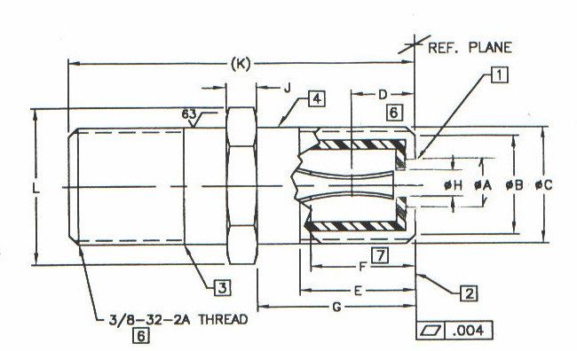
9. Dimensions
Figure 1 – Dimensions
Table 2 – Descriptions of Dimensions
DESCRIPTION DIM mm inches NOTES
min max Min max
Reference Plane Opening Diameter A 4.32 6.10 0.170 0.240
Reference Plane Outer Diameter B 7.11 8.00 0.280 0.315
Base Outer Diameter C 9.35 9.65 0.368 0.380
Positive Contact Point Depth D - 5.08 - 0.200 5
Full Thread Depth E 8.26 8.89 0.325 0.350
Mating Male Center Conductor Clearance F 9.65 - 0.380 - 7
Port Length G 12.07 13.21 0.475 0.520
Center Conductor Guide Inner Diameter H - 1.73 - 0.068
Length J 2.29 - 0.090 -
Over All Length (Reference) K 27.67 - 1.090 -
Maximum Crown Envelope Dimension L - 16.58 - 0.653
Notes:
1. No material shall impede the entry of the male connector.
2. Reference Plane
3. Thread relief not to exceed 1 full thread.
4. Finish required for port seal ring.
5. Dimension to point of positive contact of terminal.
6. ANSI specification B1.1 (Major DIA 0.368/0.374)
7. Minimum clearance for maximum center conductor.
8. Recommended Mating Male Center Conductor Diameter Range is 0.030 in. (0.76 mm) Min. to
0.042 in. (1.066 mm) Max.
9. All Dimensions Typical, unless specified.
AMERICAN NATIONAL STANDARD © SCTE 9You can also read