ASSESSMENT AND REMEDIATION OF A NON-AQUEOUS PHASE LIQUID HYDROCARBON PLUME IN FRACTURED BEDROCK - Ian Mitchell, M.Sc. P.Geo
←
→
Page content transcription
If your browser does not render page correctly, please read the page content below
ASSESSMENT AND REMEDIATION
   OF A NON-AQUEOUS PHASE
LIQUID HYDROCARBON PLUME IN
     FRACTURED BEDROCK

              Ian Mitchell, M.Sc. P.Geo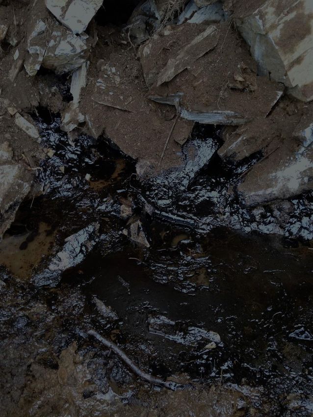
Outline

•   Background and Site Description
•   Challenges of Assessment in Bedrock
•   Fracture Flow Dynamics
•   Fracture Mapping / Characterization
•   Structural Geology Interpretation
•   Developing Delineation Targets
•   Remediation
Site Location
Site Setting
      N   Site is a former fuel oil depot
          at the Department of National
          Defense Colwood, BC
          Area under environmental
          investigation

          Former fuel oil storage tanks,
          including a tank that held
          40,000 barrels of Bunker C
          product located directly up
          gradient at higher elevation.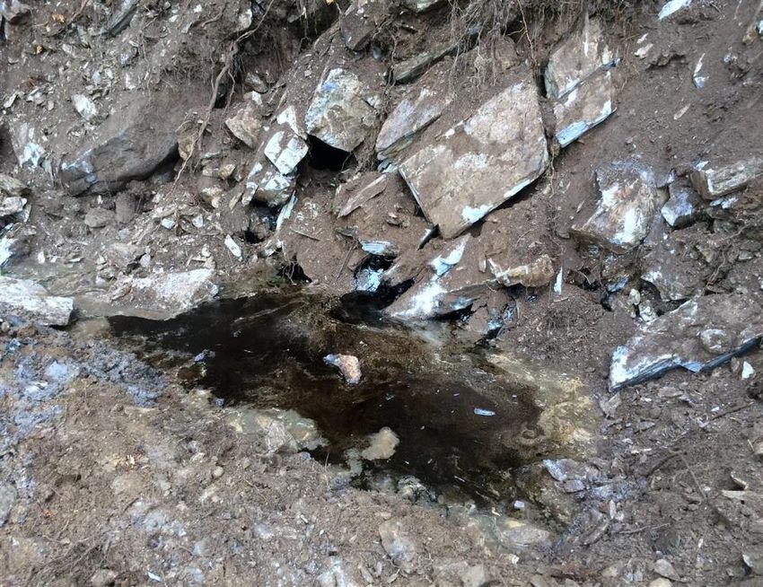
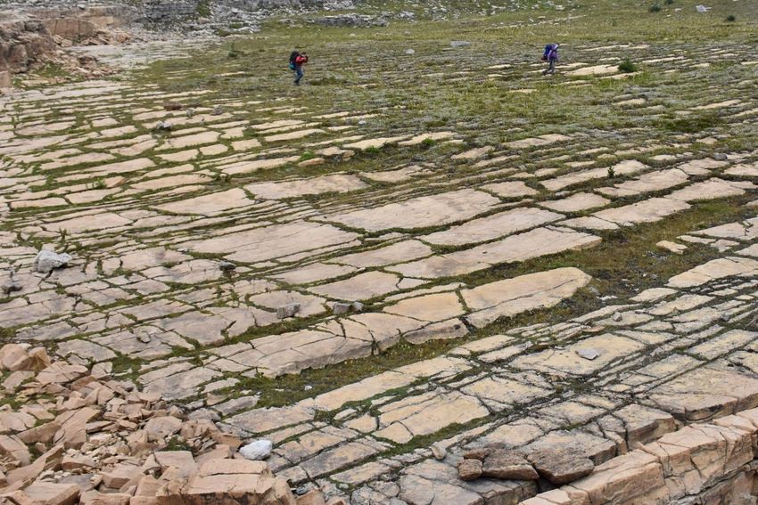
Site Setting
      N   Moderately steep topography
          northward below the former
          tank farm
          Numerous bedrock outcrops
          within treed areas

          Groundwater flow towards the
          north

          Site access road extended to
          create additional drill pads for
          investigation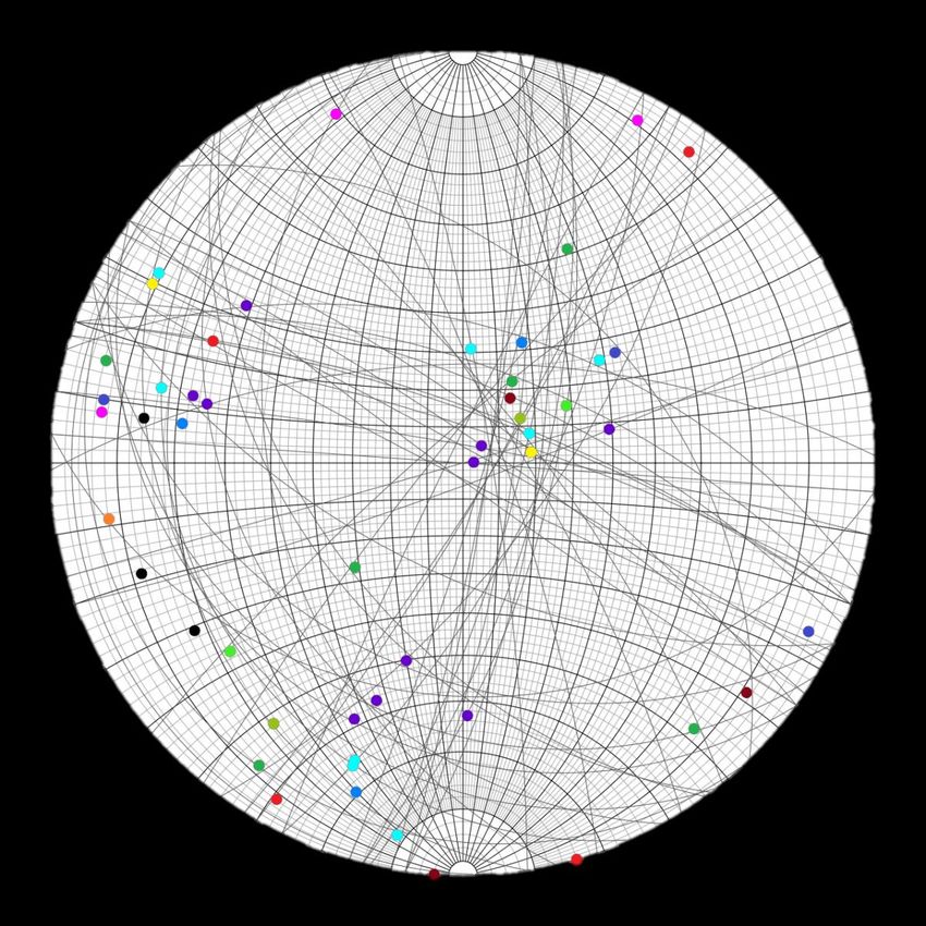
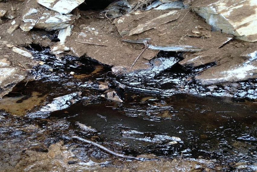
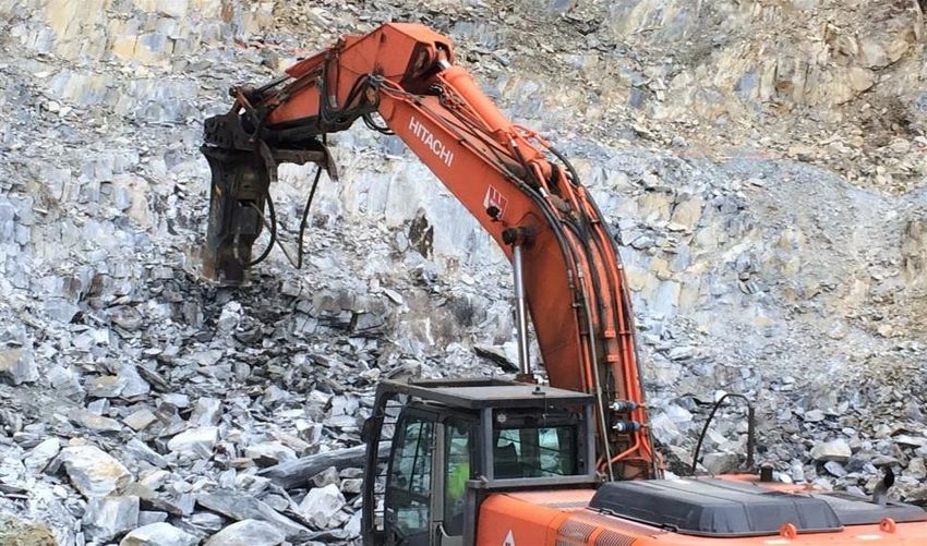
Background
During road construction, a heavy-end non-aqueous liquid (NAPL)
hydrocarbon product was observed oozing from fractures in a
freshly excavated rock face
Background
During road construction, a heavy-end non-aqueous liquid (NAPL)
hydrocarbon product was observed oozing from fractures in a
freshly excavated rock face
NAPL in Fractures
Background
• Impacted bedrock was dammed with sawdust, lined with a
  poly barrier and temporarily backfilled until an appropriate
  course of action could be determined

• Source of product unknown; former up gradient Bunker C
  tank considered likely

• However, prior assessment conducted in the tank farm area
  found no significant evidence of contamination

• Anecdotal information that a small asphalt manufacturing
  facility may have operated in the area several decades
  earlier; location unknown.
Site Bedrock Assessment
Significant number of bedrock outcrops on and off site

            NAPL

Recognized as an opportunity to gather cost-effective
information on bedrock structures
Fracture Flow Dynamics • Flow through bedrock can be significantly more complex than flow through unconsolidated materials • Fractures can introduce significant heterogeneity • Flow through unconsolidated materials governed by their hydraulic conductivity, porosity and hydraulic gradients • Flow through bedrock also depends on density and connectivity of fractures, their aperture and orientation • A sufficiently dense network of fractures that are well connected may behave like an unconsolidated porous medium
Fracture Flow Dynamics
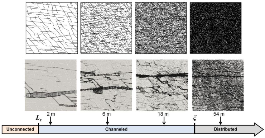
Courtesy of Solidity ProjectFracture Flow – Scale Dependency
Courtesy of ITRCFracture Flow – Scale Dependency
Fracture Flow – Scale Dependency

   1 km
Fracture Mapping

Planes such as fractures, stratigraphic bedding and other structural
features – we describe their orientation by strike and dip
Fracture Flow Dynamics

                                                Courtesy of ITRC

NAPL adds additional complexity – multiphase flow
Fracture Flow Dynamics
Courtesy of SABCS
Fractures often act as preferential pathways that can transmit
contamination cross gradientFracture Flow Dynamics Primary porosity versus Dual Porosity
Site Bedrock Assessment

                                       Geophysics Survey Grid

Bedrock outcrops catalogued and individually mapped for
fracture orientations, unit contacts, other structural features
Geophysics Survey
A seismic refraction survey was
completed to determine subsurface
bedrock topography to assist with
delineation and remediationFracture Mapping
Fracture Mapping Assessment Colwood FOD, Colwood, BC
Compass and Inclinometer GeoID Output
Dip Dip
Area Strike (N) Dip NAPL Strike (N) Dip
Orientation Orientation
1 161 79 E - 341 79 E
1 148 75 E - 328 75 NE
1 188 76 E - 8 76 E
2 117 86 W - 117 86 SW
2 70 84 SE - 70 84 S
2 8 83 E - 8 83 E
3 36 66 E Y 36 66 SE
3 106 53 N Y 286 53 N
3 110 63 N Y 290 63 N
3 194 68 E Y 14 68 E
3 89 63 N Y 269 63 N
3 113 68 N - 293 68 NE
3 193 65 E - 13 65 E
3 167 40 W - 167 40 W
3 137 7 S Y 137 7 SW
3 176 3 W - 176 3 W
4 290 75 N Y 290 75 NStereonet Analysis • When a plane is projected • All planes have a unique axis, within a sphere, its intersection or pole, that is 90o to the with the sphere surface forms surface of the plane; plots as a an arc unique to that plane point on the sphere surface
Stereonet Analysis
     N

                  Stereographic projections
                  are analytical tools routinely
                  used by geologists to
                  analyze planar features
W             E
                  Plotting the poles generally
                  makes observation of
                  relationships between
                  features easier to distinguish

     S
Stereonet Analysis
Composite Fracture Analysis
          N
                        All Outcrop Areas
                                         No. of
                         Area   Colour   Data
                                         Point
                         1                 3
                         2                 3
                         3                10
                         4                 8
                         5                 3
                         6                 3

W                  E     7
                         8
                                           2
                                           2
                         9                 6
                         10                3
                         11                2
                         12                1
                         13                4

                         Predominant Fracture
                         Orientations Across Site

          S
Composite Fracture Analysis
N
All Outcrop Areas
No. of
Area Colour Data
Point
1 3
2 3
3 10
4 8
5 3
6 3
W E 7
8
2
2
9 6
10 3
11 2
12 1
13 4
Predominant Fracture
Orientations Across Site
Fractures with NAPL
SDelineation Target Zones • Based on identification of the primary fractures linked to presence of NAPL, delineation targets were developed for drilling • The orientation of these features was extrapolated from the area where NAPL was exposed; also from the former pipeline area below the tank farm, where minor staining was observed • Extrapolated targets must be slope-corrected • Important to drill perpendicular to targets
Delineation Target Zones

        NAPL
Delineation Target Zones
• Target zones were
colour-coded by
NAPL priority
• Red targets highest priority, greatest potential for down
gradient migration of contamination
• Blue targets secondary priority, fractures dip back into
the hillDelineation Target Zones
• Drilling conducted
to evaluate all zones
NAPL
• Diamond coring to
permit observation
of fractures
• Required angle drilling, included several nested wells
• Extrapolated target zones up gradient to evaluate most likely
migration pathways between NAPL and former tank farmAssessment Results • NAPL was not found at any locations drilled • No evidence of staining or oxidation on fracture surfaces except in immediate vicinity of road side NAPL exposure • Pressure transducers with data loggers were subsequently installed at multiple locations to monitor water table response to precipitation events • Data corroborated hydraulic connection between the NAPL area and the target zones investigated
Assessment Results

• Dissolved hydrocarbons (EPH and PAHs) highly localized
  to immediate vicinity of NAPL plume
Assessment Results
• Concluded that the NAPL was associated with historic
  asphalt manufacturing facility
• Structural analysis provided a high degree of confidence that
  the NAPL was localized and immobile
• Relatively low cost investment relative to other options

• Simply drilling up gradient or down gradient of the NAPL
  would not have provided the same level of confidence in a
  fractured bedrock environment
• Remedial options analysis determined that excavation and
  disposal was the preferred remediation strategy
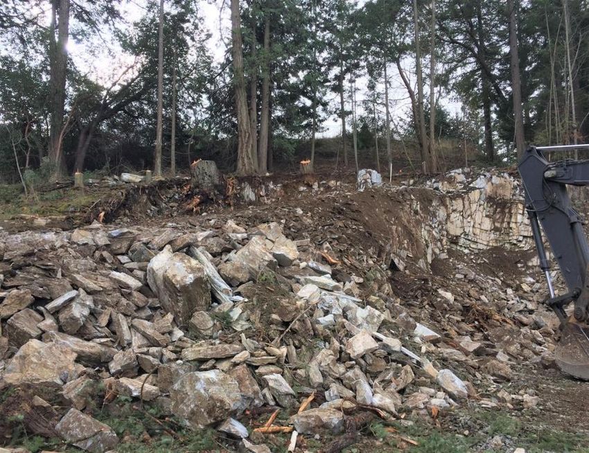
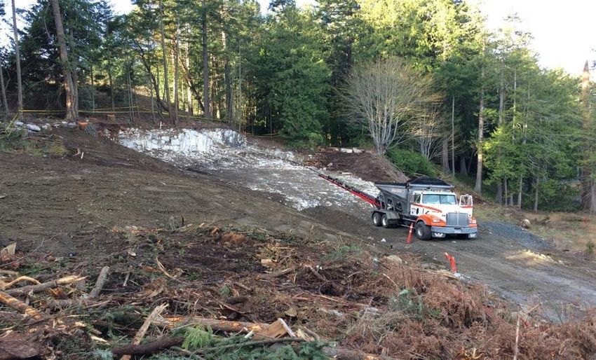
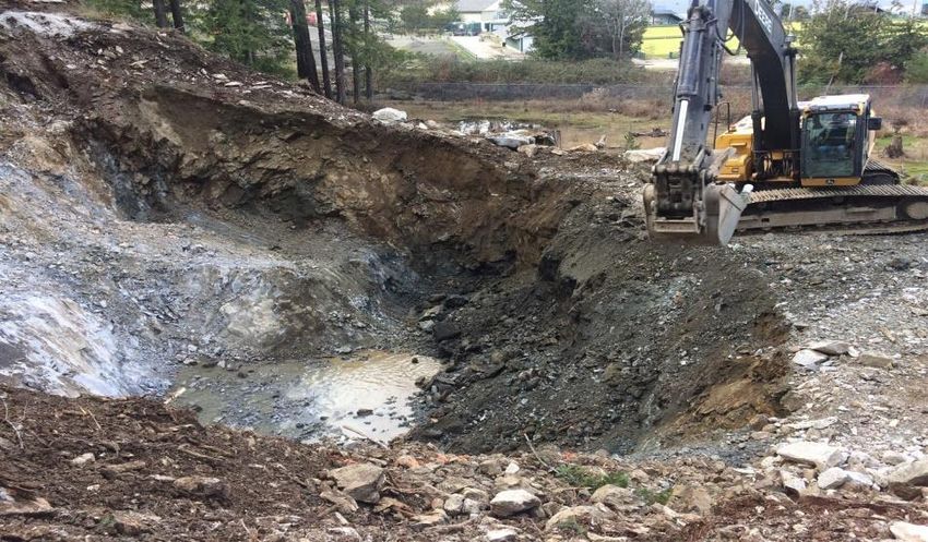
Remediation

Approximately 2,600 m3 of contaminated rock and overburden
was removed through blasting and excavation
Remediation

Blast mats installed prior to blasting rock   Mechanical excavation used in tricky areas

       Final excavation footprint             Clean backfilled excavation floor
Remediation Contaminated waste rock stockpiled on liner Stockpiled soil prior to disposal Placement of topsoil over backfilled excavation Final layer of hydroseeding
Summary
Shallow depth and localized nature of bedrock contamination
was ideal for remediation via excavation and disposal

Clean excavation margins confirmed the contamination source
was localized, likely associated with historic asphalt operation

Structural geological interpretation of contaminated fractures
provided a defensible strategy and optimal delineation targets
at relatively low cost
QUESTIONS?
ITRC Disclaimers:

This material was prepared as an account of work sponsored by an agency of the United States Government. Neither the United States Government nor any
agency thereof, nor any of their employees, makes any warranty, express or implied, or assumes any legal liability or responsibility for the accuracy,
completeness, or usefulness of any information, apparatus, product, or process disclosed, or represents that its use would not infringe privately owned rights.
Reference herein to any specific commercial product, process, or service by trade name, trademark, manufacturer, or otherwise does not necessarily constitute
or imply its endorsement, recommendation, or favoring by the United States Government or any agency thereof. The views and opinions of authors expressed
herein do not necessarily state or reflect those of the United States Government or any agency thereof and no official endorsement should be inferred.

The information provided in documents, training curricula, and other print or electronic materials created by the Interstate Technology and Regulatory Council
(“ITRC” and such materials are referred to as “ITRC Materials”) is intended as a general reference to help regulators and others develop a consistent approach
to their evaluation, regulatory approval, and deployment of environmental technologies. The information in ITRC Materials was formulated to be reliable and
accurate. However, the information is provided "as is" and use of this information is at the users’ own risk.

ITRC Materials do not necessarily address all applicable health and safety risks and precautions with respect to particular materials, conditions, or procedures in
specific applications of any technology. Consequently, ITRC recommends consulting applicable standards, laws, regulations, suppliers of materials, and
material safety data sheets for information concerning safety and health risks and precautions and compliance with then-applicable laws and regulations. ITRC,
ERIS and ECOS shall not be liable in the event of any conflict between information in ITRC Materials and such laws, regulations, and/or other ordinances. The
content in ITRC Materials may be revised or withdrawn at any time without prior notice.

ITRC, ERIS, and ECOS make no representations or warranties, express or implied, with respect to information in ITRC Materials and specifically disclaim all
warranties to the fullest extent permitted by law (including, but not limited to, merchantability or fitness for a particular purpose). ITRC, ERIS, and ECOS will not
accept liability for damages of any kind that result from acting upon or using this information.

ITRC, ERIS, and ECOS do not endorse or recommend the use of specific technology or technology provider through ITRC Materials. Reference to technologies,
products, or services offered by other parties does not constitute a guarantee by ITRC, ERIS, and ECOS of the quality or value of those technologies, products,
or services. Information in ITRC Materials is for general reference only; it should not be construed as definitive guidance for any specific site and is not a
substitute for consultation with qualified professional advisors.

SABCS Disclaimer:

While representing science available to the greatest extent possible, these documents may or may not be used in whole or in part by government including BC
or federal agencies. The materials are an expression of scientific opinion. Use of the material herein is at the sole discretion and responsibility of any reader
and the SABCS assumes no liability express or implied for its use. While available for information in your practice, note that the reports are the property of the
SABCS and cannot be reproduced or disseminated for commercial educational purposes or to create guidance products without the express written
permission of the SABCS.
You can also read