Battery Storage IMIA Working Group Paper 112 (19) - OCTOBER 2019 - IMIA, the International Association of ...
←
→
Page content transcription
If your browser does not render page correctly, please read the page content below

Battery Storage
IMIA Working Group Paper
112 (19)

OCTOBER 2019

IMIA CONFERENCE

                           1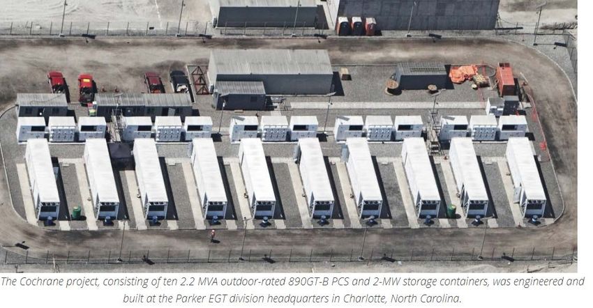
Battery Storage                     IMIA Working Group Paper 112 (19)

            Working Group Members
                          Chairman
                          Patrice Nigon
                  (Swiss Re Corporate Solutions)

                        Contributors
                          Andrew Norris
                  (Swiss Re Corporate Solutions)
                       Cesare Borgia, PhD
                   (Zurich Insurance Company)
                       Christofer Lindholm
                  (Swiss Re Corporate Solutions)
                         Hector Raymond
                            (Munich Re)
                               K.H.Ho
                               (Scor)
                           Kunal Geriya
                   (Zurich Insurance Company)
                          Mamoon Alyah
                              (Ceerisk)
                          Neil Andrews
                             (Helvetia)
                         Timo Linneweh
                            (HDI Global)
                          YoungJun Lee
                               (QBE)

                     IMIA EC Sponsor
                          Guido Benz
                  (Swiss Re Corporate Solutions)

                                                                   2
Battery Storage                           IMIA Working Group Paper 112 (19)

                  Executive Summary
As the use of renewable energy sources increase, so does the need to both
stabilize the grid, due to the inherent intermittency of the generated power,
but also to provide means for storing the energy to use during peak demands
or when the renewable sources aren't available.

A more thorough explanation on the importance of battery storage and the
expected market situation is discussed in the beginning of this paper.

Battery Energy Storage Systems (BESS) play an important role in the
renewable energy transition. However, these systems are considered
relatively new technology and could in many ways be seen as prototypical.
As with most developing technologies there are often some challenges to
tackle before the technology can be seen as proven. As the technology is
developing fast, this paper is intended to provide an overview of the current
technologies and what their differences are.

The significant amount of energy stored in these systems could result in
danger or loss if some of the challenges aren’t managed in a correct way.
This paper presents the main loss exposures and types of causations of fire
loss as well as actual market loss examples.

The theory for BESS technology is explained, as well as what could go wrong
and how errors can be prevented. The main standards and codes that should
be applied when certifying the batteries and how to get more in depth
information on loss prevention are also presented in the paper.

There are several considerations for the underwriter to make before insuring
BESS's. Some of the main considerations to make are provided, as well as
the reasoning behind. A check-list for battery projects is also provided.

The vocabulary and definitions associated with battery storage can be found
in the appendix section where also the different battery types are explained
in more detail.

The aim of this paper is to provide the reader with enough information to
make informed decisions when it comes to insuring battery storage systems.

                                                                           3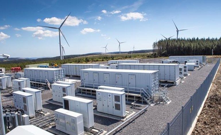
Battery Storage                                                                    IMIA Working Group Paper 112 (19)

Content

1.    INTRODUCTION ..................................................................................................................................... 5

2.    IMPORTANCE OF BATTERY STORAGE..................................................................................................... 6

3.    USAGE/PURPOSE OF BATTERY STORAGE ............................................................................................. 11

4.    THE MAIN TYPES OF BATTERY TECHNOLOGIES USED FOR ENERGY STORAGE ...................................... 17

5.    UNDERWRITING: MATERIAL DAMAGE ................................................................................................. 21

6.    UNDERWRITING: THIRD PARTY LIABILITY ............................................................................................ 40

7.    UNDERWRITING: DSU AND BI .............................................................................................................. 42

8.    UNDERWRITING: CHECK LISTS AND CLAUSES....................................................................................... 47

9.    LOSSES AND REPAIRS........................................................................................................................... 52

10.   CONCLUSION ....................................................................................................................................... 61

11.   APPENDIX 1: BATTERY BASIC VOCABULARY AND DEFINITIONS ........................................................... 62

12.   APPENDIX 2: BATTERY TYPES: ADDITIONAL INFORMATION................................................................. 64

13.   APPENDIX 3 : INVESTIGATION RESULT ON ESS FIRE ACCIDENT KOREA MINISTRY OF TRADE INDUSTRY
      ENERGY JUNE 19. ................................................................................................................................. 71

14.   LINKS AND BIBLIOGRAPHY................................................................................................................... 76

                                                                                                                                                        4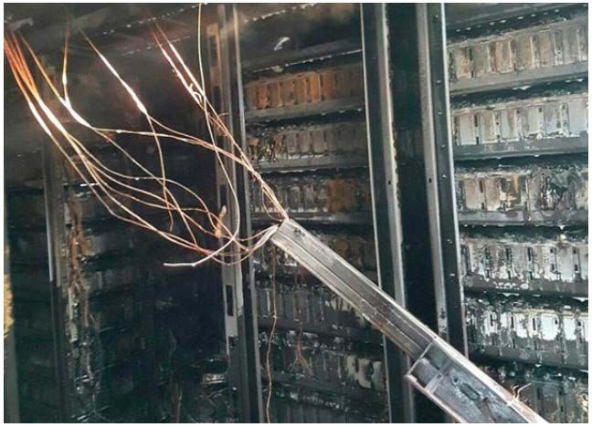
Battery Storage                                 IMIA Working Group Paper 112 (19)

    1.      Introduction

On 24 April 2019, the small German city of Bordesholm celebrated setting a 10 MW
Battery Electrical Storage System (BESS) in service. This investment, coupled with a
Bio Gas Plan, provides electricity to the 7,500 people inhabiting the community which
has the target to meet 100% of its demand with renewable energy sources by 2020.
The primary role of this BESS is to help stabilize the regional network (frequency
containment reserve), and to provide back-up power. In case of a grid outage, it can
help putting back the grid in operation (Black Start) and enable the operation of an
independent local grid (Islanding). This investment saves 12,000 tons of CO2 per year.
For its contribution to the grid stability the municipality receives a remuneration from
Tennet, one of the four grid owners.

Every week, new battery system developments are announced. They're either
connected to solar plants, wind farms (onshore or offshore), or used as a regulating
system to improve the stability of the electrical networks.

The combination of the falling price of Li-Ion batteries (-85% during the last 9 years)
and the emergence of renewable energy lead Bloomberg to estimate that the global
energy storage market* will grow to a cumulative 942GW / 2,857GWh by 2040,
attracting $620 billion in investment over the next 22 years (as from 2018).

* Bloomberg NEF Blog 6/11/2018

                                                                                      5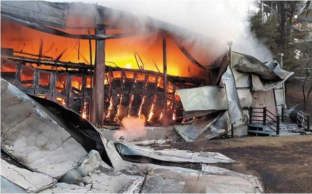
Battery Storage                                 IMIA Working Group Paper 112 (19)

This does not consider the emergence of the 10-times-bigger storage capacity
expected for electrical vehicles (EV). Tens of billions of USD are invested in the R&D
for these EVs in the context of a "patent war", with China owning 83% of the patent
rights, followed by Japan and South Korea.
But the emergence of these new technologies is also linked to new exposures. What
are the new risks? What can trigger a fire in a battery? How does the charging mode
influence the life potential of a battery? What are the current technologies, and are
some safer than others? When indemnifying a claim, should we consider the lifetime
of the battery. What are the revenue components to consider when assessing the DSU
or BI exposure of a plant? These are the questions that we try to answer in the following
chapters.

    2.      Importance of Battery Storage

Energy storage sources allow the management of power supplies that customers
require when they need them the most. Developing technology to store electrical
energy to meet power demands whenever it’s needed will represent a breakthrough in
peak load electricity distribution. Energy storage decouples supply and demand and
introduces an unprecedented level of flexibility and control. Installed systems can
complement intermittent sources of renewable energy such as wind, solar, wave and
tidal in an attempt to balance energy production and consumption.

                         Forms of Energy Storage
   Mechanical              Thermal               Electrical        Electrochemical
                                                                    Battery Energy
   Hydropower            Sensible heat       Super-capacitors
                                                                       Storage
 Pumped storage           Latent heat
 Compressed air
Flywheel Energy
  Gravitational
    Potential

Energy comes in multiple forms including, electrical chemical, mechanical, electrical
and kinetic to name a few. Many types of technologies can store this energy, including
electrical, thermal, mechanical, and electrochemical technologies. Hydroelectric
pumped storage, a form of mechanical energy storage, accounts for the greatest share

                                                                                       6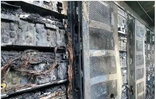
Battery Storage                                 IMIA Working Group Paper 112 (19)

of large-scale energy storage power capacity in the United States. Other examples of
these systems are flywheels, compressed air storage, super capacitors and battery
energy storage systems (BESS). Anyone following electric utility trends knows that
BESS tops the list of exciting and transformative technologies in the power industry
today.

                                                              Source: https://www.eia.gov/

As the market share of renewables in power production increases, so does its
intermittency. This leads to an increased need for flexible power providers on the
electricity grid. Battery Energy Storage has a substantial technical advantage over
conventional generation units in terms of load shifting capacities thanks to their fast
ramping rate, which makes these systems a dominant choice. Batteries have unique
abilities to both charge and discharge from the grid and ramp up and down at speeds
that traditional generators can’t match.

A BESS needs to suit a customer’s electricity demand profile. Customer installations
connected to network operator distribution systems are designed to export power into
the grid, while remote area supplies are not. BESS in remote installations may have to
be integrated with wind and / or diesel generators as well as solar PV panels. BESS
prices are projected to continue a downward trend and future storage is now being
seriously looked at for several different applications.

The important distinction for battery storage is the different ratings between power and
energy capacity. Conventional generation technologies are often characterized in
terms of power capacity, which is the maximum instantaneous amount of power output,
and is measured in units such as megawatts (MW). However, batteries are limited by
the time they can sustain power output before they need to recharge. The duration i.e.
the length of time that a storage system can sustain power output at its maximum
                                                                                             7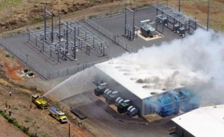
Battery Storage                                  IMIA Working Group Paper 112 (19)

discharge rate, typically expressed in hours. The energy capacity of the battery storage
system is the total amount of energy that can be stored or discharged by the battery
storage system and is measured in units such as megawatt hours (MWh). A “large
scale” BESS system would be defined as a single installation >1MW capacity. Small-
scale refers to systems that are less than 1 MW in power capacity and are typically
connected to a distribution network.

A range of battery technologies are available, the most common being lithium-ion, lead
acid, nickel-based, flow technologies and hybrid-ion technology. Different battery
technologies and chemistries have different performance capabilities and different
requirements for installation, operation and maintenance. Various battery types will
have different probabilities of failure and varying consequences of that failure (i.e. a
different risk profile). Those responsible for the specification and / or supply of the
BESS must ensure that an appropriate risk assessment is undertaken for the specific
customer circumstances, location, the equipment proposed and its installation.

Researchers at Bloomberg NEF (BNEF) predict that utility scale lithium-ion battery
storage systems will transform the economic case for batteries in both the vehicle and
the power sector. The battery boom has penetrated the Chinese market, US-California
and will follow everywhere else. Projections for new installations have already been
exceeded in some countries. The analysts at Bloomberg NEF predict that the global
energy-storage market could reach a cumulative 942 gigawatts by 2040 and that this
boom will be fueled by sharply falling battery costs. BNEF sees the capital cost of a
utility-scale lithium-ion storage system falling another 52 percent by 2030.
Governmental stimulus is likely to play a part in this. For example, South Korea took
the top spot in 2018 with nearly 1.1 gigawatt-hours of energy storage deployed,
compared to just under 700 megawatt-hours in the U.S. This was primarily the result
of the Korean government’s policy to allow storage-backed wind and solar projects to
earn renewable energy certificates worth five times their capacity value, which drove
nearly $400 million in energy storage investments and a pipeline of projects that had
overshot a goal of 800 megawatt-hours by 2020. However, BESS costs are still fairly
high and there is a lack of regulatory requirements and subsidies are not universally
available. BESS’s still may not be cost-effective for any one application in any given
region. Government policy uncertainties may restrain larger-scale battery installations,
yet are imperative to direct grid operators to create mechanisms to accommodate
supply bottlenecks and maintain grid stability.

Between 2003 and 2017, 734 MW of large-scale battery storage power capacity was
installed in the United States, two-thirds of which was installed in the past three years.
As of December 2017, project developers report to EIA that 239 MW of large-scale
battery storage is expected to become operational in the United States between 2018
and 2021.

                                                                                        8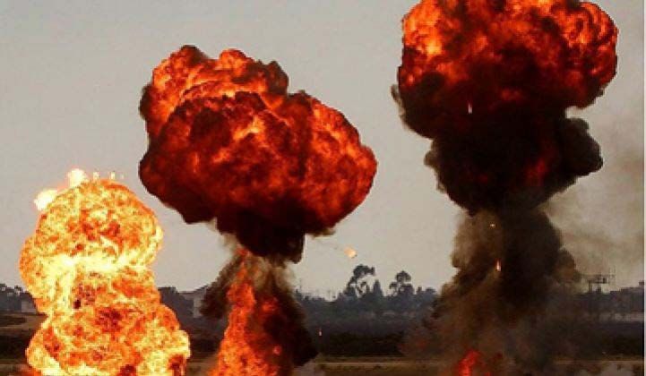
Battery Storage                                          IMIA Working Group Paper 112 (19)

         U.S. Large-Scale BESS Installations by Region (2017)

                          Source: U.S. Energy Information Administration | US. Battery Storage Market
                                                                                               Trends

The next few years will continue to define the future market leaders in the BESS
industry. The increased competition in this space is the key driver that is making
storage more and more attractive to utilities and related companies. Energy storage
installations result in a reduction in peak electrical system demand and system owners
are often compensated through regional grid market programs. An increase in owner
participation may be stimulated by regulator offered incentives. State policy, wholesale
market rules, and retail rates will play a central role in where opportunities for battery
storage exist. Installed capacity is expected to grow as costs decline and market rules
are updated.

The costs for battery storage technologies depend on technical characteristics, such
as the power and energy capacity of a system. Costs will be driven by technological
and site-specific requirements and can be divided into three main categories, based
on the nameplate duration of the battery storage system, which is the ratio of
nameplate energy capacity to nameplate power capacity. Short-duration battery
storage systems refer to systems with less than 0.5 hours of nameplate duration. The
medium-duration battery storage category includes systems with nameplate durations
ranging between 0.5 hours and 2.0 hours, while the long-duration category includes all
systems with more than 2.0 hours of nameplate duration.

                                                                                                        9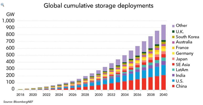
Battery Storage                               IMIA Working Group Paper 112 (19)

According to Clair Addison, AES Stakeholder Manager: “In the eight years that AES
has been operating in the BESS sector, lithium-ion battery costs have fallen by 80%.
Renewable energy penetration and peak demand combined with aging thermal plants,
could see a peak demand of 16GW by the mid-2020s and BESS [facilities] could
provide 50% of that.”

Total Installed Cost of Large-Scale Battery Storage Systems by
Duration

The large-scale energy storage capacity additions in the US since 2003 have been
almost exclusively electrochemical battery energy storage systems. For this reason,
this paper will focus on these storage technologies.

                                                                                 10
Battery Storage IMIA Working Group Paper 112 (19)
3. Usage / Purpose of Battery Storage
Among energy-intensive economies of the world, there is a shift occurring, from
centralized, fossil-fueled power generation systems to more distributed and inherently
variable renewable energy sources. In addition to this, the nature of electrical load is
changing, such as that due to large-scale data centres, increased use of air-
conditioning systems and the deployment of electric vehicle (EV) charging
infrastructure. Changes in the architecture and controllability of the grid call for smart,
efficient power transmission and distribution networks. BESS technology will not only
facilitate the integration of more renewable energy but also, help create a smarter and
more reliable grid. Revenue from spinning reserve (meaning ramping over a specified
range within 10 minutes and running for at least two hours) as well as reactive and
active power management of the grid are also revenue avenues. The challenge in
adding battery storage to a grid run by generators serving load is that it doesn’t work
quite like those resources. Electrical storage systems that charge and discharge actual
electrons, can go in both directions, and react much more quickly than many other
resources. But it’s also limited in duration, and of course is only as efficient or as clean
as the electricity it stores, or the balance between its charging and discharging cycles
over its lifespan.
The first large scale (i.e. commercial) peak-shaving system (2 MW / 4 MWh) was
deployed by Chevron Energy Solutions. AES Energy Storage LLC has deployed more
than 50 MW of systems as an independent power producer (IPP) for frequency
regulation and spinning reserve services. Other utilities are also deploying megawatt-
scale units for PV integration and distribution grid support.
In many locations the regulatory status and rules to operate a BESS are not fully
defined. In the USA, The Federal Energy Regulatory Commission (FERC) issued its
landmark Order 841 on February 15, 2018, in which it directed regional grid operators
to remove barriers to the participation of electric storage in wholesale markets. By
directing the regional grid operators to establish rules that open capacity, energy, and
ancillary services markets to energy storage, the Order affirmed that storage resources
must be compensated for all these services. Furthermore, Order 841 created a clear
legal framework for storage resources to operate in all wholesale electric markets and
expanded the universe of solutions that can now compete to meet electric system
needs.
11Battery Storage IMIA Working Group Paper 112 (19)
Battery Energy Storage Applications
Type Duration
Frequency Regulation .5 to 1 h
Critical Power up to 1 h
Generation Enhancement up to 1 h
Renewable Integration up to 4 h
T&D Enhancement up to 4 h
Energy Cost Control up to 4 h
Micro grids & Islands up to 4 h
Capacity Peak Power up to 6 h
Source:
Overview of the Energy Storage Market and Fluence, an AES and Siemens Joint Venture September 6, 2018
Batteries have physical and operational constraints such as power output and
discharge duration. These constraints are often designed with the intent of optimizing
the delivery of certain types of services or applications to the grid. It is also possible
and sometimes necessary to combine applications to maximize the value of the
system.
Purpose Descriptions
Some uses for BES systems and their definitions include:
Frequency regulation (ancillary services) – this helps balance momentary
differences between demand and supply, often in response to deviations in the
interconnection frequency from base frequency. Regulation involves managing
interchange flows with other control areas to match closely the scheduled
interchange flows and momentary variations in demand within the control area.
The primary reasons for including regulation in the power system are to maintain
the grid frequency and to comply with grid regulations such as the North
American Electric Reliability Council’s (NERC’s) standards.
Spinning reserve (SR) – generation capacity that is online but unloaded and that
can respond within 10 minutes to compensate for generation or transmission
outages. SR provides synchronized capacity for grid frequency management,
which may be available to use during a significant frequency disturbance. This
reserve ensures system operation and availability. Importantly for storage,
12Battery Storage IMIA Working Group Paper 112 (19)
generation resources used as reserve capacity must be online and operational
(i.e. at part load). Unlike generation, in almost all circumstances, storage used
for reserve capacity does not discharge at all; it just has to be ready and
available to discharge if needed.
Voltage or reactive power support – this ensures the quality of power delivered
by maintaining the local voltage within specified limits by serving as a source or
sink of reactive power. To manage reactance at the grid level, system operators
need voltage support resources to offset reactive effects so that the
transmission system can be operated in a stable manner.
Load following – the system supplies (discharges) or absorbs (charges) power
- also known as a form of ramp rate control. Load following is characterized by
power output that generally changes as frequently as every several minutes.
The output changes in response to the changing balance between electric
supply and load within a specific region or area. Most renewable applications
with a need for storage will specify a maximum expected up- and down-ramp
rate in MW /minute and the time duration of the ramp.
System peak shaving – reduces or defers the need to build new central station
generation capacity or purchase capacity in the wholesale electricity market,
often in times of high (peak) demand. Depending on the circumstances in a
given electric supply system, energy storage could be used to defer and / or to
reduce the need to buy new central station generation capacity and / or
purchasing capacity in the wholesale electricity marketplace. The marketplace
for electric supply capacity is evolving. In some cases, generation capacity cost
is included in wholesale energy prices (as an allocated cost per unit of energy).
In other cases, market mechanisms may allow for capacity-related payments.
Load management – provides a customer-related service, such as power
quality, power reliability (grid-connected or micro-grid operation), retail electrical
energy time-shift, demand charge management, or renewable power
consumption maximization.
Storing – excess wind and solar generation reduces the rate of change of the
power output from non-dispatchable generators, like wind or solar, in order to
comply with local grid codes for grid stability or prevent over production, which
might incur penalties. High solar adoption will create a challenge for utilities to
balance supply and demand on the grid. This is due to the increased need for
electricity generators to quickly ramp up energy production when the sun sets
and the contribution from PV falls. In 2013, the California electric grid operators
(CAISO) published a graph nicknamed “The Duck Curve” that is now
commonplace in conversations about large scale deployment of solar (PV)
power. It shows the state’s demand for electricity over a single day, subtracting
out the state’s growing supply of solar and wind power. The Duck Curve is a 24-
hour period snapshot that illustrates where high solar adoption creates a
challenge for utilities to balance supply and demand on the grid.
13Battery Storage IMIA Working Group Paper 112 (19)
Solar capacity has reduced fossil fuel generation load during daylight hours.
During the evening hours when residents return home from work, the state’s
aging natural gas plants then increasingly struggle to ramp up to meet the
evening (6pm-8pm) demand.
Solar power coupled with BESS technologies could alleviate, and possibly
eliminate, the risk of over-generation. Solar curtailment isn’t necessary when
excess energy can be stored for use during peak electricity demand. In short,
battery storage could make it easier for utilities to rely on solar energy to meet
customer needs around the clock and eliminate the “ramp up” from fossil fuel
generation during evening hours, when solar power is low. According to the
Energy Information Administration (EIA), the installed amount of PV is expected
to triple by 2030—potentially migrating the duck curve outside of California.
Electric energy time (Arbitrage) – involves purchasing inexpensive electric
energy, available during periods when prices or system marginal costs are low,
to charge the storage system so that the stored energy can be used or sold at
a later time when the price or costs are high. Alternatively, storage can provide
similar time-shift duty by storing excess energy production, which would
otherwise be curtailed, from renewable sources.
Black Start – storage systems provide an active reserve of power and energy
within the grid and can be used to energize transmission and distribution lines
and provide station power to bring power plants online after a catastrophic
failure of the grid.
14Battery Storage IMIA Working Group Paper 112 (19)
Transmission and distribution deferral – keeps the loading of the transmission
or distribution system equipment lower than a specified maximum. This allows
for delays or completely avoids the need to upgrade a transmission system or
avoids congestion-related costs and charges.
Co-located generator firming – provides constant output power over a certain
period of time of a combined generator and energy storage system. For
example, BES systems have found useful application in smoothing wind power
output. Batteries are charged when wind turbines are operating but then provide
supplemental power when the turbines are idle.
Noteworthy BESS Storage Project Uses
Puerto Rico Electric Power Authority (PREPA)
Grid Services: Frequency control and spinning reserve
Project Location: Sabana Llana substation, San Juan, Puerto Rico
Commissioned: 1994
Power/Energy: 20 MW/14 MWh
Battery Type: Lead-acid, flooded cell, by C&D Battery
The PREPA BESS also provides frequency regulation and spinning reserve services
to the island grid of Puerto Rico. This battery system demonstrated that the faster
response of a battery system could be an invaluable resource for grid stability, superior
to CTs for frequency regulation and spinning reserve duty. However, operational
issues that surfaced soon after the battery was commissioned showed that frequency
regulation duty requires far more cycling of the battery than originally estimated in the
design and engineering phase of the project. The battery was decommissioned in
1999.
Southern California Edison
Grid Services: Demonstrate load-levelling, transmission line stability, T&D deferral,
local VAR control, and local area black start
Project Location: Chino, CA
Commissioned: 1988
Power/Energy: 10 MW/40 MWh
Battery Type: Lead-acid, flooded cell, by Exide
The Chino project was an early demonstration of a large battery for multiple
applications in the U.S. grid. The project was jointly sponsored by EPRI, DOE, and the
International Lead Zinc Research Organization (ILZRO), supported by SCE as the host
utility. This landmark project provided valuable experience with maintaining large
15Battery Storage IMIA Working Group Paper 112 (19)
banks of flooded lead-acid batteries and high-voltage battery strings. The lessons
learned in this project influenced later battery projects and also spurred the
development of smaller modular storage systems versus large field-assembled battery
systems. The Chino project was also the largest utility battery system in the world until
the PREPA BESS and later the Fairbanks battery projects were commissioned in 1994
and 2003, respectively. The Chino battery was decommissioned in 1997.
Golden Valley Electric Association (GVEA)
Application: VAR Support, spinning reserve, power system stabilization
Project Location: Fairbanks, AK
Commissioned: 2003
Power/Energy: 27 MW/14.6 MWh
Battery Type: Nickel/cadmium, by SAFT
NOTE: At the time of writing this paper, the Fairbanks battery storage system is the
largest in the United States and the only one using NiCd batteries. It also provides a
real-world example of the successful stacking of several grid services, including
voltage support, spinning reserve, and reserve power for Fairbanks in the event of an
outage on the transmission line connecting Fairbanks to Anchorage.
Batwind (Hywind Scotland floating offshore wind farm)
Application: the world’s first BESS for a floating wind farm
Project location: Peterhead, Scotland
Capacity: 1MW
Commissioned: 2018
Electricity produced at the world’s first floating offshore wind farm, Hywind Scotland,
located 25 kilometres off the coast of Peterhead, will be transported via cables to an
onshore substation where the 1 MW batteries are placed and connected to the grid.
16Battery Storage IMIA Working Group Paper 112 (19)
4. The main types of battery technologies used
for energy storage
4.1 Storage battery technology
Various technologies can be harnessed for battery energy storage, but these come
certain advantages and disadvantages. Currently most of the battery energy storage
systems that are installed use Lithium-ion technology followed by lead-acid, sodium
salt and flow batteries.
Specification Lead- Nickel Lithium- Flow Sodium-
acid based ion sulfur (NaS)
Specific
energy 30 – 50 up to 120 up to 250 up to 150 up to 150
[Wh/kg]
Life cycles up to up to up to up to
200 – 300
[80% DoD] 500 10.000 1.000 4.000
Has to be
Thermally Thermally heated
Protection
Safety stable, stable, Thermally possibility of
circuit
requirements can emit fuse stable short circuits
mandatory
H2 protection when cooling
down
Cost Low Moderate high high high
Self-discharge
5% 20 – 30% 5 – 10%
[per month]
Source: Swiss RE BESS leaflet
17Battery Storage IMIA Working Group Paper 112 (19)
4.2 Lead-acid batteries
Lead-acid batteries, are the oldest type of rechargeable battery systems, are relatively
rugged and forgiving if abused, and can be economically priced. However, they have
low specific energy, making them bulky, and limited cycle count compared to other
types. In general they have a depth of discharge of approx. 60%, meaning that 40%
of their capacity cannot be used if the cell should not be damaged for the rest of their
lifetime.
Lead-acid systems perform best around 20°C and operation above this temperature
will result in reduction of lifetime and capacity. These batteries are thermally stable
and do not need any internal safety measures, but they can emit hydrogen gas so the
storage area should be well ventilated to prevent the emergence of an explosive
atmosphere.
Lead-acid batteries are most often used as uninterruptible power supplies (UPS).
4.3 Nickel-based batteries
Mature and well understood nickel-based batteries are used where long service life,
high discharge current and extreme temperature tolerance are required. Nickel
Cadmium “NiCd” batteries in particular are one of the most rugged and enduring
battery types and are the only ones with a chemistry that allows ultra-fast charging
with minimal stress.
18Battery Storage IMIA Working Group Paper 112 (19)
Nickel based batteries are mainly used in medical devices, power tools and industrial
application (like UPS). The main types are:
Nickel Cadmium (NiCd)
Nickel-metal-hydride (NiMH)
Nickel-iron (NiFe)
Nickel-zinc (NiZn)
Nickel-hydrogen (NiH)
4.4 Lithium-ion (Li-ion) batteries
Li-ion battery technology is replacing many applications that were previously served
by lead-acid and nickel-based batteries. They do not suffer significantly from the
memory effect, unlike their NiMH and NiCd counterparts. Due to safety concerns they
require special handling and protection circuits. Li-ion batteries are more expensive
than most other batteries, but high cycle count and low maintenance reduce the cost
per cycle over many other chemistries.
This type of battery is mainly used for portable appliance, automotive (e-mobility) and
also large-scale battery storage.
Several types of Li-ion batteries exist:
Lithium Cobalt Oxide (LiCoO2)
Lithium Manganese Oxide (LiMnO2)
Lithium Manganese Oxide (LiMnO2)
Lithium Iron Phosphate (LFP - LiFePO4)
Lithium Nickel Cobalt Aluminum Oxide (LiNiCoAlO2, NCA)
Lithium Titanate
One of the most catastrophic failures of a lithium-ion battery system is a cascading
thermal runaway event, where multiple cells in a battery fail due to a failure starting at
one individual cell. Thermal runaway can occur due to exposure to excessive
temperatures, external short circuits due to faulty wiring, or internal shorts due to cell
defects. Thermal runaway events result in the venting of toxic and highly flammable
gases and the release of significant energy in the form of heat. If ignited, these gases
can cause enclosed areas to over-pressurize, and if unmitigated, this over-pressure
can result in an explosion and severe damage to the battery and surrounding
equipment or people. An explosion scenario can be even more severe for a large
battery pack, where the heat generated by one failed cell can heat up neighbouring
cells and lead to a thermal cascade throughout the battery pack.
19Battery Storage IMIA Working Group Paper 112 (19)
Source:
Thermal Runaway and Safety of Large Lithium-Ion Battery Systems; Nicolas Ponchaut
4.5 Flow batteries
Flow batteries are accumulators that store electrical energy in two chemical liquid
components. A typical element for a flow battery is currently vanadium. The voltage is
generated on a membrane (similar to traditional fuel cells). The liquids are stored in
two separate tanks and pumped into the membrane. The size of the membrane
determines the power (kW) of the battery, while the size of the tanks determines the
capacity (kWh) of the battery. This makes this kind of battery easily scalable by
increasing the size of the tanks.
Due to its size and high possible capacity, this technology is well suited for large scale
energy storage.
Advantages Energy and power can be scaled independently.
No “thermal runaway” unlike traditional lithium cells.
Disadvantages Still under development
Size of the battery (tanks)
Complex system of pumps, sensors and vessels are required
for operation
20Battery Storage IMIA Working Group Paper 112 (19)
5. Underwriting: Material Damage
The scope of this section is to provide the reader with an overview of the main causes
of material damage (physical loss) in a BESS, with a special focus on insurance related
matters.
The driving force in a catastrophic failure of a BESS (as in all energy storage systems)
resides in the technical need to retain the highest amount of energy in the smallest
possible volume, using physical and chemical properties of materials, maintaining at
the same time the ability to upload and recall power/energy from the storage system
at a rate which is optimal for the kind of load fed by the device.
In the specific case of BESS, the feature of energy storage is achieved by means of
electrochemical reactions taking place in the so called “cell”, that is the smallest
modular element of the storage system.
Cells are organized in larger modules that can be in turn connected to optimize the
specific operative conditions for which the whole BESS device is designed. Almost as
important as the electrochemical elements where energy is finally stored, the
balancing, equalizing and control electronics give a fundamental contribution not only
to the operational efficiency, but also to the safety and resilience of the whole device
to defects or to unexpected external stresses [1,2,3,4]
21Battery Storage IMIA Working Group Paper 112 (19)
The exposure to physical losses (electromechanical, electrochemical, fire, explosion)
and the failure modes of BESS strongly depend on the BESS technology, not only at
the level of the single cell, but including all the technical setup of the device: circuit
topology, balancing, equalization and control electronics,
environmental/temperature/ventilation control, etc. Guidelines exist to assist the
design, installation and operation of BESS within acceptable safety limits [5].
Due to the extremely high concentration of energy, oxygen and combustibles present
in a cell when charged, in case of off-spec conditions or stresses, an unfavorable
combination of effects may lead to a self-amplifying reaction loop, leading to
catastrophic damage (fire, explosion), called Thermal Runaway.
22Battery Storage IMIA Working Group Paper 112 (19)
Although thermal runaway is observed and theoretically possible in almost all currently
available cell technologies [6], it is a priority concern for Li-ion based technologies.
A typical example of a thermal runaway event may start with a point source of heat
inside of or attached to a single cell, for example an internal short circuit or a hot object
in contact with the cell, leading to the damaging of cathode/anode separator, producing
a fast discharge of energy and therefore more heating, causing electrolyte degradation
and formation and release of flammable/explosive gases, producing flames or
explosions and so forth a self-sustaining loop of reaction/energy release.
Given the very high number of parameters involved, it is impossible to establish “a-
priori” if a combination of inputs/events will produce for sure a catastrophic event [7-9].
Some authors have tried to propose methodologies to study “a-posteriori” thermal
runaway accidents by breaking them down to a series of partial reactions/events [7,8],
but it is evident that lab-based tests with simplified set-ups can only provide hints and
very broad guidelines to help understanding triggers and aggravating factors for this
kind of catastrophic failure.
23Battery Storage IMIA Working Group Paper 112 (19)
A very partial list of parameters that may trigger and drive a thermal runaway event
include:
Cell technology and materials, electrolytes, overcharge, external heat, cell geometry,
circuit topology, mechanical stress /deformation, gas emission, nature of the emitted
gases, ventilation of the installation, etc.
24Battery Storage IMIA Working Group Paper 112 (19)
In their papers / proceedings [8, 9] Döring, Wörz and Scharner, give a number of
examples of possible thermal runaway initiation triggers, including: overcharge, crush,
thermal exposition, high current/voltage exposition, external short circuit, internal short
circuit (e.g. nail penetration, particle inclusion).
All these triggers simulate the real-world occurrence of material / design /
manufacturing defects, accidents, mechanical impacts (e.g crushing / bending /
piercing), wrong operation (short circuit, wrong charging) or exposure to off-spec
temperature. Again, although they reach the conclusion that no general statement or
model can be reached, they provide an empirical estimate for the likelihood that certain
thermal, mechanical and electrical off-spec stresses may or may not trigger a thermal
runaway. Several research works were carried out to understand the contribution to
25Battery Storage IMIA Working Group Paper 112 (19)
the thermal runaway phenomenon by the various constructive or technological
elements of BESS: anode, cathode, separator, electrolytes, casing, etc. These works
show a large variability in thermodynamics and kinetics for reaction’ required
conditions, energy release rates, temperature evolution and propagation/extinguishing
times for gaseous and solid components involved or released during the event. [9, 10]
It is interesting to note that if the interpretation of single triggers proves to be difficult,
the combination or concatenation of their effects (real world case) is extremely
challenging to comprehend, to model and to control with guidelines or with protection
measures or devices.
Although catastrophic events are for sure a topic of great concern for both the industry
and the insurance sectors, the topic of the evaluation of residual life of BESS is also
extremely interesting and potentially of very high impact for what concerns economic
aspects, especially after an insured loss.
As a matter of fact, due to their typically long payback period, it is of fundamental
importance to estimate the residual life of a BESS after an event damaging or
obliterating part or all of the storage system. A fair quantification of the financial loss
due to the physical loss of an asset of this kind cannot leave aside the consideration
that these systems have an intrinsic but difficult to assess rate of performance decay,
connected with their operational pattern, maintenance and environmental conditions.
[11, 12]
It may not be of secondary importance, for insurance matters, to consider the possibility
of cyber-attacks aimed at sabotaging the complex control logic that manages the
correct operation of a BESS. Malicious software could be designed and installed to
produce a range of damages, from less easily visible (but economically costly)
accelerated decay of performance or health of the whole storage system to a more
spectacular thermal runaway event.
Finally, it is worth to mentioning that catastrophic events like fires and explosions, with
release of potentially toxic and flammable gases and fumes, and with shock waves
able to produce mechanical damage at a fairly long distance. This may also be the
trigger for third party liability claims, both for bodily injury, accidental death and for third
party property damage and interruption of business. [13]
26Battery Storage IMIA Working Group Paper 112 (19)
5.1 Electrical Breakdown
Regardless of the battery technology used, the electrical systems supporting large-
scale energy storage are the same consisting of grid-tied power conversion systems
with a controller to maintain an electrical balance of system
Inverters
Utility scale storage projects use either large central inverters or rely on many smaller
inverters. Typically, large storage inverters range from 500 to 2500 kW, are mounted
on a concrete pad or skid, and are rated for the outdoors. Smaller storage inverters
range from 50 to 250 kW, are rated for the indoors, and are installed on the floor or a
rack. The power inverter is critical to provide the direct interface with the batteries. The
inverter charges and discharges the batteries and also provides the expected grid
regulation functions, complying with appropriate power quality requirements and
supporting the grid during abnormal conditions with high, low and frequency ride-
through functions.
Switching and Metering
The electrical solutions supporting energy storage include everything from AC and DC
switching and protection, to medium-voltage step up transformers for grid distribution.
Typically, the utility dictates the requirements for switchgear and metering.
Monitoring and Control
An energy storage system controller is the interface between the battery management
system (BMS) and the utility or building control system and supports specific
application requirements like frequency regulation, renewable firming, load shifting, or
demands made to the system. Best practices for energy storage control systems
dictate that they are modular and scalable when designed for large-scale, utility
applications. The controller for the energy storage system typically needs the ability to
operate in both grid-connected and islanded modes. Control systems should allow for
monitoring of process variables from a continuously manned location and as a
minimum allow for higher level actions to be carried out. Remote actions should as a
minimum include isolation from the system by tripping the main breaker and/or placing
the system into a standby mode.
27Battery Storage IMIA Working Group Paper 112 (19)
Online condition monitoring systems are designed with self-diagnostic capability and
as a minimum, the following parameters at the battery module and/or cell level:
Charging and discharging voltage and current
Resistance
Module and room temperature
Capacity
State of charge (SOC)
State of health (SOH)
Alarm or fault log
The monitoring systems are designed with the ability to transmit data to a continuously
supervised station and signal alarms when unusual conditions are detected. OEM
personnel most likely will be able to remotely log into the BESS system and analyse
alarm data. Operators have the ability to analyse monitored parameters and generate
a summary of the condition of the battery system. Operator security to prevent
unauthorized changes of critical parameter limits, such as voltage, temperature, and
current need to be properly managed.
Electrical System Protection
A system short circuit and protection coordination study needs to be completed
to confirm the adequacy of rating and relay settings for existing circuit breakers.
Provide automatic isolation of affected modules when the battery management
system (BMS) fails to operate (i.e., a fail-safe design for BMS). BMS failure to
operate can be caused by BMS electronic components failure or loss of its
power supply
Provide temperature monitoring with high alarm for battery room/container.
Have alarms routed to a continuously supervised station
5.2 Mechanical Breakdown (MB)
The failure of the majority of the BESS components will result in a loss of
output/storage capacity, rather than a total loss of generation. The main components
of the BESS are based on solid state systems, therefore mechanical breakdown
failures will usually result in a requirement to replace the entire component affected.
Currently components are sized in 1-2MW capacity and connected in parallel to
provide the required output. Most plants are likely to have a single point of failure
associated with the generator step up transformer and/or within the HV systems.
28Battery Storage IMIA Working Group Paper 112 (19)
Lead times of 3-6 months are typical for inverters, charging systems, battery
management systems etc. Mitigation will involve critical spares which need to be
correctly stored in climate controlled areas and subject to OEM guidance for regular
viability testing, as required.
Invertor costs (1MW capacity) may average $100,000 to $200,000 plus depending on
configuration and design. As with most “new build” projects, caution on replacement
pricing should be exercised as the initial project costs for equipment may not be
representative of the market value of one off spares.
Risk Assessment Loss Control Measures
Staff Training by the OEM to comprehensively cover Operations and
Maintenance practices with refresher sessions.
Weekly on site visits for remote installations are considered appropriate or when
an issue is suspected.
The on-site inspection should be fully documented per OEM instruction and
include:
1. Visual inspection of all areas
2. Review of any standing alarms
3. Review of security
4. Review of building/container condition (for environmental damage)
5. Inspection for rodent activity
6. Review of site storage conditions
7. Other normal loss keeping inspections
Electrical preventive/predictive programs should include thermographic
inspections at peak load and be carried 1 month after initial energization of the
system and thereafter, annually on all connections/systems under operation.
Electrical inspections should be performed in accordance with NETA guidelines
or equivalent (grounding and bonding, relays and breakers). Electronic parts
such as boards, sensors, relays, and fuses, may require replacement as
necessary. Solid state components are easily replaced and critical ones should
be held in an inventory of spares.
Inspect HVAC system inspection every six months.
Float check and calibration of battery charger annually.
Test operator annunciations to the central control room for operator response
annually.
Fire protection and detection system maintenance and testing (NFPA
reference).
29Battery Storage IMIA Working Group Paper 112 (19)
Life Cycle Management
The OEM will establish an expected service life for a BESS. This will be the number of
years that the system is expected to perform adequately. This establishes budget and
replacement or refurbishment timelines for critical components. The life cycle program
should include a trend of operational abnormalities that may influence or decrease the
replacement intervals. Unexpected component malfunctions or failures and operating
outside design parameters can age batteries faster than when operating within design.
Consultation with the OEM for engineering disposition is preferred and prudent to
assess warranted interval adjustments. Replacement timeline adjustments due to
accelerated ageing could be indicated by the following:
Significant step changes or trends in condition monitoring data.
Serial cell failure during operation.
Exposure to severe environment conditions. An extreme environment is
one that could allow cell-level temperatures to rise or fall outside the
normal operating temperature range of 32°F (0°C) to 212°F (100°C)
despite BMS control. Thermal management components, such as a
common condensing unit (cooling tower), are designed to shut down in
the event of a component failure.
5.3 BESS Fire
Fire is a major risk for a BESS installation, especially for those using Lithium based
technology.
Susceptibility to fire
The intensity and speed of development of a lithium-ion fire depends on the lithium-ion
cell chemistry. Two of the most common chemistries are the lithium nickel manganese
cobalt (Li-NMC) and lithium iron phosphate (LiFePO4). The LiFePO4 chemistry is more
robust and is better suited for high temperature operations above 40°C. The Li-NMC
chemistry is however better at storing energy with comparably better power and energy
densities. The thermal runaway temperatures are however very similar between the
chemistries with 180-220°C (Li-NMC) and 270°C (LiFePO4).
Causes of fire
Fires can occur in many ways, but the predominant causes of fire are listed below:
Thermal runaway: There are several known causes for an energy storage
system to reach thermal runaway. Thermal runaway originates from a damaged
cell that can, for instance, be the result of manufacturing defects, mechanical
failures, overheating, overvoltage charging or BMS failure. During a thermal
runaway event, the electrolyte starts to boil and this can happen at temperatures
30Battery Storage IMIA Working Group Paper 112 (19)
as low as 80°C. When the electrolyte does this, the fluid expands at a drastic
rate, which causes the cell to expand. Rupture of the cell enclosure causes a
release of combustible gasses. The solid electrolyte interface (SEI) starts to
deteriorate at around 120°C and 200°C is the point of no return, at which point
the temperature will start to increase faster. An exothermic reaction commences
at this stage, generating even more heat that can initiate a fire. Other cells
rupturing could ultimately cause a domino effect and lead to catastrophic failure
of the entire facility.
− Manufacturing defects: If there isn't enough space for the electrodes and
the separators. During charging the battery expands due to the heat
which could cause the electrodes to bend and short circuit.
− Mechanical failures: Li-ion batteries are very sensitive to mechanical
damage, i.e. external forces, which result in short circuit. A certain level
of robustness to the product must therefore be provided.
Overheating: Extreme heat is very likely to cause a failure. If batteries are located
close to a heat source or caught in a fire this has been known to cause adverse
effects like explosions. If generated heat is higher than the heat dissipation this
leads to thermal runaway.
Electrical fire: overcharge can cause a large increase in temperature due to the
exothermic (release of energy) reaction. Over discharge has a similarly
damaging effect on lithium cells.
Failure of control system (BMS): The battery management system (BMS)
monitors and protects the lithium-ion battery packs. If the system fails there is
nothing that ensures safe operations and will eventually lead to thermal runaway.
Low quality cells will not perform as intended and will eventually fail.
Operational error: Careless operations allowing over-charge and/or over-
discharge, using the system at elevated temperatures, charging allowed to take
place below minimum temperature, using the cells above specified maximum
currents or prolonged use at maximum currents.
Human error during installation.
Issues when extinguishing fires - History of losses & why it happens?
If a lithium-ion battery fire occurs, it is in some cases possible to cool it, have it
contained and suppressed. One can however not be fully certain that the fire has been
extinguished due to the issue of thermal runaway. A lithium-ion fire does not require
oxygen to “burn” in the ordinary sense of the word, and may therefore be referred to
as a “chemical” fire.
31Battery Storage IMIA Working Group Paper 112 (19)
Loss prevention
Construction
Spatial separation
Passive protection
Fixed protection
The only way to stop the exothermic chemical reaction is to cool the battery. To achieve
this very large amounts of water are needed. Unlike lithium metal, lithium ions do not
react to water and are therefore considered a safe application. Special protection
systems like gaseous extinguishing can temporarily put out the fire but since these
don't provide any cooling the exothermic reaction can still continue.
5.4 Fire protection standards and codes
As shown above, there are various reasons for fire or explosion in lithium ion battery
systems but the following are the widely accepted scenarios of possible causes.
Electrolytes are sensitive to heat. When electrons move in a state where strong current
flows or a high temperature environment such as a midday vehicle is moved, a
chemical reaction occurs and gas or heat is generated. If heat is generated and
chemical reactions occur violently, the lithium ion battery will be in a congested state
and in the worst case, explosion or fire may occur. Therefore, battery temperature
management is very important.
Also, overcharging is dangerous if the energy stored in the battery exceeds the rated
capacity. The lithium ion battery is overcharged if too many lithium ions move to the
anode. This will be prevented by the Battery Management System (BMS) which will
incorporate a safety device (Circuit Protection System) to automatically stop charging
when the battery is saturated.
According to the National Fire Protection Association (NFPA), fires are classified into
five different kinds (Classes A, B, C, D, and K).
32Battery Storage IMIA Working Group Paper 112 (19)
The classification of a Li-ion battery fire can vary, but generally fits into classes A, B,
or C. In some cases, a Li-ion battery is used as the power source, and the fire involves
electrical devices. In other cases, a fire caused by a Li-ion battery can spread and
ignite nearby materials. Fire extinguishers for Li-ion batteries vary based on the
extinguishing agent, such as dry chemicals, carbon dioxide, foam, water, halons, and
dry powders. However, it is not easy to decide which agents should be used to
suppress the fire as the proprietary information is confidential on battery technologies
used between manufacturers. Battery chemistries for ESS have been developed for
over a decade and new battery technologies will continue to be developed for the
foreseeable future. Manufacturers are not incentivized to share proprietary information
on their latest battery chemistry or technology, which makes the application of codes
and standards, as well as the identification of a proper emergency response plan, more
difficult. Information on the chemical makeup or physical and health hazards presented
in the form of MSDS needs to be carefully reviewed and verified. Systems are mostly
categorized based on energy capacity (kilowatt-hours) only, which is not very helpful
in assessing their fire risks. For hazard assessment purposes, it would be better to
categorize ESS batteries by technology and chemistry, as hazards differ significantly
among those. Many of the current battery technologies can be categorized into Lead
Acid (vented, VRLA), Nickel Cadmium, Li-ion, Sodium Sulfur (NAS), and Flow Batteries
(tank based energy storage). There are other types of batteries, sometimes in the form
of a hybrid between these battery types or the materials used. Therefore, this
categorization can simplify the differences and may change in the future as new
technologies emerge.
Battery chemistries differ among ESS installations, so specific extinguishing agent(s)
need to be matched to the hazard(s). A single agent may not provide optimum
protection characteristics depending on the specific ESS application they are
protecting. Regardless of whether active fire protection systems (water sprinkler
systems, gaseous suppression systems, etc.) and/or passive fire protection systems
(separation, location, etc.) are employed, they are all dependent on how ESS battery
types and chemistries perform in fire situations. Often different battery technologies
perform differently under the same conditions.
Among various kinds of extinguishing agents, carbon dioxide can be used to suppress
fire, but it does not cool the battery down. Putting out a Li-ion battery fire requires both
extinguishment of the open flame but also reduction of battery temperature. If battery
temperature is high enough after the open flame is extinguished, there is still a
possibility that the battery will reignite. In one test, a battery fire reignited 22h after the
open flame had been extinguished. In the event of a fire where a sprinkler system is
activated, there is the risk of damaging the surrounding batteries that are not involved
in the fire and substantial cleanup will be required. Water is efficient at extracting heat
from a battery fire but often the batteries are located on shelves, on racks and inside
33You can also read