British Aerospace BAe 146-200A VH-JJP Near Meekatharra, Western Australia
←
→
Page content transcription
If your browser does not render page correctly, please read the page content below
Department of Transport

        Bureau of Air Safety Investigation

            INVESTIGATION REPORT
                  B/925/3042

British Aerospace BAe 146-200A VH-JJP
 Near Meekatharra, Western Australia
                  22 March 1992

         Released by the Director of the Bureau of Air Safety Investigation
         under the provisions of Air Navigation Regulation 283
When the Bureau makes recommendations as a result
of its investigations or research, safety (in accordance
with its charter) is its primary consideration. However,
the Bureau fully recognises that the implementation of
recommendations arising from its investigations will in
some cases incur a cost to the industry.
Readers should note that the information in BASI reports
is provided to promote aviation safety: in no case is it
intended to imply blame or liability.
ISBN 0 642 20130 7 February 1994
This report was produced by the Bureau of Air Safety Investigation (BASI), PO Box 967, Civic Square ACT 2608.
The Director of the Bureau authorised the investigation and the publication of this report pursuant to his delegated powers
conferred by Air Navigation Regulations 278 and 283 respectively. Readers are advised that the Bureau investigates for the
sole purpose of enhancing aviation safety. Consequently, Bureau reports are confined to matters of safety significance and
may be misleading if used for any other purpose.
As BASI believes that safety information is of greatest value if it is passed on for the use of others, copyright
restrictions do not apply to material printed in this report. Readers are encouraged to copy or reprint for further distribu-
tion, but should acknowledge BASI as the source.
iiCONTENTS
TERMS AND ABBREVIATIONS ........................................................................................................................................................................................ iv
SYNOPSIS .......................................................................................................................................................................................................................................................... 1
1. FACTUAL INFORMATION ................................................................................................................................................................................ 1
1.1 History of the flight .............................................................................................................................................................................. 1
1.2 Injuries to persons ..................................................................................................................................................................................... 3
1.3 Damage to aircraft ..................................................................................................................................................................................... 3
1.4 Other damage ................................................................................................................................................................................................... 4
1.5 Personnel information ......................................................................................................................................................................... 4
1.6 Aircraft information ................................................................................................................................................................................ 4
1.7 Meteorological information ......................................................................................................................................................... 4
1.8 Aids to navigation ...................................................................................................................................................................................... 5
1.9 Communications ......................................................................................................................................................................................... 5
1.10 Aerodrome information .................................................................................................................................................................... 5
1.11 Flight recorders ............................................................................................................................................................................................... 5
1.11.1 Digital flight data recorder ............................................................................................................................... 5
1.11.2 Cockpit voice recorder ............................................................................................................................................ 5
1.11.3 Engine health monitoring system ........................................................................................................... 5
1.12 Wreckage and impact information .............................................................................................................................. 5
1.13 Medical and pathological information .................................................................................................................... 5
1.14 Fire .................................................................................................................................................................................................................................... 5
1.15 Survival aspects .............................................................................................................................................................................................. 6
1.16 Tests and research ....................................................................................................................................................................................... 6
1.16.1 Bleed-air demand ...................................................................................................................................................... 6
1.16.2 Fuel control unit calibration .......................................................................................................................... 7
1.17 Additional information ....................................................................................................................................................................... 7
1.17.1 Engine aspects ................................................................................................................................................................. 7
1.17.2 Other aspects .................................................................................................................................................................... 8
2. ANALYSIS .................................................................................................................................................................................................................................... 11
2.1 The roll-back .............................................................................................................................................................................................................................. 11
2.2 Cockpit crew actions ........................................................................................................................................................................ 12
2.3 Use of engine anti-ice ..................................................................................................................................................................... 12
2.4 Cabin safety aspects ........................................................................................................................................................................... 13
3. CONCLUSIONS ................................................................................................................................................................................................................ 14
3.1 Findings .................................................................................................................................................................................................................. 14
3.2 Significant factors ..................................................................................................................................................................................... 14
4. SAFETY ACTION .............................................................................................................................................................................................................. 16
4.1 Safety actions taken ................................................................................................................................................................................. 16
4.2 Safety Advisory Notices ..................................................................................................................................................................... 16
4.3 Final recommendations ..................................................................................................................................................................... 16
Appendix 1 Meteorological conditions associated with BAe 146 incident
on 22 March 1992 northwest of Meekatharra WA ..................................................................................... 19
Appendix 2 Flight recorder data plot ................................................................................................................................................................... 31
Appendix 3 Notice to aircrew: Operational Notice No. 25 .................................................................................................. 32
iiiTERMS AND ABBREVIATIONS
AIREP Air Report (by a pilot detailing actual weather conditions)
ATPL Airline Transport Pilot Licence
CAA Civil Aviation Authority
CAO Civil Aviation Order
ECS Environmental Control System
ELC Engine Life Computer
FCU Fuel Control Unit
FL Flight Level
IAS Indicated Air Speed
ISA International Standard Atmosphere
M Mach
IMN Indicated Mach Number
MCT Maximum Continuous Thrust
N1 Engine Fan Speed (%)
N2 High Pressure Rotor Speed (%)
OAT Outside Air Temperature
PA Public Address
TGT Turbine Gas Temperature (°C)
TMS Thrust Modulation System
PAN A radiotelephony signal, indicating that an aircraft’s safety is threatened however,
immediate assistance is not required.
Mayday A radiotelephony signal, indicating that an aircraft is threatened by serious and/or
imminent danger and requires immediate assistance.
All times are Australian Western Standard Time (Co-ordinated Universal Time + 8 hours)
unless otherwise stated.
ivSYNOPSIS
The aircraft was on a scheduled domestic passenger service flight from Karratha to Perth
at Flight Level 310 (31,000 ft). As the aircraft entered cloud while diverting around a large
thunderstorm, there was a sudden and significant rise in the outside air temperature. A
short time later, all four engines progressively lost power and the aircraft was unable to
maintain altitude. During the next 17 minutes, numerous attempts to restore engine power
were made without success until, approaching 10,000 ft altitude, normal engine operation
was regained. The aircraft diverted to Meekatharra where a normal landing was
completed.
The investigation determined that during high altitude cruise, the aircraft entered an area
of moist air significantly warmer than the surrounding air. This resulted in a need to select
engine and airframe anti-ice which in turn placed high bleed air demand on the engines.
Under these conditions the fuel control units were unable to schedule sufficient fuel to the
engines, thereby causing them to lose power, a phenomenon known as ‘roll-back’.
1. FACTUAL INFORMATION
1.1 History of the flight
The aircraft departed Karratha, WA, at 2005 hours on 22 March 1992. There were 51
passengers, two pilots and three cabin crew on board.
Takeoff and departure were normal and the aircraft was climbed towards the planned cruise
level of FL 280. Approaching this level, the crew decided to continue the climb to FL 310
(maximum approved altitude) to avoid thunderstorms ahead. Because of the anticipated lower
temperature at FL 310, engine icing was not expected. Cruise was established at FL 310 and the
crew set the TMS to TGT mode with 800°C selected as reference.
At 2030 hours the aircraft reported maintaining FL 310. Included with this report was an
AIREP indicating that the OAT at this level was -39°C and that the aircraft was cruising at an
indicated Mach number of 0.67M. At 2033 hours, the crew requested clearance to divert up to
20 NM right of track to avoid a thunderstorm cell. This placed the aircraft about 30 NM from
the thunderstorm cell. As the aircraft entered cloud tops abeam the cell, the ice detector light
illuminated on the master warning system panel, and the crew noticed that the OAT had risen
to above -35°C and was still rising. In response to this, anti-ice was selected ON for all engines
and the crew visually checked for ice accumulation on the wings. Deciding that ice may have
been present, the crew ensured that the TGT was at 800°C, that the engine fan (N1) RPM
indications were between 90% and 92% and the engine core (N2) RPM indications were
92–93%, and then selected wing anti-ice ON. After 2 minutes the wing anti-ice was turned off
and the tail anti-ice was selected ON. The IMN was noted at 0.62M and still decreasing.
At 2040 hours the crew, suspecting airframe icing, requested a descent to FL 290, at the same
time selecting a TGT of 840°C and both wing and tail anti-icing ON. With the aircraft
approaching FL 290 with 1,000 ft/min rate of descent and holding an IAS of 220 kts, the OAT
reading was -22°C.
At 2043 hours, the crew requested a further descent to FL 270 and noted that the engine N1
RPM indications were decreasing towards 75%, although the N2 indications were unchanged.
Engine ignition was selected ON. Maximum continuous thrust was selected on the TMS and
the wing and tail anti-icing selected OFF.
1At 2046 hours, the crew requested a descent to FL 250. At about that time the autopilot
disengaged and the IAS decreased to 200 kts with a rate of descent of 1,500 ft/min. The TMS
was disconnected when the intake low pressure warning illuminated. By then the N1 RPM
gauges indicated about 60% and the crew perceived that the no. 4 engine appeared ready to
flame out.
At 2047 hours, the captain retarded the no. 1 engine thrust lever to assess the engine-idle
parameters. They were well below normal flight-idle indications and deteriorating rapidly, so
the lever was moved forward to match the position of the other levers. The no. 4 engine was
shut down by the crew. The other thrust levers were fully advanced with no obvious effect on
N1 RPM indications. The engine parameters at this time, as later obtained from the ELC
recording, were as follows:
No.1 No. 2 No. 3 No. 4
N1 RPM(%) 61 59.6 70.9 26.5
N2 RPM(%) 88.1 90.7 89.9 37.8
TGT (°C) 865 860 855 664
Fuel flow (lb/hour) 292 279 365 0
Engine anti-ice on on on off
Engine bleed air on on on on
Air conditioning packs 1 and 2 were both on.
At 2047.24 hours, the crew transmitted a PAN call, advising:
•a loss of power on all engines;
•that altitude could not be maintained;
•that they were descending through FL 250; and
•that they were setting course for Carnarvon.
A short time later, the destination was changed to Meekatharra, which was slightly closer.
At 2048.30 hours, both engine-driven generators were off-line. The no. 4 engine was restarted
and the ELC data was then as follows:
No.1 No. 2 No. 3 No. 4
N1 RPM(%) 52.2 51.0 62.5 24.8
N2 RPM(%) 85.6 88.4 89.7 30.2
TGT (°C) 864 859 855 693
Fuel flow (lb/hour) 254 244 319 85
Engine anti-ice on on on off
Engine bleed air on on on on
Air conditioning packs 1 and 2 were both on.
At about 2050 hours, the no. 1 engine-driven generator and the hydraulically driven standby
generator were constantly cycling on and off line, resulting in relay chatter and an unstable
power supply. This required the aircraft to be hand flown using standby flight instruments.
During this period, several warning and overhead panel lights illuminated, including the cabin
high-altitude warning light. The crew noted that the cabin altitude was increasing at the rate of
about 2,000 ft/min while the aircraft, at an IAS of 200 kts, was descending at about 2,000 ft/min.
The crew fitted their oxygen masks and manually deployed passenger oxygen masks.
The purser then reported a burning smell and high temperature in the rear cabin. At about the same
time, light smoke and a burning smell were detected in the cockpit but this quickly dispersed.
2At 2051.43 hours, the crew transmitted a Mayday call advising that the aircraft was passing
FL 190 in an emergency descent, unable to maintain altitude, and heading for Meekatharra.
The purser was then briefed to prepare for a forced landing in approximately 12 to 15 minutes.
The crew shut down the nos.1 and 3 engines by placing the relevant thrust levers in the fuel-off
position. The nos. 2 and 4 thrust levers were set well forward but not fully forward; these
engines remained below flight-idle. Generator no. 1 and engine no. 3 hydraulic pump were
selected off, as were the anti-ice and air bleeds for all engines. Flight-idle was then selected for
nos.1 and 3 engines and both started but did not accelerate.
At 2053.23 hours, the auxiliary power unit was started and normal electrical power supply was
restored to the left side of the cockpit. The no. 2 engine oil pressure warning was illuminated at
this time.
The ELC data at 2054.03 hours was as follows:
No.1 No.2 No. 3 No. 4
N1 RPM(%) 24.7 21.7 24.9 24.1
N2 RPM(%) 42.3 28.6 45.0 40.9
TGT (°C) 700 931 741 570
Fuel flow (lb/hour) 83 120 80 90
Engine anti-ice off off off off
Bleed air on on on on
Air conditioning packs 1 and 2—both off
At 2054 hours, as the aircraft descended through FL 160, the no. 1 engine low oil pressure
warning illuminated. At 2054.25 hours, the no. 4 engine low oil pressure light illuminated
while a similar indication for no. 3 engine occurred 35 seconds later. ELC data for this period
indicated that the engines were continuing to roll back.
At 2056 hours, the crew shut down nos. 1 and 3 engines and then shortly afterwards attempted
to restart them. Both engines did not accelerate past their pre-shutdown condition. As the
aircraft was passing FL 120, no. 1 engine accelerated (TGT reached 920°C) and the aircraft
yawed. Six seconds later, no. 3 engine accelerated. All indications for these engines were normal
less than 1 min later. As the aircraft was levelled at 10,000 ft, nos. 2 and 4 engines accelerated
and were soon operating normally. The remainder of the flight to Meekatharra proceeded
uneventfully.
1.2 Injuries to persons
There were no injuries to the passengers or crew.
1.3 Damage to aircraft
The TGT limit was exceeded on nos.1 and 2 engines during the occurrence. The exceedence on
the no. 1 engine was minor and caused no damage. However, the no. 2 engine was subjected to
temperatures in excess of 20% above the TGT limit for more than 3.5 minutes. A temperature
exceedence of this extent required that the engine be removed for a major inspection. During
the inspection, four blades from the first stage high-pressure compressor were found to have
soft foreign object damage consistent with ice ingestion. No other damage was found.
1.4 Other damage
No other damage was reported.
31.5 Personnel information
The pilot in command was aged 43 and held an ATPL. He was endorsed to fly BAe 146 aircraft
and at the time of the incident had a total flying experience of 11,400 hours, of which over
2,000 were on BAe 146 aircraft. In the 30 days prior to the incident, he had flown 70 hours as
pilot in command of BAe 146 aircraft. The pilot’s flight proficiency was last checked in
November 1991, and he had no medical restrictions. The pilot regularly flew the route between
Karratha and Perth.
The first officer was aged 41 and held an ATPL on which he was endorsed to fly BAe 146
aircraft. At the time of the incident he had a total flying experience of 16,096 hours, of which
503 were on BAe 146 aircraft as first officer. In the 30 days prior to the incident, the first officer
had flown 77 hours. His flight proficiency was last checked in January 1992 and he had no
medical restrictions. The first officer, because of his extensive general aviation experience in the
area, was familiar with the sector between Karratha and Perth.
1.6 Aircraft information
The aircraft was manufactured in the United Kingdom by British Aerospace in 1985, as a BAe
146-200A with Serial No. E2037 and later that year was registered in Australia as VH-JJP.
It had been maintained in accordance with the approved maintenance schedule and the last
major scheduled inspection was conducted on 6 November 1991. At the time of the incident,
the aircraft had accumulated approximately 19,800 flight hours.
Four Textron Lycoming ALF502R-5 turbo-fan engines were fitted to the aircraft, two mounted
under each wing. The engines were maintained on condition and inspected as part of a
continuous maintenance program.
There was no evidence that the engines, airframe or accessories had any defects or outstanding
maintenance requirements which could have contributed to the incident.
The take-off weight and centre of gravity of the aircraft were within the specified limits.
The aircraft fuel used was aviation turbine fuel (Avtur). There was no evidence of
contamination in the aircraft fuel system.
1.7 Meteorological information
The general synoptic situation featured a high pressure ridge to the south of Western Australia
and a low pressure system located over the central Kimberley area. Embedded in the broad
easterly airflow between these two pressure centres was a trough running roughly north-south
through the incident area.
The atmosphere over much of Western Australia was unstable, and, coupled with the high
levels of moisture and triggered by the afternoon heating gave rise to embedded thunderstorms
within a pre-existing middle level cloud mass.
Winds in the area of the incident at FL 310 were north-westerly at 30–40 kts.
A meteorological report, communicated from the aircraft shortly before the commencement of
the incident, indicated that the OAT was -39°C. At that time, the aircraft was clear of cloud at
FL 310.
The Bureau of Meteorology provided an evaluation and analysis of the weather-related
circumstances surrounding the incident (see appendix 1).
1.8 Aids to navigation
Not relevant.
41.9 Communications
The aircraft was operating under the control of Perth Air Traffic Control (Sector 2) at the time
of the incident. The automatic voice recording tape of communications between Sector 2 and
the aircraft indicated that satisfactory two-way communications existed during the period of
the occurrence.
1.10 Aerodrome information
Not relevant.
1.11 Flight recorders
1.11.1 Digital flight data recorder
The aircraft was equipped with a Plessey PV1584J digital flight data acquisition and recording
unit, with the capacity to record the last 25 hours of flight data. The recorder on VH-JJP
recorded 32 continuous engineering parameters and 33 other discrete parameters. Initial
examination of the recording revealed that data for a number of parameters was corrupt. The
affected parameters included:
•
pressure altitude;
•
indicated airspeed; and
•
N1 RPM for each engine.
Examination of the recorder indicated that there had been a failure of the reference voltage to
the sensors for these parameters. The fault was traced to a voltage regulator. The equipment
manufacturer reported that this was the only such failure recorded for this type of recorder.
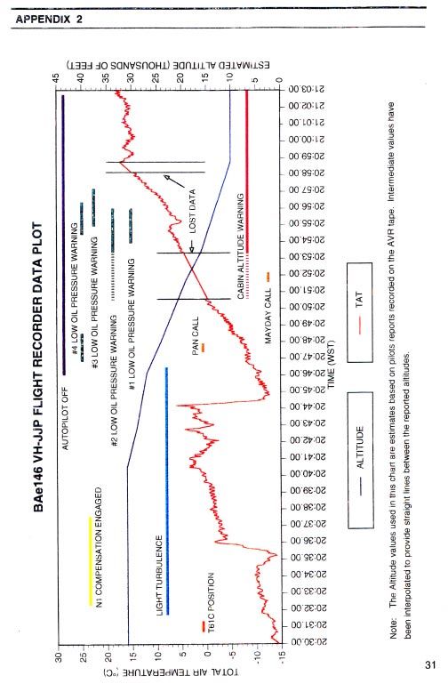
Despite the failure, the recording did contain useful data. A plot of selected parameters was
produced for the period 2030:00 hours to 2103:00 hours, covering the time of this incident
(appendix 2).
1.11.2 Cockpit voice recorder
VH-JJP was equipped with a cockpit voice recorder with a recording duration of 30 minutes.
Because more than 30 minutes elapsed between power being restored on the engines and the
aircraft arriving at Meekatharra, all information pertaining to the occurrence had been over-
recorded.
1.11.3 Engine health monitoring system
The aircraft was equipped with an ELC which recorded a data block of engine parameters
whenever an out-of-limit warning occurred. Each block of data covered 21 seconds of engine
operation from 5 seconds before the triggering event to 15 seconds after. Information from a
number of recorded data blocks was included in section 1.1 of this report.
1.12 Wreckage and impact information
Not relevant.
1.13 Medical and pathological information
Not relevant.
1.14 Fire
Four passengers reported what appeared to be a fire from the engines on the left side of the
aircraft. Post flight examination did not reveal any evidence of an in-flight fire.
51.15 Survival aspects
Not relevant.
1.16 Tests and research
1.16.1 Bleed air demand
The ALF502R-5 engine is fitted with an interstage bleed air overboard dump valve which is
controlled by the FCU and is opened under certain operating conditions to protect the engine
against compressor surge and/or stall. In addition, the aircraft has a number of systems which
require bleed air from the engines. These are:
• outer wing anti-ice (supplied by both engines on the applicable wing);
• inner wing de-ice (supplied by both engines on the applicable wing);
• tailplane anti-ice (supplied by all engines);
• environmental control system (ECS) (supplied by all engines); and,
• engine anti-ice (supplied by the corresponding engine).
It was not possible to positively determine the selection of the ECS. Initial information
indicated it was in the fresh air mode, but later information suggests that it may have been in
the recirculating mode. On this basis, calculations were performed for both cases.
Using data on the bleed air flow rates required by the aircraft and engine systems listed above,
comparisons were made of the maximum bleed air drain on the engines under the conditions
experienced by the aircraft prior to, and after entering, the higher temperature air mass. These
comparisons are summarised as follows:
Event Ambient air Bleed air services Bleed air extraction
temperature operating Fresh Recirc.
Prior to OAT rise -33.4°C ECS 3.0% 1.7%
(ISA + 11°C)
ECS 5.6% 4.3%
plus engine anti-ice
At initial OAT rise -22.4°C ECS 6.1% 4.7%
(ISA + 22°C) plus engine anti-ice
ECS 8.21% 6.9%
plus engine anti-ice
plus outer wing anti-ice
ECS 7.6% 6.2%
plus engine anti-ice
plus tail anti-ice
When power was -22.4°C ECS 9.1% 7.8%
increased (ISA + 22°C) plus engine anti-ice
plus outer wing anti-ice
plus tail anti-ice
At maximum -15.4°C ECS 9.6% 8.3%
OAT (ISA + 29°C) plus engine anti-ice
plus outer wing anti-ice
plus tail anti-ice
6The engine installation instructions specified that the maximum bleed air demand for aircraft
and engine services should not exceed 8% of total air mass flow through each engine. However,
the instructions did permit a total of 9.5% in icing conditions.
The ECS system can be operated in either the fresh air or the recirculating mode. As the above
data shows, operating in the recirculating mode reduces the bleed air demand on the engines
by about 1.2%.
Note that the above calculations apply only when the engine interstage bleed valves remain
closed. If the bleed valves open, the core engine flow is reduced and the percentage of air
extracted increases. Data on the amount of air dumped by the interstage bleed air valves was
not available.
1.16.2 Fuel control unit calibration
Following the incident, the FCUs were removed from the engines and tested.
All the FCUs were within tolerance at the high RPM point (equivalent to 88.6% N2). The units
from nos. 1, 2 and 3 engines were close to the centre of the tolerance band, but the FCU from
no. 4 engine was near the low fuel flow limit of the band.
At the intermediate RPM point (79.2% N2), the FCU from no. 2 engine was outside the upper
limit of the tolerance band.
At the minimum fuel flow point, the FCUs from nos. 1 and 2 engines were outside the upper
limit of the tolerance band.
1.17 Additional information
1.17.1 Engine aspects
Electrical load
In the immediate lead-up to the occurrence, the cabin crew were operating the galley ovens
and other equipment prior to serving a meal. The resultant high electrical load would have
placed additional mechanical load on those engines fitted with generators (nos. 1 and 4
engines).
Factors affecting roll-back
The phenomenon in which aircraft engines lose power as described in section 1.1 is commonly
referred to as engine ‘roll-back’.
At the time of this occurrence, the factors involved in engine roll-back in BAe 146 aircraft were
under investigation by the engine and aircraft manufacturers as a result of three earlier
incidents. These similar incidents, which occurred overseas, involved roll-backs in one, two,
and three engines. However, the VH-JJP occurrence was the first in which all four engines on a
BAe 146 aircraft were affected. All incidents occurred at high altitude (28,000 ft or above), at
higher than standard temperatures (ISA + 10°C or greater), and in moist conditions where
bleed air was being drawn from the engines for airframe and/or engine anti-icing.
The basic causes of roll-back are as follows:
• In the low air densities at high altitudes, the aircraft engines must be operated at
relatively high power settings for the necessary thrust to be developed. Loading on the
engines is increased by higher than standard OATs, by power demands from the engine
for services such as pumps and generators, and by high bleed air demand to the ECS or
anti-ice systems. Under such conditions, the FCUs will schedule a relatively high fuel air
7ratio and the TGTs will, correspondingly, be towards the upper limit.
• As the FCU increases fuel flow to the engine in response to higher loads, a point is
reached where the interstage bleed valves are triggered open to maintain smooth airflow
through the compressor, thereby dumping part of the engine core air overboard and
reducing the power output of the engine. The FCU responds to this by increasing the
fuel flow to the engine until the acceleration limit is reached after which no additional
fuel can be supplied.
• Before this limit is reached, the high pressure turbine will have been extracting an
increasing proportion of the power available from the (reduced) core flow to meet the
needs of the compressor (and other power demands), thereby reducing the power
available to drive the low-pressure turbine which drives the fan. Hence, fan (N1) RPM
will begin to decrease before engine core (N2) RPM shows any significant fall. As N2 RPM
decreases, core air flow falls as does the fuel-air ratio via the FCU. Furthermore, bleed
air represents an increasing percentage of core flow as core air flow falls. Thus, the
process becomes self sustaining unless action is taken to relieve the power extraction
from the engines.
Advice on engine roll-back to aircraft crews
The possibility of engine roll-back during high altitude cruise in high ambient temperatures,
with engine and airframe anti-ice on, was addressed by the aircraft manufacturer in several
Notices to Aircrew prior to the VH-JJP occurrence. Details of these notices were as follows:
1. Operational Notice to Aircrew OP 17 was issued in October 1987 and titled Engine
N1/N2 mismatch with anti-ice selected.
2. Operational Notice to Aircrew OP 22 was issued in May 1991 and replaced OP 17.
It was titled Engine N1/N2/TGT abnormal relationship with airframe anti-icing selected
ON.
3. Operational Notice to Aircrew OP 25 was issued in November 1991 and replaced
OP 22. It was titled Engine bleed band open with airframe outer wing and tail anti-ice
on above 25,000 ft (appendix 3).
The crew of VH-JJP had received OP 25 during the week before the incident. However, they
did not initiate the actions listed in OP 25 because they did not equate the symptoms with
which they were confronted with the description in OP 25.
Company procedures
Company procedures required the use of engine anti-ice if any free moisture was present and if
the OAT was warmer than -35°C. This compares with the minimum temperature for the
existence of supercooled water, as established by laboratory tests, of -40°C.
1.17.2 Other aspects
Crew teamwork
When the cabin crew detected a burning smell in the aircraft cabin, the information was
immediately passed to the cockpit. Four passengers seated on the left side of the cabin reported
seeing signs of fire from the left engine(s) in the form of flames and engines ‘glowing’. At least
one passenger reported this observation to a cabin crew member who did not convey it to the
cockpit as she thought the cockpit crew were already aware of the problem.
8Crew use of oxygen masks
With the pilots wearing oxygen masks, intra-cockpit communications are by way of
microphones fitted within the masks and the cockpit overhead speakers. The aircraft electrical
system is so arranged that, when the generators are off-line and the aircraft batteries are
powering essential electrics, the speaker on the first officer’s side of the cockpit is deactivated,
thereby affecting the quality of intra-cockpit communications.
The purser’s oxygen mask was not fitted with a microphone, so to make PA announcements to
the cabin, he had to remove the mask. Civil Aviation Order 20.11 appendix IV requires crew
members to have a theoretical knowledge of altitude and the effects of hypoxia. However,
pursers do not receive practical training in the effects of hypoxia and, in this instance, the
purser reported that he was not familiar with the physical manifestations of the onset of this
condition.
Flight attendant seating—view into cabin
The flight attendant seating positions were:
• purser adjacent to the left forward door facing forwards;
• position two in the cabin behind the last rear seat on the left side; and,
• position three adjacent to the left rear door, facing rearwards.
This arrangement meant that only the attendant in position two could see the passenger cabin
when seated. This is also the only attendant position without a communications panel.
Regulations do not require the cabin to be under observation by a flight attendant with a
communications panel. However, the cabin crew need to able to see events in the cabin so that
they can pass relevant information to the cockpit.
Facilities exist to install a mirror in the cabin to enable the purser to view most of the cabin,
and all aircraft from this company were delivered with mirrors installed at front and rear
vestibules. Some BAe 146 aircraft operated by the company which were inspected during the
investigation, did have mirrors fitted, but VH-JJP did not, so the purser could not monitor the
passengers whilst seated at his station during the incident sequence.
Cabin equipment/procedures
Interviews with the cabin crew highlighted the following issues:
1. During the descent, the cabin lights flickered on and off and chimes sounded
repeatedly. The cabin crew reported that this alarmed the passengers and made their
task of reading the passenger safety checklist more difficult because of insufficient light.
2. The cabin crew reported difficulty in reading the emergency checklist pages which
were printed in black on grey paper. The purser reported that he used the glow of the
emergency exit lighting to read the cabin announcements. Torches were provided for
the cabin crew but could not be used when both hands were required to hold an
emergency procedures booklet or to support the crew member. The aircraft was not
equipped with an independently powered emergency cabin lighting system for use in
such circumstances.
3. Aisle seated passengers on the three-abreast seating side of the aircraft experienced
difficulties in fitting their oxygen masks due to the limited length of the oxygen tubes.
One passenger pulled the mask from its fitting. In addition, the hoses were not long
enough for the passengers to practice the brace position while wearing their oxygen
masks.
94. The flight attendant at position three experienced difficulty in hearing the speaker
and watching for the call light during the incident. This was because of the location of
the speaker and call light for that position.
5. The purser’s PA announcement instructed passengers to remove certain articles
(including ‘glasses’—presumably spectacles) and to stow them in the seat pocket. At
the end of the announcement the passengers were then instructed to study the safety
card in the seat pocket. This would not have been possible for a passenger requiring
reading spectacles.
Passenger questionnaire
A cabin-safety questionnaire was sent to 47 of the passengers on the aircraft. Replies were
received from 34 passengers. Significant responses were as follows:
1. All respondents reported that they knew the location of the nearest emergency exit,
and had obtained this information from the pre-flight briefing or, because they were
frequent air travellers, already knew the location of exits. One respondent stated that
emergency exits were always half-way along the cabin. In the BAe 146 aircraft there
are no centre-cabin exits.
2. Only three respondents stated that they neither watched nor listened to the pre-flight
briefing. Of the remainder, 24 reported that they listened to and watched the briefing;
3. All except one of the respondents reported that they understood the emergency
briefing from the flight attendant at the time of the incident;
4. Twelve respondents read the safety briefing card prior to the incident;
5. Six respondents found difficulty in adopting the brace position in response to the
purser’s instructions because their head contacted the back of the seat in front.
6. Most respondents commented favourably on the cabin crew’s performance and their
concern for the passengers’ safety. However, some felt that the airline should have
offered some form of stress de-briefing after the event.
Visual wing-ice inspection
The cockpit crew reported being unable to visually confirm the extent of wing icing because
the colour of the wing leading edge offered no contrast against which ice might be seen.
Operations Manual inaccuracies
During the course of the investigation, it was discovered that the manufacturer’s Operations
Manual supplied to and used by the company for the BAe 146 aircraft, contained incorrect
information regarding the way in which bleed air is distributed to the wing anti-ice system.
The company used the information in that Operations Manual, for systems training of aircrew
and engineering personnel.
The same incorrect information was found in the BAe 146 Series 100/200 Type Record
(description of the aircraft and its build standard at the time of certification).
102. ANALYSIS
2.1 The roll-back
The investigation revealed that there were no significant material or calibration deficiencies in
either the aircraft or the engines which would have contributed to the occurrence. The roll-back
occurred under unusual, but not extreme, environmental conditions when the aircraft was
cruising at its maximum approved altitude. When anti-ice was selected in response to the
airframe ice warning, no. 4 engine could not support the additional bleed air drain and
commenced to roll back. This was followed by the other three engines.
ELC data indicated that the initial (no. 4 engine) roll-back probably began 2 to 3 minutes after
the sudden rise in OAT and after the crew had activated the outer wing anti-ice system.
Consequently, five factors can be correlated with the commencement of no. 4 engine roll-back.
These were:
1. a pre-existing bleed air extraction for ECS and engine anti-ice;
2. a decrease in air mass flow through the engine due to lower air density at the
increased temperature;
3. aircraft entry into an area of icing;
4. an increase in bleed air extraction following the selection by the crew of outer wing
anti-ice; and
5. placement of a high mechanical load on nos. 1 and 4 engines by the high electrical
demand at the time.
Calculations showed that the combined effect of the temperature increase and the selection of
engine and airframe anti-ice increased the bleed air extraction from 3% to 9.6% with ECS in
fresh air mode (1.7% to 8.3% with ECS in RECIRC) at the point of maximum OAT. These
higher figures are close to, or slightly above, the maximum bleed air extraction of 8% (9.5% in
icing conditions) stipulated by the manufacturer.
Prior to the incident, the TMS was engaged in the TGT mode with 800°C initially selected.
This was later increased to 840°C, then MCT, and finally the TMS was deselected. The use of
TMS would have inhibited the engine FCUs from initially scheduling maximum fuel flow and
may have accelerated the initial stages of the roll-back. However, after the MCT selection, the
use of TMS would have had no influence on subsequent events.
What direct effect, if any, icing may have had on the initiation of the roll-back could not be
determined. Nevertheless, later in the descent, after the engines had not responded to the
crew’s initial actions, icing of the engine core is likely to have prolonged the roll-back.
The reason for no. 4 engine rolling back first is explained by the FCU calibration figures which
show that, at the high RPM point, the FCU from no. 4 engine was near the low limit of the
tolerance band while the other three engines’ FCUs were close to the centre of the band.
Consequently, the maximum fuel flow available to no. 4 engine was less than that available to
the other engines.
ELC data shows that the N2 RPM for all engines remained steady until the N1s had decreased
to below about 60% when the N2s also began falling. While the N2s remained constant, the
TGTs were maintained at the MCT value by the FCUs. After the N2s fell below about 88%, the
TGTs also began to decrease, indicating a lower fuel-air ratio. These trends in TGT indicated
correct operation of the FCUs. The engines continued to roll back until a sub-idle condition
was reached.
11Recovery from the roll-back did not commence until the aircraft reached the forecast freezing
level. This is consistent with airflow through the engine cores being degraded by a build-up of
ice. The failure of the engines to recover or stabilise after the crew actions of shutting down and
restarting engines, adjusting thrust levers, and selecting all engine and airframe anti-ice, and
the ECS system off, is also consistent with ice already having formed within the compressor
and affecting the airflow through the engine cores. Icing of the core under a low power or sub-
idle condition was likely because any bleed air that might have been available for anti-ice use
would have been at too low a temperature to have had any useful effect.
2.2 Cockpit crew actions
The flight crew were aware of Operational Notice 25 but because they did not associate the
cockpit indications with the information contained in Operational Notice 25, they used a
logical and knowledge-based approach in attempting to regain normal engine operation. They
did not remove all bleed air and mechanical load from the engines until the later stages of the
occurrence, even though post-event analysis indicates that early implementation of these
actions may have aided in the recovery from the initial stages of the roll-back development.
When the crew did initiate the actions, it is likely that they were ineffective because, by that
time, the engines were affected by ice within the compressor sections. Under these
circumstances, there was little the crew could do until the ice had melted and the compressor
airflow had returned to normal.
There were shortcomings in Operational Notice 25, namely:
1. It did not address the possibility that more than one engine could be affected.
2. It did not mention the possibility of further reduction or possible roll-back to a sub-
idle condition if the crew did not take prompt action.
3. It did not address the possibility of the affected engine failing to respond to the
recommended corrective action.
4. It suffered from technical wording that did not emphasise factors which would have
been of prime interest to the crew in recognising the initial stages of roll-back.
The initial symptoms as described by the crew were not aligned with those set out in
Operational Notice 25. The increase in OAT followed by the airframe ice warning and then
the deterioration in aircraft performance were consistent with airframe icing. The engine N1
RPM indication remained steady until the aircraft had descended to about FL 290. When the
crew saw the engine N1 RPM indications approaching 75%, the wing and tail de-icing was
selected off. However, both ECS packs and engine anti-ice and bleed air were left on,
probably prolonging the roll-back. The actions of the crew, therefore, were partially in line
with those listed in Operational Notice 25 and were consistent with good cockpit resource
management given the deficiencies in the Operational Notice and the initial indications of
the problem.
The inaccuracies in the manufacturer’s Operations Manual and subsequent training given to
the flight crew based on this inaccurate information, had no bearing on the development of the
roll-back incident. The crew’s actions were based on their general understanding of the bleed
demand and not on the specifics of the distribution system as described in the Manual.
2.3 Use of engine anti-ice
The company procedure of using engine anti-ice if any free moisture is present and the OAT is
above -35°C (compared to the minimum temperature for supercooled water of -40°C) does
not make allowance for the possibility of warm/moist air encounters such as occurred in this
12instance. A change in the temperature above which engine anti-ice is used to -40°C would
provide a greater buffer in the event of a warm/moist air encounter.
2.4 Cabin safety aspects
The cabin crew performed their duties in accordance with training standards, despite being
placed in an unforeseen and unrehearsed set of circumstances. However, during the
investigation, a number of deficiencies were identified which impinge on cabin safety. These
are mentioned in section 1.17.2 and, while they in no way related to the basic factors leading
to this incident, they could affect the safety of the passengers and cabin crew in certain
circumstances.
Some of these deficiencies should have been discovered or eliminated during certification
and/or training. That they were present indicated that both certification and training processes
were not structured to highlight adequately some safety problem areas. Safety
recommendations regarding these deficiencies are made at the end of this report.
133. CONCLUSIONS
3.1 Findings
1. The pilots were qualified and medically fit for the flight.
2. The aircraft was serviceable and its weight and centre of gravity were within limits.
3. While passing about 30 NM abeam a thunderstorm at FL 310, the aircraft encountered a
pool of moist air which was significantly warmer than the surrounding air, prompting the
crew to activate the engine and aircraft anti-ice systems.
4. The combined effect of the temperature increase and bleed air demand for the anti-ice
systems caused the bleed air demand on the engines to be close to or slightly above the
maximum stipulated by the engine manufacturer. The response of the FCUs was initially
inhibited by operating the TMS in the TGT mode.
5. The interstage bleed opened and the combination of airframe and engine anti-ice bleed
and compressor interstage bleed resulted in a fuel flow demand greater than the FCU could
provide.
6. No. 4 engine was the first to roll back, followed shortly thereafter by the other three
engines.
7. The effect, if any, of icing on the initiation of the roll-back could not be determined.
8. During the descent, when the engines did not respond to the crew’s attempts to restore
power, icing of the engine cores probably prolonged the roll-back.
9. All engines returned to normal operation after the aircraft descended below the freezing
level (about 13,500 ft).
10. There were deficiencies in Operational Notice 25 issued by the aircraft manufacturer which
addressed the possibility of engine roll-back during high altitude cruise in high ambient
temperatures, with engine and airframe anti-ice on.
11. The actions of the cockpit crew were in accordance with the information available to them
12. Information concerning possible signs of fire in the engines on the left side of the aircraft
was not passed from the cabin to the cockpit crew.
13. The speaker on the first officer’s side of the cockpit was deactivated when the aircraft
batteries were powering the essential electrics, degrading the quality of intra-cockpit
communications.
14. No microphone was fitted to the purser’s oxygen mask to allow the purser to make PA
announcements while wearing the mask.
15. Emergency procedures checklists for the cabin crew were difficult to read in reduced light
conditions.
16. The only flight attendant seating position offering a view into the passenger cabin was not
equipped with a communications panel.
17. Aisle passengers on the three-abreast seating side of the aircraft had difficulty fitting their
oxygen masks due to the limited length of the tube to the mask.
143.2 Significant factors
1. During high altitude cruise, the aircraft encountered a pool of moist air which was
significantly warmer than the surrounding air.
2. The selection of engine and airframe anti-ice by the crew placed a bleed air demand at, or
slightly above, the maximum on the four engines, causing them to ‘roll back’.
3. An Operational Notice published by the aircraft manufacturer did not provide information
of sufficient clarity to enable the crew to recognise and deal with the ‘roll-back’.
4. Engine core icing probably prevented the recovery from the ‘roll-back’ until the aircraft
descended below the freezing level.
154 SAFETY ACTION
4.1 Safety actions taken
(i) Following this occurrence the Civil Aviation Authority approved and issued Flight Manual
Supplement A/146-100/8 dated 08:07:92 titled, “Maximum Operating Altitude”. This
amendment is reproduced below:
“Maximum Operating Altitude
Pending further investigation into the problems arising from the use of anti-icing
systems in certain conditions above 25000 feet and to reduce the possibilities of
engine difficulties, the following must be employed until further notice:
1. The maximum operating altitude is 28000 feet by night and 31000 feet by day,
subject to condition 2 below.
2. Operating above 25000 feet in known or forecast icing conditions is prohibited.
It is emphasised that the presence or forecast of any cumuliform or convective (ie
potential icing) cloud above FL250 on or adjacent to the proposed route (including
possible alternates) constitutes ‘known or forecast icing conditions’ for the purpose
of this limitation and the aircraft must accordingly be dispatched with a planned
cruise level at or below FL250.”
(ii) Reference issue 5, para 1.17.2.– Cabin Equipment/Procedures. The operator has modified
procedures to retain reading spectacles until the safety card has been studied. Both the
card and the spectacles are then stowed.
(iii) Reference para 1.16.2.– Fuel Control Unit Calibration. Since this occurrence, the engine
manufacturer has altered the FCU calibration requirements to increase the maximum
available fuel flow which will improve the engine tolerance to a high mechanical
load/bleed air extraction. The fuel flow at which the interstage bleeds open has also been
increased slightly. These changes have been successfully tested at altitude, but not at the
most adverse combination of possible operating conditions within the flight envelope.
4.2 Safety Advisory Notices
In addition to the formal recommendations above, the Bureau of Air Safety Investigation also
makes the following Safety Advisory statements for further consideration:
(i) That the BAe 146 aircraft manufacturer, in consultation with the aircraft operators, give
consideration to the application of a contrast colour band along the lower leading edges of
the wings which may give a visual indication, and confirmation, of ice build up.
(ii) That the Bureau of Meteorology continue their research to develop and document the
phenomenon of the anomalous air zones which this aircraft encountered, with the view to
educating operators and pilots worldwide, in identifying their existence and on
procedures and methods for avoidance.
(iii) That the Australasian Airlines Flight Safety Council, and all RPT operators, give
consideration to, and take an active part in, the development of a post occurrence stress
trauma counselling/debriefing infrastructure for passengers.
164.3 Final recommendations
The Bureau of Air Safety Investigation recommends that:
1. The Civil Aviation Authority minimise the risk of engine roll-back on BAe 146 Aircraft by
ensuring that the aircraft can be operated throughout the certificated operational flight
envelope, under all environmental conditions, with an adequate margin of safety above
the threshold at which engine roll-back may occur.
2. The Civil Aviation Authority, in consultation with the engine and aircraft manufacturers,
ensure that the BAe 146 aircraft flight manual contains unambiguous instructions for the
operating crew to recognise and correct a developing engine roll back situation.
3. The Civil Aviation Authority, in consultation with the aircraft manufacturer, identify those
special operating procedures which may apply to limit the total mass bleed air flow and
ensure that the procedures for doing so are adequately documented in the procedures
section of the aircraft flight manual.
4. The Civil Aviation Authority, in consultation with the engine and aircraft manufacturers
and BAe 146 operators, and giving consideration to the weather phenomenon which
existed at the time of this occurrence, review the best temperature at which the engine
anti-icing should be switched ON and amend the pilots operating instructions
accordingly.
Note: During this investigation British Aerospace amended their Operations Manual for
this aircraft to reflect the lower temperature of -40°C for the use of engine anti-ice.
5. The Civil Aviation Authority ensure that for this and other aircraft certificated for
operations in the RPT category, the passenger oxygen masks have sufficient reach to enable
all cabin occupants to don and use masks from their normal seated positions.
6. The Civil Aviation Authority ensure that cabin crew emergency procedures booklets/
manuals are legible in the reduced light conditions of the cabin during an emergency.
Note: The operator’s Emergency procedures books have been reprinted using black print
on white background.
7 The Civil Aviation Authority, in consultation with BAe 146 Operators, evaluate and
consider changes to ensure that surveillance of the passenger cabin is possible by members
of the cabin crew when seated, who are able to communicate with the other cabin crew
members and the flight crew.
8. The Civil Aviation Authority, in consultation with the Civil Aviation Authority (UK) and
the aircraft manufacturer evaluate the certification of the flight crew communication
system during an emergency, when both flight crew members are wearing oxygen masks
and with essential electrical systems in use, to ensure that the intra cockpit
communications are maintained and not compromised by deactivation of the first
officer’s overhead speaker.
9. The Civil Aviation Authority ensure that the senior cabin attendant (the purser) is capable
of immediate operation of the intercom and Public Address (PA) system in accordance
with Civil Aviation Order 20.11 para 14.1.6, by providing that person with access to an
oxygen mask which has a microphone installed.
10. The Civil Aviation Authority consider changes to CAO 20.11 para 12 to include as a
requirement that flight crew members and those cabin crew members designated as purser
and/or senior crew should have undertaken practical training in the symptoms and effects
of hypoxia in addition to the theoretical knowledge requirements.
17You can also read