Combined Heat and Power Microturbines - Water ...
←
→
Page content transcription
If your browser does not render page correctly, please read the page content below
Combined Heat and Power Microturbines
Introduction
This fact sheet provides a review of combined heat and power (CHP) technologies for
use at water resource recovery facilities (WRRFs). CHP, also called “co-generation,” is
defined as the concurrent production of electricity and thermal energy from a power-
generating device. Individually, microturbines are on the smaller end of the spectrum of
CHP units and, at 92 MW of total installed capacity, they only comprise 0.1% of the total
CHP capacity in the United States (U.S. Department of Energy, 2015). Their small size
and modular design allow for widespread applicability, and, in terms of number of CHP
sites using microturbines as their chosen technology, microturbines comprise
approximately 8% of the U.S. CHP market (U.S. Department of Energy, 2016).

Microturbines make use of a Brayton cycle, where air is first drawn into the engine and
compressed to high pressure by a radial compressor and is then mixed with fuel in the
combustion chamber and continuously ignited. The compressed air is used to drive a
turbine that provides torque to both the compressor drawing the air in and an electrical
generator. Modern microturbines also make use of a recuperator stage, where hot
exhaust air passes by the compressed air entering the combustion chamber, preheating
the air before combustion and increasing thermal efficiency.

Microturbines of 30 to 300 kW are an economical option, with the ability to parallel
multiple modular units (U.S. Department of Energy, 2016). In December 2019, only 36
sites with a total capacity of 7.4 MW within the U.S. water resource recovery industry
were demonstrating this technology and its economic benefits (U.S. Department of
Energy, 2019). U.S. installations at WRRFs range in size from 30 kW to 1.6 MW (U.S.
Department of Energy, 2019).

Fundamentals
Most microturbine installations use natural gas for fuel in CHP applications. This fact
sheet emphasizes operation at WRRFs using anaerobic digester gas as a renewable
energy source. Anaerobic digestion is a good fit for CHP because of the constant heat
demand of the digesters. CHP does not provide energy efficiency benefits without a
need for the heat recovered.

                           Copyright © 2021 by the Water Environment Federation.
                    All Rights Reserved. Permission to copy must be obtained from WEF.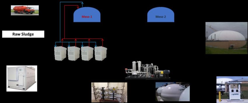
The electrical efficiency of microturbines is comparatively low, ranging from 25% to 29%
higher heating value (HHV) and increasing with the size of the unit. Heat recovery from
a microturbine is from the exhaust gas that exits the recuperator at 260 to 315 °C (500
to 600 °F). Hot exhaust gases can be used for process heating needs, such as drying or
preheated combustion air, but typically a heat exchanger extracts the heat for hot water
or steam. Exhaust heat recovery boosts the overall fuel to a useful energy efficiency of
65% to 70% HHV (U.S. EPA, 2015).

In WRRF applications where digester gas is used in place of pipeline natural gas,
digester gas compression and treatment are required. Digester gas is saturated with
moisture and may contain hydrogen sulfide and siloxanes. Siloxane cannot be tolerated
by microturbines because silicon dioxide is formed during combustion of siloxane, which
destroys lightweight turbine blades. Hydrogen sulfide is tolerated, but moisture removal
is required to minimize corrosive conditions in the gas piping system and for
pretreatment for siloxane removal.

Because of the pressure used in the combustion chamber of a microturbine, adequate
fuel supply pressure is critical to microturbine operation. Microturbines require fuel
supply pressures in the range of 400 to 1000 kPa (60 to 40 psig) (U.S. EPA, 2015).
Safety considerations for gas compression and microturbine installations are covered in
Standard for the Installation and Use of Stationary Combustion Engines and Gas
Turbines (NFPA 37, 2021) and Standard for Fire Protection in Wastewater Treatment
and Collection Facilities (NFPA 820, 2020) for installation at WRRFs. Enclosed gas
compressor rooms are considered Class 1, Division 1, Group D hazardous-rated
spaces. Ventilation at 12 AC/h reduces the Division 1 envelope to within 2 m (5 ft) of the
gas-processing equipment (NFPA 820, 2020).

Digester gas production can vary at WRRFs. With this variability in fuel supply, gas
storage is, in most cases, essential to maximize CHP system production and minimize
flaring. Storage is also highly beneficial to a “peak-shaving” strategy, whereby CHP
system operation is maximized when thermal and electric demands are greatest,
minimizing the peak energy that must be acquired by other means. Microturbines will
lose efficiency at partial load; for this reason, multiple smaller units can be used so that
the units online will operate at full load, and individual units are cycled on and off. If an
individual turbine must be operated at partial load, the thermal side is less affected
because exhaust temperatures do not drop significantly, and the efficiency loss in part-
load electric generation can be compensated for with heat recovery. The drop in
electrical efficiency reduces microturbines’ suitability for load-following applications.
Load following is an automation strategy where the output of the microturbine
modulates to meet the available load. Because of the loss of efficiency at partial load

                            Copyright © 2021 by the Water Environment Federation.
                     All Rights Reserved. Permission to copy must be obtained from WEF.
and the modular nature of the microturbines, variable loads can be offset by
strategically turning microturbines in an array off and on.

Another important consideration for microturbines is the reduction in electrical efficiency
as the inlet air temperatures rises. Because the inlet air is compressed, the reduced
efficiency is a result of more parasitic loads being required to compress the warm inlet
air. Note that this effect reduces power output and efficiency.

Techniques for inlet air cooling can be applied to microturbines. Evaporative cooling
uses a fine water mist to lower the air temperature through evaporation. This technique
would be applicable to high daytime temperatures at which relative humidity is moderate
with separation of the wet and dry bulb temperatures.

Characteristics/Applicability
Microturbines have the following attributes that may drive their selection and application
at WRRFs:

       •   Compact, modular design and low output capacities
       •   Ability to use low-energy fuel
       •   Low emissions
       •   Low maintenance compared to internal combustion engine (ICE)
       •   Quiet operation

Microturbines are applicable to WRRFs with digester gas available to support up to 500
kW of CHP. For CHP systems below 200 kW, microturbines are a preferred technology.
Generally, digester gas production in the range of 850 to 7100 Nm3 per day (30 000 to
250 000 scfd), corresponding to 500 kW of generating capacity, would be appropriate
for microturbine systems at wastewater treatment facilities. Higher gas production
supports ICE engine generators as a cost-effective CHP system.

The higher efficiency of ICE systems is offset by the high maintenance costs relative to
power production for small engines. Lubricants, coolant, plugs, and regular rebuilds are
associated with proportionately higher costs. If maintenance is performed using WRRF
staff, the hours are significant; alternatively, contract maintenance is an ongoing
expense. In WRRFs that have experience with ICE systems, the clean, quiet operation
of microturbines can be a relief from engines.

In states such as California, low air emissions may be a key advantage, and, in less
stringent environments, an air permit may not be required.

                            Copyright © 2021 by the Water Environment Federation.
                     All Rights Reserved. Permission to copy must be obtained from WEF.
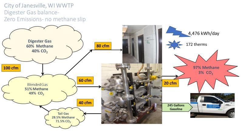
Microturbines can use gaseous fuels as low as 13 MJ/Nm3 (350 Btu/scf) lower heating
value (LHV) (Capstone Turbine Corporation, 2008). This attribute was used in
Janesville, Wisconsin, to recover methane slip from the tail gas from a gas upgrading
system. Figure 1 shows the overall digester gas utilization system at Janesville, and
Figure 2 shows an example energy balance for the production of RNG for CNG vehicle
fuel. Janesville is a unique application, but, in general, microturbines are more flexible in
suitable fuels than ICE.

 200 kW Microturbine

Figure 1. Janesville, Wisconsin, Digester Gas System Featuring Microturbines
(Reprinted with permission from Janesville Wastewater Utility)

                              Copyright © 2021 by the Water Environment Federation.
                       All Rights Reserved. Permission to copy must be obtained from WEF.
Figure 2. Energy Balance for Janesville, Wisconsin (100 cfm = 170 Nm3/hr; 245 gal
= 927 L) (Reprinted with permission from Janesville Wastewater Utility)

Heat recovery from microturbines is straightforward, with units having either integral
heat recovery for hot water production, external heat exchangers, or ducting to direct
hot air applications. Heat recovery is not a component of the cooling system as is the
case for engine systems. Hot exhaust is diverted away from the heat exchanger if not
needed, and the exhaust temperature is monitored and water flow is diverted to prevent
the stack from getting too cool.

Support Equipment—Fuel System
Microturbines can burn a wide range of liquid and gaseous fuels. This fact sheet
discusses the fuel system requirements for using digester gas as the microturbine fuel.
Digester gas produced from municipal anaerobic digesters contains siloxane at levels
that will damage microturbines, and siloxane must be removed for digester gas to be
used in a microturbine.

Digester gas is fully saturated with water because it is produced within anaerobic
digesters. Digester gas piping is designed to collect and trap condensed moisture from
the gas, but digester gas should be further dried as part of an overall treatment system.

Hydrogen sulfide (H2S) is an odorous gas component of digester gas that forms
corrosive sulfuric acid in the presence of moisture and contributes sulfur dioxide (SO2)
to exhaust gases, which may threaten air quality.
                            Copyright © 2021 by the Water Environment Federation.
                     All Rights Reserved. Permission to copy must be obtained from WEF.
Siloxane is typically removed by activated carbon. The carbon must be dry to adsorb
siloxane, and H2S competes for carbon adsorptive capacity, so a complete treatment
system includes removal of H2S, moisture, and siloxane.

Most anaerobic digesters operate at a pressure of 1 to 4.5 kPa (4 to 18 in) H2O.
Microturbines require digester gas fuel to be delivered at 400 to 1000 kPa (60 to 140
psig) (U.S. EPA, 2015). Digester gas compression equipment is typically included as
part of the overall gas treatment train. Hydrogen sulfide removal typically requires moist
gas that can be incorporated ahead of compression and subsequent treatment steps.
H2S can be removed by iron-based adsorbents, activated carbon, or wet scrubbers,
incorporating chemical or biological methods (or both).

The pressurized gas train includes moisture and siloxane removal before the
microturbine fuel train, which may include additional filters and pressure regulators.

NFPA 820 (2020) provides fire protection standards for digester gas handling and
processing at WRRFs. Digesters and gas treatment facilities are rated as hazardous
spaces that may require special electrical construction depending on separation
distances and ventilation.

Operations and Maintenance
Modes of Operation
As with any Brayton cycle turbine, microturbines require the compressor section to be
rotating before combustion can occur. To start the microturbine, the generator is run as
a motor, providing torque to the microturbine shaft until an adequate speed is reached.
Power to start the units can be obtained from a grid connection; however, for black start
capability, a battery pack charged by the microturbine is required.

The operating speed of microturbines and their generators is very high, up to 60 000
rpm (U.S. EPA, 2015). The bearings are often air lubricated to reduce wear, and most
microturbines incorporate a generator on the same shaft to make the package as
compact as possible. Microturbines without air-lubricated bearings make use of ceramic
oil-lubricated bearings that require oil filters and pumps, adding to capital and
maintenance costs.

The high operating speed means that a microturbine generator cannot interface directly
with the grid, and units are equipped with a gearbox or solid-state electronics that
convert the high-frequency output to grid frequency at 50 or 60 Hz (U.S. EPA, 2015).
When the microturbine parallel to the utility it is called the grid-connect mode. Grid-
connect is contrasted to standalone operation mode where the microturbine is
                            Copyright © 2021 by the Water Environment Federation.
                     All Rights Reserved. Permission to copy must be obtained from WEF.
commanded to a specific output power level and typically includes emergency battery
packs that are used to provide power to remote sites when electricity is not available.
Some microturbines are also equipped with dual-mode operation.

Microturbine systems are also available in two general types: simple and recuperated.
The simple microturbine energy conversion efficiency is low, at approximately 15%.
Commercially available microturbines for application at WRRFs are recuperated units
so simple microturbines will not be discussed further. Recuperated microturbines use
waste heat to heat compressed air between the compressor stage and the combustion
chamber. The overall conversion efficiency is between 26% and 32% on a recuperated
microturbine. With both types, waste heat capture for hot water can raise overall co-
generation efficiency to 80% (U.S. Department of Energy, 2016).

Maintenance Requirements
Maintenance requirements for microturbines are fewer than those of ICEs because of
the small number of moving parts and lower operations and maintenance costs
associated with microturbines. These costs include routine inspections, scheduled
repairs and replacement, preventive maintenance, and labor. Recommended preventive
maintenance intervals range between 2000 and 8000 hours, which can be extended
longer if equipment are operated above a normal temperature of 10 °C (50 °F) (U.S.
EPA, 2017).

Preventive maintenance activities primarily consist of inspecting inlet air and external
fuel filters and battery packs. Each battery pack must be fully charged before storage
and charged again before being brought back into service. Battery packs are used in
stand-alone mode. The total life of a microturbine is estimated to be 40 000 run hours
(U.S. EPA, 2017).

Case Studies
Janesville, Wisconsin, Wastewater Treatment Plant
Janesville commissioned four 65-kW Capstone microturbines in November 2010. The
microturbines replaced two Waukesha engine-generators. The microturbines are fueled
by digester gas produced by three anaerobic digesters. Gas storage is provided by a
dual membrane cover on one digester. Digester gas is treated for H2S removal with an
iron sponge followed by a skid-mounted system that includes gas compression,
moisture removal, and siloxane removal. In 2012, a 200-kW microturbine and a carbon
dioxide removal system were added to produce renewable natural gas (RNG) to be
used as fuel for Janesville’s compressed natural gas (CNG) vehicle fleet.

                            Copyright © 2021 by the Water Environment Federation.
                     All Rights Reserved. Permission to copy must be obtained from WEF.
The Janesville digesters produce approximately 3685 Nm3 per day (130 000 scfd) of
digester gas that is used in the microturbines or to produce RNG. A recent summary of
the generated energy is show in Table 1 below. The data summarized in Table 1 was
provided by the Janesville Wastewater Utility.
TABLE 1. JANESVILLE GENERATED ENERGY SUMMARY
2016 2017 2018 2019
Digester Gas Production
(MMscf) 48 47 49 46
Digester Gas Production
(Dtherm) (LHV) 26 068 25 730 26 696 25 382
CNG (Dtherm) 517 491 524 582
Net digester gas to
microturbines (Dtherm) 25 552 25 239 26 172 24 800
Annual Generated Electricity
(kWh) 1 937 800 1 817 800 1 862 296 2 007 694
Average Annual Power
Generation (kW) 219 208 218 229
Overall efficiency of generation
(%) 26% 25% 24% 28%
Heat Rate (Btu/kWh) 13 186 13 884 14 054 12 353
65kW microturbine hours 15 597 20 569 26 265 18 283
200kW microturbine hours 7186 6450 4254 5420
% hours 65 kW 68% 76% 86% 77%
% hours 200 kW 32% 24% 14% 23%
Average 65 kW Generation 51 45 47 57
Average 200-kW Generation 158 138 146 177
Heat Recovered 65 kW
(Dtherm) 3083 3558 4780 4038
Heat Recovered 200 kW
(Dtherm) 4545 3571 2478 3831
The electricity generated by the microturbines is sold to Alliant Energy under a power
purchase agreement (PPA). The PPA pays $0.12 per kWh during on-peak hours and
$0.074 per kWh during off-peak hours. The average rate paid is $0.093 per kWh. Table
2 shows a recent energy cost and revenue summary for the WRRF.
Copyright © 2021 by the Water Environment Federation.
All Rights Reserved. Permission to copy must be obtained from WEF.TABLE 2. JANESVILLE ENERGY COST AND REVENUE SUMMARY
2016 2017 2018 2019
Purchased Electricity Cost $467,798 $497,490 $465,784 $495,984
Generated Electricity
Revenue $(179,708) $(168,058) $(172,916) $(187,055)
Net Electricity Cost
$288,090 $329,433 $292,868 $308,929
Average Generated Revenue
($/kWh) -0.093 -0.092 -0.093 -0.093
Average Purchased Cost
($/kWh) 0.080 0.081 0.082 0.082
WRRF Natural Gas Cost $23,204 $31,979 $34,401 $25,834
Net Heat Recovery Summer
(Dtherm) 2403 2206 2202 2202
Heat Recovery Winter
(Dtherm) 4493 4199 2386 4635
Net Purchased Energy Cost $317,927 $368,953 $330,912 $341,941
CNG revenue at $2.50
gasoline gallon equivalent* ($11,327) ($10,760) ($11,492) ($12,759)
Net Energy Cost $299,967 $350,651 $315,777 $322,003
*1 GGE = 3.74 liter equivalents = 120 MJ
The data presented in Table 2 is based on utility bills and plant operating data provided
by the city. The revenues generated from the microturbine project represent a 7-year
payback for the project.
References
Capstone Turbine Corporation. (2008). C200 technical reference.
http://regattasp.com/files/410066C_C200_Tech_Ref.pdf
National Fire Protection Association. (2020). NFPA 820: Standard for fire protection in
wastewater treatment and collection facilities. https://www.nfpa.org/codes-and-
standards/all-codes-and-standards/list-of-codes-and-standards/detail?code=820
Copyright © 2021 by the Water Environment Federation.
All Rights Reserved. Permission to copy must be obtained from WEF.National Fire Protection Association. (2021). NFPA 37: Standard for the installation and
use of stationary combustion engines and gas turbines.
https://www.nfpa.org/codes-and-standards/all-codes-and-standards/list-of-codes-
and-standards/detail?code=37
U.S. Department of Energy. (2019). Combined heat and power and microgrid
installation databases. doe.icfwebservices.com/downloads/chp
U.S. Department of Energy. (2015). Combined heat and power installation database.
https://betterbuildingssolutioncenter.energy.gov/chp/solutions-at-a-glance/us-
doe-chp-installation-database
U.S. Department of Energy. (2016). Combined heat and power technology fact sheet
series—microturbines. https://www.energy.gov/sites/prod/files/2016/09/f33/CHP-
Microturbines_0.pdf
U.S. Environmental Protection Agency. (2017). Catalog of CHP technologies.
https://www.epa.gov/chp/catalog-chp-technologies
U.S. Environmental Protection Agency. (2015). Catalog of CHP technologies. Section 5:
technology characterization—microturbines.
https://www.epa.gov/sites/production/files/2015-
07/documents/catalog_of_chp_technologies_section_5._characterization_-
_microturbines.pdf
Authors
Jay Kemp, PE, BCEE, Black & Veatch
F. Michael Lewis, PE
Copyright © 2021 by the Water Environment Federation.
All Rights Reserved. Permission to copy must be obtained from WEF.Samuel Gerber, CDM Smith
Matthew T. Goss, PE, PMP, CEM, CEA, CDSM, LEED AP, CDM Smith
Pooja Sinha, EIT, ENV SP, QISP, Stantec Consulting Services, Inc.
Reviewer
Vincent Nazareth, R.V. Anderson & Associates
Keywords
Microturbine, gas, heat recovery, energy, CHP, fuel, power, digester
Copyright © 2021 by the Water Environment Federation.
All Rights Reserved. Permission to copy must be obtained from WEF.You can also read