COMPACTFLAT S15 AERODYNAMIC. STABLE. INTELLIGENT - Aerocompact
←
→
Page content transcription
If your browser does not render page correctly, please read the page content below
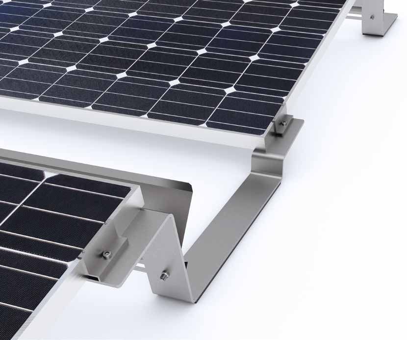
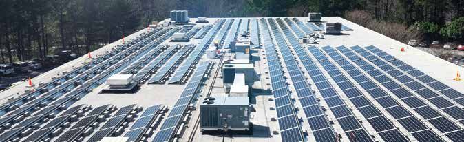
COMPACTFLAT
COMPACTFLAT S15
AERODYNAMIC. STABLE. INTELLIGENT.
Compact and tested substructure for the single-sided
stand-mounting of PV modules on flat roofs

The system, as part of the COMPACTFLAT product range, is an aerodynamic south-substructure
for the fixing and aligning of framed PV modules on flat roofs. It is available at an incline of
15° and with a choice of different row spacing.
1 kWp/
                                                        2.5–5 min.
      YEARS PRODUCT   WIND TUNNEL-   TÜV-CERTIFIED AS                PATENTED
        WARRANTY         TESTED        PER UL 2703

The aerodynamic design boasts exceptional structural properties and requires considerably
less ballast than other systems on the market. Due to the special “spring effect” of the feet,
the substructure adjusts optimally to the conditions of the surface structure. Since the
design is not rail-bound, water drainage is provided on all sides.

Like the COMPACTFLAT S10+, the COMPACTFLAT S15 also has a 25-year warranty, has been
wind tunnel-tested, TÜV-certified in line with UL 2703, and is supplied with a pre-installed
building protection mat. With special loading tests, all variants were tested and approved by
TÜV Rheinland in accordance with UL 2703, as well as a fire test in line with UL 1703. The wire
management solution for the string-wiring of module rows is UL-certified and available as an
accessory with the substructure.

The COMPACTFLAT S15 is stored in our 3D engineering software AEROTOOL.
The AEROCOMPACT ® customer center is able to issue clear and competent project reports
based on empirical data (wind load, snow load, structural analysis).

The COMPACTFLAT S15 is delivered partly pre-assembled, including a newly developed
building protection mat – with long-term durability testing.

This system version with ballast trays is primarily used in areas with high wind loads and on
roofs with a low point-loading capacity. The key advantages of this installation version are the
extra ballast which can be installed for each module on the one hand, and the even distribution
of point loads on the roof surface on the other. The ballasttray can also be deployed if roof
graveling is used as ballast. The gravel is then filled in the plate tray for weight.

With only three main components, the COMPACTFLAT S15 achieves an exceptional
price-performance ratio. In addition to the attractive system price, the simple installation
and high transport density of the innovative system saves time and resources.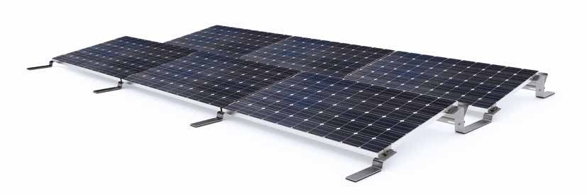
ARRAY MEASUREMENTS

                                                                          18°
                                               125
        S15 – 790 mm spacing                                                                        - 105
                                                                                                         0 mm
                                                                                              950                     240
                                                                                                                      200
                     108

                                                                                                                                       359
                                                                                                                                  50
                                   15°
             270                                              694                                                     270

              303                                             790                                                     333

                                                                                                                                             COMPACTFLAT
                                          1704 - 1807

                                                                    25°
        S15 – 571 mm spacing             125
                                                                                           0 mm
                                                                                      - 105
                                                                                950
                                                                                                                240
                     108

                                                                                                                            359
                                                                                                                200

                                                                                                                      50
                                   15°

              270                                       475                                                     270
              303                                       571                                                     333

                                     1486 - 1588

         TECHNICAL DATA
                                     Aerodynamic installation system for the stand-mounting of framed
         Description                 PV modules on flat roofs.
                                     On foil and bitumen roofs with and without heat insulation beneath
         Scope of use                the sealing, as well as on concrete roofs; can be adapted for gravel
                                     and green roofs upon request
         Module dimensions           950–1,050 mm x 1,475–2,080 mm (width x length)
         Installation angle          15°, unilateral
                                     COMPACTFLAT S15 (18° internal shading angle): 790 mm
         Row spacing                 COMPACTFLAT S15 (25° internal shading angle): 571 mm
         Distance from the roof      Approx. 60 mm; potentially less on gravel roof
         surface / floor surface

         Distance from roof edge 1,200 mm (less corner spacing upon request); roof areas F and G
                                 as per EN 1991-1-4 can be covered
         Max. building height        25 m (adapted for taller buildings upon request)
         Max. roof pitch             Up to 5° possible without roof anchors; above 5° only with roof anchors
         Max. field size             12 x 10 rows; 120 modules
         Min. field size             1 rows for every 2 modules
         Wind load                   Suction load up to 2.4 kN/m2
                                     Pressure load of COMPACTFLAT S15 Standard up to 2.4 kN/m2
         Snow load
                                     Pressure load of COMPACTFLAT S15 Alpin up to 4.4 kN/m2
         Design/stability            Software-supported based on wind tunnel analyses
         verification
                                     Sufficient structural load-bearing capacity of the roof structure and
                                     the building's supporting structure, as well as adequate compressive
         On-site requirements        strength of the roof structure, must be ensured on site. The general
                                     terms and conditions, terms of warranty, and the user agreement apply.
                                     The list of approved modules is provided by AEROCOMPACT®;
         Module approval
                                     individual approvals through the module manufacturer
                                     Module clamps with grounding pins, flat-roof brackets, wind deflector
         Components                  plates, ballast stones; optional lateral plates, ballast trays, roof anchors
                                     Bearing connecting parts made from aluminum EN AW 6060 T64;
                                     module clamps made from aluminum EN AW 6063 T66; screws made
         Materials                   from stainless steel A2-70; wind deflector plates and ballast trays
                                     made from steel with aluminum–zinc coating; building protection
                                     mat made from polyester fleece
Conception and design: Welke Consulting Gruppe®, Siegen, Germany
›M odule clamps with integrated › Q uickest installation: 1 kWp /
grounding pins 5 min. / 2 people
› N o roof penetration necessary › O ptimized wind suction openings
› A lso suitable for roof edge areas › Low transport costs
› M ain structure produced from › T ÜV-certified as per UL 2703
aluminum and stainless steel › W ind tunnel-tested
› Water drainage provided on all sides › E ngineered in Europe
› O ptimum module ventilation › G eneral building inspectorate
› P re-installed building protection mat approval applied for
› 7 00 kWp per truck or 40-foot container › 2 5 years product warranty
PB-S15-EN-EU-V01-2019
› M inimum order quantity only 2 kWpYou can also read