Computer Generated Holograms - INTERFEROMETRIC ASPHERE TESTING PRECISION ALIGNMENT OF OPTICAL SYSTEMS LASER BEAM SHAPING - DIOPTIC GmbH
←
→
Page content transcription
If your browser does not render page correctly, please read the page content below
Computer Generated
              Holograms
                 INTERFEROMETRIC
                  ASPHERE TESTING
              PRECISION ALIGNMENT
               OF OPTICAL SYSTEMS
              LASER BEAM SHAPING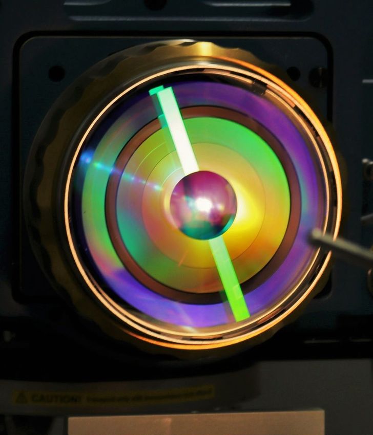
Interferometric
Asphere Testing
Customer testimonial
„Besides the remarkable perfor-
mance we reach adopting Dioptic
DFNL-type CGHs, very few com-
panies can be so collaborative in
the design phase and accurate on
delivery dates“
Massimiliano Rossi
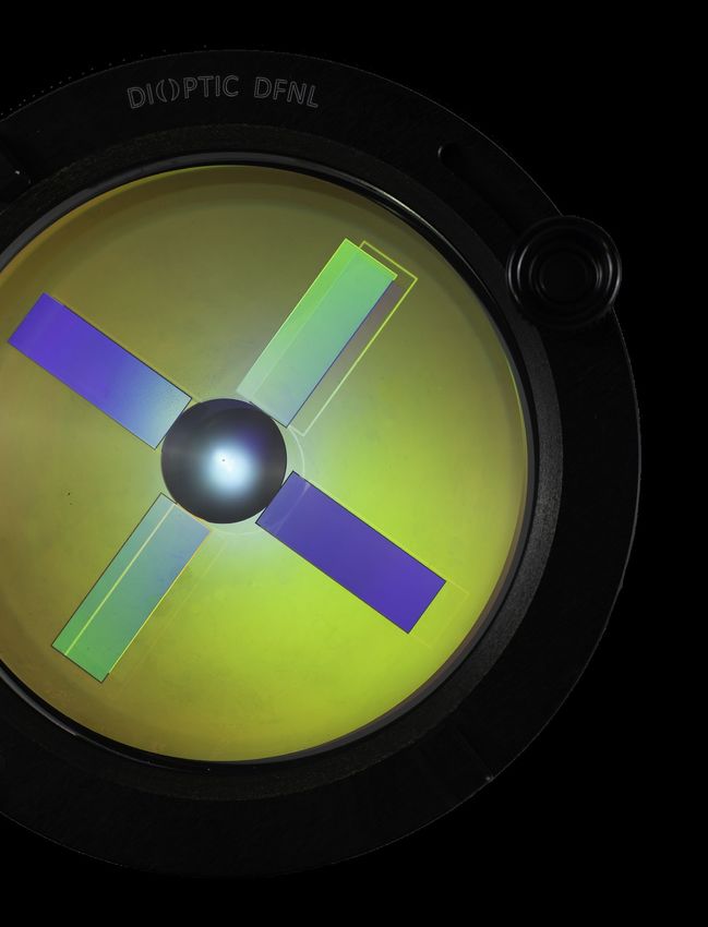
(Media Lario S.r.l.) Interferometer DFNL Surface
Surface Testing with a DFNL
DFNL with adjustment hologram CGH for free form testing 5-axis CGH Alignment System
DFNL: ASPHERIC YOUR ADVANTAGES
TRANSMISSION SPHERE
• Testing of:
• Our patented DFNLs (Diffractive Fizeau Null Lenses) • large convex surfaces
are used in the same manner as standard transmission • surfaces with large radius
spheres. DFNLs allow the testing of a wide range of non- • (Off-axis) aspheres
spherical surface forms • Cylinders
• The Fizeau principle guarantees that the set-up is free of • Free form surfaces
any disturbances resulting from the hologram substrate • Compatible with all common interferometers
• Easy adjustment of the lens under test by means of the • Fast-track manufacturing within 3 weeks possible
integrated adjustment hologram
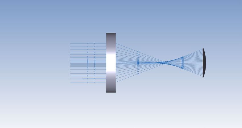
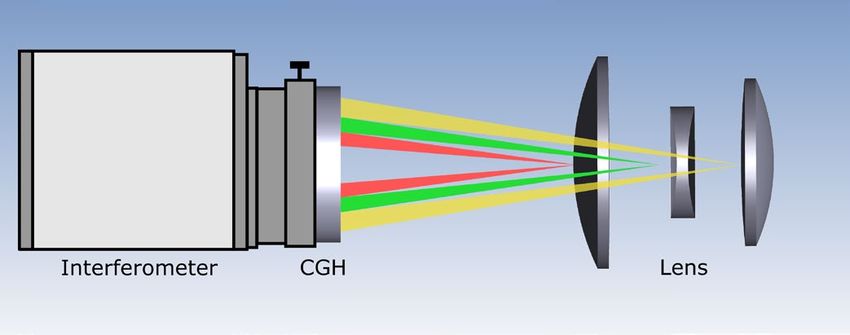
CGH: INTERFEROMETRIC TESTING OF
STRONGLY CURVED SURFACES Parameter Value
Surface type Convex & Concave
• For strongly curved surfaces computer generated holograms
220 mm (Convex)
(CGHs) are combined with a spherical transmission sphere Maximum test diameter
8m (Concave)
• Various alignment aid holograms for alignment of the
± 1.0 - ∞ (DFNL)
CGH and the test element are integrated on the CGH f/#
± 0.7 - ∞ (CGH)
substrate
Measurement accuracy λ/20 (λ/40 with calibration)
• 5-axis CGH alignment system available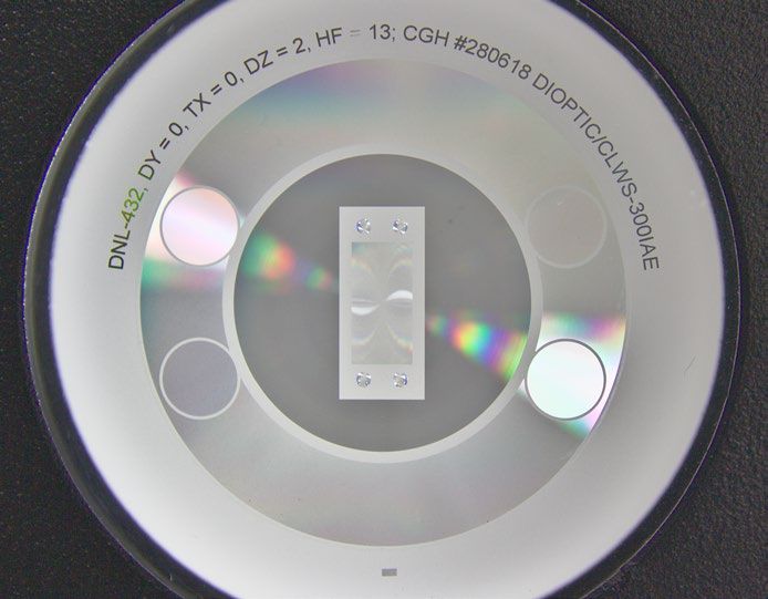
Precision Alignment
of Optical Systems

                                                                                   Alignment principle of a mirror telescope

              8 zone CGH for the alignment of the Euclid space telescope               Alignment principle of a lens system

LENS ALIGNMENT

• Ultra precise alignment of several lenses with a relative accuracy down to 1µm
• Simultaneous alignment of the lens position and tilt possible

ALIGNMENT OF MIRROR TELESCOPES                                                                    Customer testimonial

• Alignment of mirrors in a telescope with micrometer precision                          „Up to 8 lenses plus a reference
• The relative postion and tilt of the mirrors can be tested using several                beam literally „happening“ on
                                                                                         one single glass surface ... that‘s
  sub-holograms on a single substrate
                                                                                          optics designers dream world.”
                                                                                         Dr. Frank Grupp (Observatory
                                                                                               Max-Planck-Institute for
YOUR ADVANTAGES                                                                                 extraterrestrial Physics)

• Alignment of systems with extremely small alignment tolerances
• Alignment of systems with a detection spectrum far from the visible
  range (e.g. mirror telescopes)
• Alignment of systems operating in conditions that cannot be reproduced
  during the manufacturing process (e.g. temperature for space telescopes)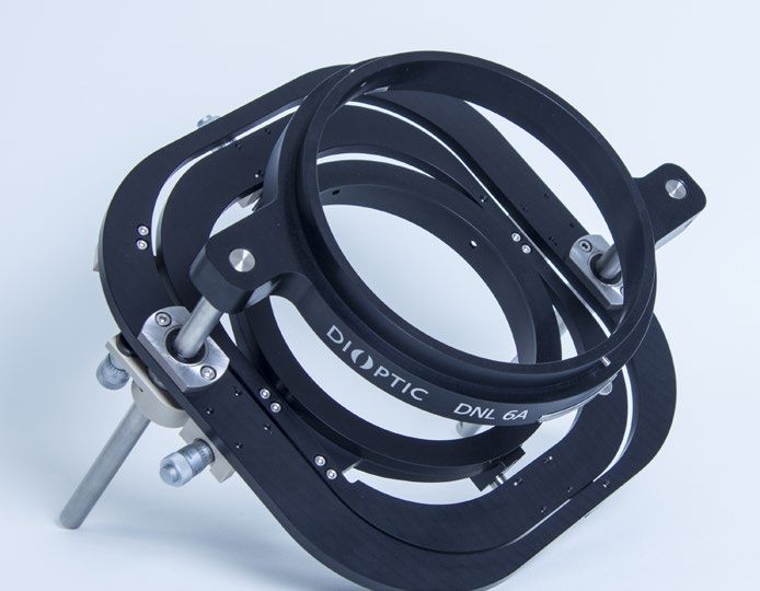
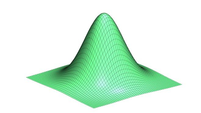
Laser Beam Shaping

                                                                                           Gaussian input beam

                                                                Circular flat top beam     Square flat top beam      Linear flat top beam
Laser beam shaper

                                                                                                                  Customer testimonial
COMPUTER GENERATED HOLOGRAMS FOR
LASER BEAM SHAPING                                                                   „Our longtime partner DIOPTIC supports us reliably
                                                                                     and with high-quality holograms for the beam path
• Generation of various intensity distributions from a laser beam:                       of the SCHWIND AMARIS excimer laser family.
                                                                                      These ensure a very reproducible beam profile and
  • Laser beam homogenization
                                                                                         a trouble-free optical beam path. The result is a
  • Structured illumination
                                                                                      Super Gaussian beam profile, which contributes to
  • Beam splitter                                                                      the particularly smooth and tissue-saving removal
  • Diffusers                                                                                         by AMARIS in laser eye surgeries.“
  • Pattern projection                                                                    Thomas Hollerbach, Project manager R&D
• Application in medical technology, automotive sector, 3D measu-                           (SCHWIND eye-tech-solutions GmbH)
  rement, product marking, counterfeiting protection and consumer
  products

YOUR ADVANTAGES

• Customer specific design, manufacturing and testing from a
  single source
• Production of individual pieces and series production possible
• Low energy loss: Up to 95% diffraction efficiency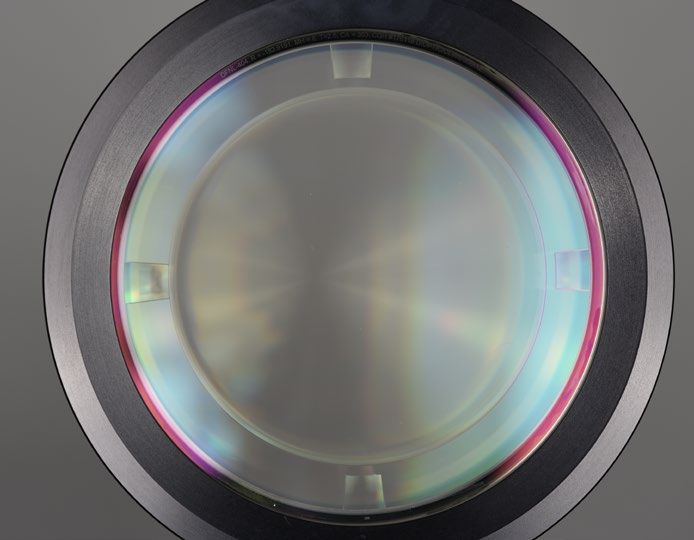
Quality management
                                                           • DIN ISO 9001:2015 certified
                                                           • Complete documentation

Industry experience                                        • Transparent results

• Compliance of industry standards
• Extensive network
• Fast project launch time

                                       Better
                                      together
                                     Advantages with DIOPTIC

Flexibility
• Quick reaction time
• Personal support
                                                  Know-how of our expert team
                                                  • Solutions on a high scientific level
                                                  • Patentable results
                                                  • Efficient and professional project handling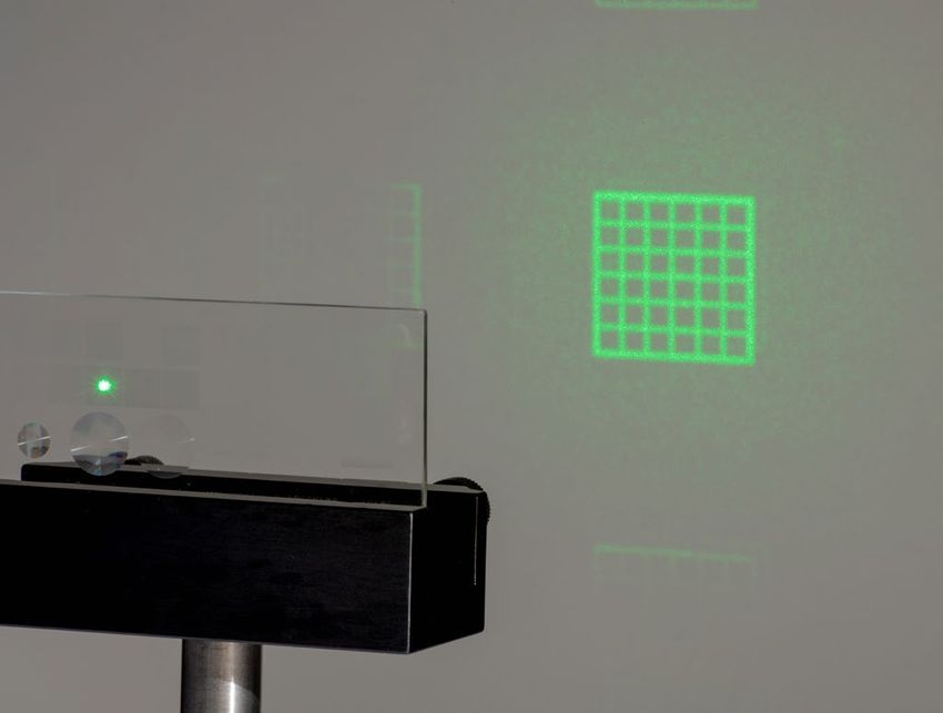
Head Office:
DIOPTIC GmbH
Bergstraße 92A
69469 Weinheim
Germany
Tel. +49 6201 65040-00
CGH@dioptic.de
www.dioptic.de

China:
Beijing OPTURN Company LTD
Room 607, Yingzhi Building
No. 49-3, Suzhoujie Street
Beijing 100080
China
Tel. +86 10 62527843
sales@opturn.com
www.opturn.com

UK:
Lambda Photometrics Ltd.
Batford Mill
Harpenden, Hertfordshire, AL5 5BZ
United Kingdom
Tel. +44 1582 764334
Ken.Middleton@Lambdaphoto.co.uk

Israel:
Lahat Technologies Ltd.
Atir Yeda St. 17
4464313 Kfar Saba
Israel
Tel. +97209 7646 200
sales@lahat.com

You can also read