Consortium For On-Board Optics Optical Connectivity Options for 400 Gbps and Higher On-Board Optics - COBO
←
→
Page content transcription
If your browser does not render page correctly, please read the page content below
Consortium For On-Board Optics Optical Connectivity Options for 400 Gbps and Higher On-Board Optics
Connectivity Options for 400G+ OBO Application Note

 COBO WORKING GROUP PARTICIPANTS
 3M Company						Oclaro
 ADVA Optical Networking SE			                 Optec Technology
 Applied Optoelectronics Inc.				Optomind
 Arista							Panduit
 Celestica						PETRA
 Ciena							Quanta
 Cisco							RANOVUS
 Credo Semiconductor					                      Reichle & De-Massari AG
 DustPhotonics Ltd.					Rosenberger
 East Point Communication Technology Co., Ltd. Samtec
 Fujikura Ltd.						Semtech
 Fujitsu Optical Components				SENKO
 Furukawa Electric					Sicoya
 GlobalFoundries					Sumitomo
 Hirose Electric (USA)					TE Connectivity
 HUBER+SUHNER AG				US Conec
 IBM Corporation					Yamaichi ElectronicsInnovium
 Inphi
 Jess-Link Products Co., Ltd.
 Lumentum
 Luxshare Precision Industry Co., Ltd.
 Mellanox
 Molex Electronic Technologies
 Microsoft

v1.1 ©March 2019                                                                              Page 2
Connectivity Options for 400G+ OBO Application Note

 CONTENTS
 1.0      Introduction......................................................................... .................................................................................1
            1.1 Scope and Purpose.....................................................................................................................................1
      1.2 Advantages of On-board Optical Modules.............................................................................................1
 2.0 Connectivity Options Between Module and Front Panel................................................................................2
      2.1 Pigtailed or Connectorized Connectivity Options................................................................................2
      2.2 Connectivity Considerations................................................................................................................... 4
 		          2.2.1 Module and Board Density.......................................................................................................4
 		                      2.2.2 Module Manufacturing and Test..............................................................................................4
 		                      2.2.3 System Assembly and Risk of Damage....................................................................................4
 		                      2.2.4 Inventory.....................................................................................................................................5
 		           2.2.5 Performance: Loss, Reflectance and Loss Variation..............................................................5
 		           2.2.6 Failure Points and Repair Process............................................................................................ 8
 		           2.2.7 Impact on Choice of Fiber Cabling Type................................................................................8
 3.0 Optical Media........................................................................................................................................................ 8
       3.1 Fiber Types..................................................................................................................................................8
 		           3.1.1 Single-mode Fiber Types.......................................................................................................... 9
 		           3.1.2 Multimode Fiber Types............................................................................................................11
 		           3.1.3 Emerging Technology: High Density Fiber Interface with Thinner Fibers...................... 12
       3.2 Fiber Handling...........................................................................................................................................12
 4.0 Fiber Reliability.....................................................................................................................................................12
       4.1 Limitations on Fiber Bending................................................................................................................. 15
       4.2 Reliability of Bent Fibers.......................................................................................................................... 15
 5.0
  Fiber Optic Connectors.......................................................................................................................................15
    5.1 Connector Types in COBO Specification.............................................................................................. 15
 		       5.1.1 MPO-12 and MPO-16 Connectors........................................................................................ 16
 		       5.1.2 Dual LC Connector.................................................................................................................. 17
 		       5.1.3 CS Connector............................................................................................................................ 18
   5.2 Alternative and Emerging Multi-fiber Connectors...............................................................................19
 		       5.2.1 Desired Improvements.............................................................................................................20
 		       5.2.2 Expanded Beam Multifiber Connector..................................................................................22
 		       5.2.3 Air Gap Multifiber Connector................................................................................................ 22
 		       5.2.4 Connector Performance...........................................................................................................23
 		       5.2.5 Multi-Fiber Connector Selection Considerations................................................................27
   5.3 Faceplate Density and Breakout..............................................................................................................27
 		       5.3.1 OBO Configuration Types.......................................................................................................27

v1.1 ©March 2019                                                                                                                                                           Page 3
Connectivity Options for 400G+ OBO Application Note

 CONTENTS
 6.0      Cleaning of Connector End Faces...................................................................................................................... 27
           6.1 Importance of Connector End Face Cleanliness...................................................................................27
           6.2 Standards for Connector End Face Cleanliness.................................................................................... 27
           6.3 Cleaning Methods..................................................................................................................................... 27
 		          6.3.1 Cleaning Types/Tools............................................................................................................. 28
 		          6.3.2 Dry Cleaning vs Wet Cleaning.............................................................................................. 29
 7.0 Connector Reliability and Performance Standards...........................................................................................31
      7.1 Service Environment Categories............................................................................................................. 31
      7.2 Single-mode Fiber – Telcordia GR-326.................................................................................................. 32
      7.3 Single-mode Multi-Fiber – Telcordia GR-1435.....................................................................................32
      7.4 Cabling for Customer Premises, ISO/IEC 11801 Series.......................................................................32
      7.5 Optical Cabling and Components, TIA-568.3.......................................................................................32
      7.6 Connector Performance Stability.............................................................................................................32
 8.0 References.............................................................................................................................................................. 34

v1.1 ©March 2019                                                                                                                                                     Page 4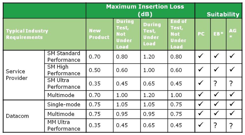
Connectivity Options for 400G+ OBO Application Note

 FIGURES
 Figure 2.1 Connectivity Options for COBO Modules................................................................................................. 8
 Figure 3.1 PIC Package with 125 µm Pitch Optical Interface....................................................................................10
 Figure 3.2 Integrated Package of LSI and Optical I/Os Having Card-Edge Connector w/125 µm Pitch Fiber Ribbon....10
 Figure 4.1 Lifetimes per Bent Fiber Meter vs Failure Probability..............................................................................13
 Figure 5.1 Physical Contact Fiber Connection and Alternatives...............................................................................16
 Figure 5.2 Endface Geometry for MT Connector (Source: US Conec)...................................................................17
 Figure 5.3 Cross-Sectional Comparison of Dust Particle and Optical Beams in Multimode PC and EB Connectors.....18
 Figure 5.4 Compatibility of Air Gap and PC Connectors.......................................................................................... 19
 Figure 6.1 Clean vs Dirty Connection.......................................................................................................................... 27
 Figure 6.2 Dry-Wet Cleaning Decision Chart............................................................................................................. 30

v1.1 ©March 2019                                                                                                                                          Page 5
Connectivity Options for 400G+ OBO Application Note

 TABLES
 Table 2-1 Comparison of OBO Connectivity Options.................................................................................................9
 Table 3-1 Maximum Bending Loss of Cabled Fiber Types.........................................................................................13
 Table 3-2 Multi-mode Fiber Categories and Relation for Modal Bandwidth and Minimum Reach....................14
 Table 7-2 Estimated Failure and Fit Rate as a Function of Bend Radius..................................................................31
 Table 7-3 Estimated Failure and Fit Rate as a Function of Proof Test......................................................................31
 Table 7-4 Estimated Failure and Fit Rate as a Function of Fiber Cladding Diameter............................................ 32

v1.1 ©March 2019                                                                                                                            Page 6
Connectivity Options for 400G+ OBO Application Note

1. INTRODUCTION
1.1 - Scope and Purpose

The Consortium for On-Board Optics (COBO) has issued its On-Board Optical Module Specification to sup-
port 400G and 800G initially, with the intent to expand to higher rates in future. [1] 400G and 800G refer
generically to multiple optical applications with aggregate bitrates of approximately 400 Gbps and 800 Gbps re-
spectively. The specification includes 400G and 800G optical connectivity between the on-board optics (OBOs)
and the front panel.

This white paper provides additional context on connectivity options, fiber choices, connector choices, han-
dling and cleaning recommendations.         It will describe the issues and options in order to inform the imple-
menter community. The options described are not exhaustive or prescriptive. Other standards are referenced as
additional useful sources of information.

The COBO specification was developed with high-density applications in mind. This whitepaper includes dis-
cussion of the concerns and proposed methods for applications with high fiber counts. It discusses connectivity
learnings based on experience with existing OBOs as well as new concepts and emerging technologies that may
be applicable to both COBO defined modules and other OBOs. The general term “OBO” will be understood to
refer to all on-board optics whether existing or compliant with the COBO specification.

1.2 - Advantages of On-board Optical Modules

For high-density applications such as data center switches, where the system is fully populated at beginning of
life, pluggability imposes undesirable and un-necessary mechanical, electrical and cooling requirements that
increase the challenges for scaling to 400 Gbps, 800 Gbps and beyond. One serious constraint is limit on ad-
ditional pluggable connectors due to faceplate size. By addressing thermal requirements, electrical interfaces,
and module design now, the COBO specification enables a roadmap for data center infrastructure to support
expected increases in traffic generated by new innovative technologies.

The density advantages of on-board optics have been recognized for decades. Existing OBO’s have been used in
high-performance computing, core routing and other applications. These have primarily been using high-count
multimode fiber. The COBO specification has been crafted with an initial goal of supporting the higher thermal
requirements of faster and larger radix switches but is intended to be generally applicable to other applications
as well.

v1.1 ©March 2019                                                                                               Page 7
Connectivity Options for 400G+ OBO Application Note

2. CONNECTIVITY OPTIONS BETWEEN MODULE AND FRONT PANEL
2.1 - Pigtailed or Connectorized Connectivity Options

The use of OBOs introduces an additional segment of fiber behind the system front panel that is not part of the
optical transmission path when using front-panel pluggable modules. The COBO specification has borrowed
the term PMD (Physical Medium Dependent) from IEEE and uses it in an additional sense to refer to the
electro-optical package mounted to the system circuit board without the fiber necessary to take the signal to
and from the card edge. The IEEE and COBO transceiver definitions encompass the PMD plus the additional
cabling to the card edge.

This section discusses the issues that should be considered when choosing between options to implement the
cabling between PMD and the card edge. Table 2-1 summarizes each type along with advantages and disadvan-
tages. As shown in Figure 2-1, the two connectivity options for this additional segment are:

 •      Pigtailed: For existing OBOs, this approach is now commonly used. There is no extra connection point
        between PMD and MDI although there is a length of fiber which is connectorized at one end.
•       Connectorized: This approach uses a patchcord with connectors at both ends. The PMD will require a
        receptacle and retention device to mate to the patchcord.

In principal, a pigtailed but not connectorized module could be spliced to a single-ended patchcord with a
connector. However, splicing at the time of host system assembly has significant disadvantages compared to
either the pigtailed or connectorized options. These disadvantages include size and cost, skill set at the contract
manufacturer and assembly time.

                               FIGURE 2.1: CONNECTIVITY OPTIONS FOR COBO MODULES

v1.1 ©March 2019                                                                                               Page 8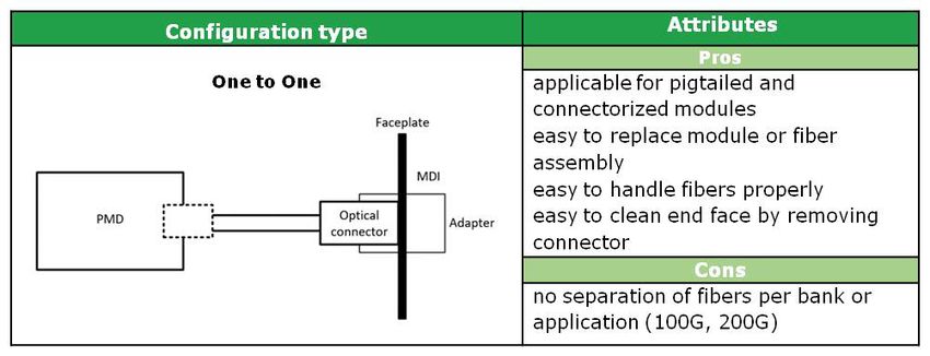
Connectivity Options for 400G+ OBO Application Note

These options and the considerations discussed below apply in all cases independent of whether the fiber is
single-mode or multimode. They also apply independent of fiber count. The COBO specification encompasses
cases where there are a small number of fibers per OBO (e.g. two fibers for a duplex PMD type) and where there
are multiple fibers per OBO (e.g. 32 fibers for an 800G parallel fiber PMD). The MDI (Medium Dependent
Interface) is always defined at the faceplate for all connectivity options.

This definition of the MDI from the COBO specification [1, p. 46] is aligned with IEEE Ethernet standards defi-
nition for the MDI [2]. The end-user of the system simply sees an MDI interface at the faceplate regardless of
COBO connectivity type, and indeed regardless of whether a COBO or pluggable module is used.

Note that the end of the fiber at the COBO PMD is not considered a standard-defined connection point but is
considered internal to the COBO implementation. This is true for any of the connectivity options. The output
power and receiver sensitivity of the OBO is specified at the MDI even for a connectorized COBO module.

Table 2-1 below shows a comparison of connectivity types for OBO. The comparisons here are relative only and
applicable for module and system manufacturers. The issues are discussed in more detail below in Section 2.2
including different impacts on module and system manufacturers.

                                             Variable                   Pigtailed    Connectorized
                            Module and board density                    Higher           Lower
                            Ease of manufacturing and test              Lower            Higher
                            Control of loss variation and reflectance   Higher           Lower
                            Ease of system assembly                     Lower            Higher
                            Ease of repair                              Lower            Higher
                                     TABLE 2-1 COMPARISON OF OBO CONNECTIVITY OPTIONS

2.2 - Connectivity Considerations

This section expands on the discussion of how connectivity options affect the lifecycle of a COBO system from
design and performance through manufacturing and supply chain to repair.

        2.2.1      Environmental, Power and Size Targets for a Reference Application

In all cases, the design of the host system needs to allow space for management of the fiber between PMD and
MDI. See Section 4.0 for a discussion of allowable fiber bend dimensions that govern this design. The connec-
torized option also requires additional space so the connector can be inserted (and removed as necessary for
repair). Retention structures for the connector on the PMD will protrude from the front of the PMD module.

v1.1 ©March 2019                                                                                                        Page 9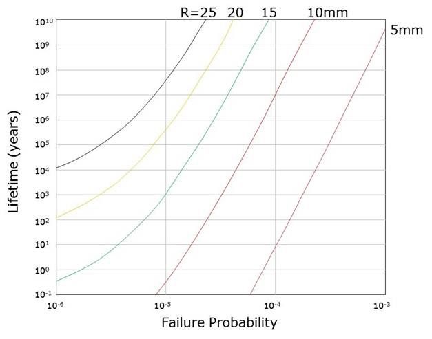
Connectivity Options for 400G+ OBO Application Note

        2.2.1      Environmental, Power and Size Targets for a Reference Application

The COBO specification was developed with high-density systems in mind. It is highly likely that there will be
multiple rows of COBO modules on a host system board, with different lengths of fiber required to reach the
front panel. With pigtailed OBOs, module vendors likely will need to prepare multiple product variants with
different lengths of fiber pigtails or terminate to order. Connectorized OBO manufacturing is streamlined to a
single product variant independent of the fiber assembly and length.

        2.2.3      System Assembly and Risk of Damage

A major advantage of the connectorized option is simplification of system assembly. The modules can be placed
and electrically connected to the host board without fiber. The fiber jumpers can be added in a separate step.
The more complex process for pigtailed OBOs also increases the risk of damage to the fragile fibers. Handling
both at the same time as in the case of pigtailed modules is complicated. Fiber management design is also im-
pacted by the presence of fiber pigtails when placing additional modules.

A connectorized OBO type adds another fiber interface that needs to be cleaned. See section 6.0 for a descrip-
tion of cleaning practices. The procedure and equipment are the same as needed for the front-panel connection,
so the main impact is to increase the time needed for this manufacturing step. This additional interface has a
risk of damage if contaminated.

        2.2.4      Inventory

Per section 2.2.2, pigtailed OBOs may vary by length of pigtail. A contract manufacturer responsible for system
assembly would then have to stock these multiple part numbers. For connectorized or spliced OBOs, the inven-
tory impact is limited to stocking multiple lengths of the passive jumpers. A contract manufacturer may wish to
use a preferred connector and jumper supplier independent of their choice of OBO supplier.

        2.2.5      Performance: Loss, Reflectance and Loss Variation

Any connection point where one fiber mates to another fiber incurs insertion loss (IL) and return loss/reflec-
tance (RL). IL is the amount of optical signal lost at the connection point; RL is the ratio of the optical power
reflected back toward its source. Performance in a fiber-optic network depends on assuring that losses for the
entire link are kept within tolerable levels. Typical IL and RL values for different grades of connectors are dis-
cussed in Section 5.2.4.

v1.1 ©March 2019                                                                                              Page 10
Connectivity Options for 400G+ OBO Application Note
Connectorized OBOs have an extra connection point compared to pigtailed OBOs so it may seem that they
would have more loss and therefore lower performance. In reality, direct comparisons are more complex and
also vary by implementation even within the same type of connectivity.
While it is likely that the connector at the PMD will incur a few tenths dB of loss, this loss does not impact link
performance. Consider that there is a finite and unknown coupling loss within either an OBO PMD to either
a pigtail or the mating connector receptacle. There are similarly possible losses within a front-panel pluggable
transceiver between internal optics and the connector receptacle. The connection loss at the PMD has the same
impact. The external link performance is assured as long as the transmitter power and receiver sensitivity meet
specifications at the MDI.
Note that the main difference between connectivity options is on the variability of the loss, which is greater for
the connectorized version. The module manufacturing test will use a temporary connection with a different
jumper than the one that will be installed during system assembly. The splice pigtail may also have slightly
different loss than in module test. Therefore, it is likely that module manufacturers will need slightly more
manufacturing margin to assure compliance at the MDI in case the assembled loss is greater. System vendors
and their contract manufacturers can specify higher grades of connectors both on the PMD and the jumper to
minimize loss variation.
The additional connector at the PMD is an additional reflectance point. Splice reflection is typically insignifi-
cant. Reflections back into a transmitter may affect laser performance. Particularly at high speeds, multi-path
interference may create link penalties. The amount of this reflectance and reflectance tolerance depends on
implementation detail. It also depends on optical link type.
2.2.6 Failure Points and Repair Process
Fault location may be simpler with a pigtailed OBO since there are fewer possible points of failure are limited to
the PMD, the fiber and the front-panel connector. A connectorized OBO adds the risk of risk to damage to the
PMD connector interface particularly due to contamination or mishandling during assembly. A spliced pigtail
adds the splice point as a potential failure point as well has more fiber handling during the splicing process.
However, repair may be simpler for a connectorized OBO if the failure is confined to the fiber. If a replacement
of the jumper suffices, the repair may be done at the contract manufacturer or even in the field. Repair of a pig-
tailed module requires demounting the entire module and sending it back to the module manufacturer. Repair
of a connectorized module would also require demounting and repair by the manufacturer if the failure is in the
PMD including the mating receptacle.
v1.1 ©March 2019 Page 11Connectivity Options for 400G+ OBO Application Note
The pigtail may be more difficult to remove than a connectorized jumper. Depending on fiber routing, this re-
moval may have greater risk of damage to other fibers. Removal of a splice pigtail is even more difficult due to
the presence of the splice protector.
2.2.7 Impact on Choice of Fiber Cabling Type
As already stated above, the fiber may be single-mode or multimode, and may range in fiber count per OBO.
Multifiber cable and ribbon fiber can be used as well; loose tube multifiber cables are more difficult to splice.
Connectorized or pigtailed OBO’s could be used with a planar multi-fiber flex circuit for easier fiber routing for
many OBO modules. Such multi-fiber flex planes may reduce the hindrance of the airflow compared to multi-
ple cables or ribbons within the housing.
v1.1 ©March 2019 Page 12Connectivity Options for 400G+ OBO Application Note
3. OPTICAL MEDIA
3.1 Fiber Types
The optical media used for the pigtail of a COBO module are composed of either single-mode or multimode
fiber. Manufactures can choose the types of fiber according to their optical engine operational function. In gen-
eral, multimode fiber is to support a VCSEL based optical engine, whereas single-mode fiber supports longer
wavelength single-mode light sources.
3.1.1 Single-mode Fiber Types
There are several types of single-mode fiber defined by IEC 60793-2-50 [3] Cabled single-mode fiber types are
defined in ITU-T recommendations [4] [5]. For pigtail connectivity users should consider two general types
of fiber: standard single-mode fiber (IEC: B-652 / ITU-T: G.652 types) and bend insensitive fiber (IEC: B-657
/ ITU-T: G.657 types). Although standard single-mode fiber is used for pigtail applications, users may require
bend insensitive fiber to achieve tighter bends in more difficult fiber routing architectures. It should be noted
these standards are regularly reviewed and renewed. It is the user’s responsibility to find the latest versions. See
the end of References section for some useful links.
The macro bending loss is an important factor when considering the section of fiber for the pigtail fiber of a
COBO module. Table 3 1 summarizes the comparison of the specified maximum macro bending loss for each
fiber type. From top to bottom, the bending loss decreases significantly.
Macro Bending Loss (dB/Turn)
Wavelength R R R R R
Fiber Category Sub Category
(nm) 5 mm 7.5 mm 10 mm 15 mm 30 mm
G.652 A/B/C/D/E 1625 0.001
G.657 1550 0.075 0.025
A1
1625 1.500 0.100
A2/B2 1550 0.500 0.100 0.003
1625 1.000 0.200 0.010
1550 0.150 0.080 0.030
B3
1625 0.450 0.250 0.100
TABLE 3-1: MAXIMUM BENDING LOSS OF CABLED FIBER TYPES
v1.1 ©March 2019 Page 13Connectivity Options for 400G+ OBO Application Note
3.1.2 Multimode Fiber Types
Multimode fiber is characterized by core diameters larger than those of single-mode fiber. As a result, it has
larger alignment tolerances and easier optical alignment assembly. Multimode fiber is much less sensitive to
macrobending loss than single-mode fiber due to a higher index difference between core and cladding. The
reach of multimode fiber is limited compared to the reach of single-mode fiber due to modal delay difference
that deteriorates the optical signal quality. The reach and bandwidth can be traded off in application. There are
multiple types of multimode fiber with different reach-bandwidth specifications and target applications.
Data center applications typically use multimode graded-index 50 µm fibers sub-category A1-OM3 to A1-OM5
specified in IEC 60793-2-10 [6]. The standard specifies the minimum modal bandwidth for several wave-
lengths and supports the minimum reach of Ethernet variants as defined in ISO/IEC 11801-1 [7] . Below is a
table showing the multimode categories versus modal bandwidth and reach.
M I N I M U M R E A C H ( m )
Core/Cladding Min Modal Bandwidth @ 10GbE 40GbE 40GbE 100GbE
Category
Diameter (μm) 850 / 953 / 1300nm (MHz-km) 10GBASE-SR 40GBASE-SWDM4 40GBASE-SR4 100GBASE-SR10
OM1 62.5/125 200 / - / 500 33
Not Supported
OM2 50/125 500 / - / 500 82
OM3 50/125 1500 / - / 500 300 240 100 100
OM4 50/125 3500 / - / 500 400 350 150 150
OM5 50/125 3500 / 1850 / 500 400 350 150 150
TABLE 3-2: MULTI-MODE FIBER CATAGORIES AND RELATION FOR MODAL BANDWIDTH AND MINIMUM REACH [7]
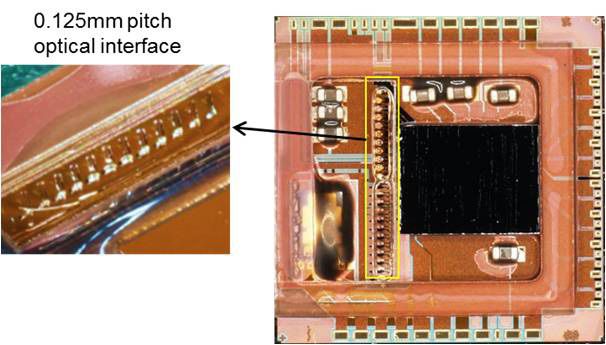
3.1.3 Emerging Technology: High Density Fiber Interface with Thinner Fibers
The COBO specification is driven by a need for greater density. It takes advantage of increasing densities of the
optical chips inside. In response to pressure to improve the fiber density to better match the chip density, there
is a new project in IEC TC86 JWG9 (Joint Working Group 9) working to standardize to a finer fiber pitch. The
new “half-pitch” interface proposal describes an array pitch of 125 µm, down from today’s typical 250 µm. The
new proposal applies to both multimode and single-mode, using fibers with 80 µm cladding outer diameter in
a single row of 32 channels.
v1.1 ©March 2019 Page 14Connectivity Options for 400G+ OBO Application Note
The proposed standard is expected to find use in high density board-to-board and optical backplane intercon-
nects, optical print circuit boards, optical backplanes, PIC (Photonic Integrated Circuit) packages and package
level integration of LSI and optical engines. Technical challenges that increase with reduced pitch include han-
dling and ribbonizing of the smaller fibers, controlling manufacturing of precision holes and greater accuracy
in assembly.
Another challenge is that a half-pitch interface of 125 µm is not compatible to the existing installed and widely
manufactured cable assemblies where a pitch of 250 µm is used. Jumper assemblies with a pitch of 125 µm on
one side and of 250 µm on second side are required to connect to installed cabling.
FIGURE 3-1 EXAMPLE OF PIC PACKAGE WITH 125 µM PITCH OPTICAL INTERFACE
FIGURE 3-2 EXAMPLE OF INTEGRATED PACKAGE OF LSI AND OPTICAL I/OS HAVING
CARD-EDGE CONNECTOR WITH 125 µM PITCH FIBER RIBBON
v1.1 ©March 2019 Page 15Connectivity Options for 400G+ OBO Application Note
3.2 Fiber Handling
Optical fiber is made of glass and therefore should be handled carefully for integrity (no fiber damage or break-
age) and user safety. The fiber coating, usually made of acrylate, mechanically protects the glass fiber and should
not be damaged or removed unnecessarily. As long as the fiber coating (typically 250 µm) is protecting the
glass fiber, the fiber is resistant to breaking under bending. If the fiber coating is removed for some assembly
step, the fiber becomes significantly more brittle and extra care needs to be taken. Users need to understand the
risks of fiber handling and follow the guidance below:
• Do not crush fibers as it may cause fiber damage or breakage.
• Do not apply bend and/or load more than the value of the fiber specification.
• Treat fiber carefully to prevent unnecessary breakage. Although fiber is screened for tension proof test,
it can still break easily.
• Proper protection should be used (e.g. safety glasses) when handling bare fiber. Broken fiber pieces
can be dangerous. They are extremely small and once inside the human body they are very hard to
identify. It may cause human body injury.
• Avoid eye or skin exposure to direct radiation from the fiber or connector end(s) as this may result in
injury. Laser light used in data communications and telecommunication is not visible to the naked eye.
Check that the laser power is turned off completely or the fiber is disconnected from any laser source
before inspection of the fiber end.
v1.1 ©March 2019 Page 16Connectivity Options for 400G+ OBO Application Note
4. FIBER RELIABILITY
4.1 Limitations on Fiber Bending
The mechanical fiber reliability and failure probability are important factors to consider in COBO module use
cases. Additionally, the bend loss has to be considered as well. The steady increase of switch ASIC bandwidth
drives growth in the numbers of transceivers on a host board. Boards with a high density of on-board modules
leave only narrow spaces and create challenges for fiber routing, notably the need for tight bends. Tight bend-
ing increases the probability of fiber breakage. Board design requires care to balance the considerations for
on-board module layout, macro bending loss and fiber bend failure probabilities to guarantee COBO module
operability, lifetime and reliability.
This chapter discusses fiber reliability under a bent condition. Macrobending loss for single-mode fiber is de-
scribed in 3.1.1.
4.2 Reliability of Bent Fibers
Continual bending of an optical fiber will result in fatigue in the glass fiber due to the increased residual stress
inside of the fiber cross section. During the fiber manufacturing process, the optical fiber is subjected to a proof
test by applying a tensile stress in the longitudinal direction for a controlled period of time. This test screens
out any faulty portion along the entire length of optical fiber. For example, proof stress level of 1% (measured as
elongation under applied tensile stress; for 125 µm diameter fiber, 1 % corresponds to 0.69 GPa) is the screening
condition used for conventional terrestrial optical fiber.
Based on this screening process, the fiber lifetime estimation adopted by IEC/TR 62048 [4] is used to assure
mechanical reliability. In this document, the lifetime tf is defined as where a is bending stress, p is proof
stress, tp is proof time, P is failure probability, L is the bent length, m is the Weibull form factor and n is a fatigue
coefficient.
FIGURE 4-1: EQUATION
v1.1 ©March 2019 Page 17Connectivity Options for 400G+ OBO Application Note
FIGURE 4 1 LIFETIMES PER BENT FIBER METER VS FAILURE PROBABILITY
Below are estimations using this formula and assuming parameter values of n=20, m=3, Np=1.0E-6 [ /m] and
tp =1 sec.
Below is the failure probability difference calculated result assuming the proof stress is applied by 1 % with a
standard fiber cladding diameter of 125 µm. These results show that a smaller bend radius and long-term con-
dition result in a worse failure probability, whereas the best probability is estimated to be larger bend radius and
shorter-term condition.
It is important to note that Table 4-1 shows failure probability over a meter which is bent continuously at the
bend radius specified. For typical OBO module applications, the fiber will only be bent at these radii for frac-
tions of a turn to several turns. Probabilities shown do not account for the fact that a smaller bend radius turn
occurs over a shorter length, e.g. a 30mm turn requires 0.18 m of fiber, but a 5 mm turn requires 0.03 m of fiber.
Bend Radius Failure probability* (m¯1)
(mm) 20 years 5 years 3 years
30 2.5 x 10¯12 6.24 x 10¯13 3.74 x 10¯13
15 5.99 x 10¯7 3.04 x 10¯7 2.24 x 10¯7
7.5 1.49 x 10¯5 1.17 x 10¯5 1.06 x 10¯5
5 6.06 x 10¯5 4.79 x 10¯5 4.39 x 10¯5
TABLE 4-1 FAILURE PROBABILITY VS BEND RADIUS AND TIME
* For fibers with proof test 125 μm fiber cladding diameter
v1.1 ©March 2019 Page 18Connectivity Options for 400G+ OBO Application Note
Below is the calculated bend radius failure probability difference by applied proof stress ranging from 1 %
through 2 %, assuming 5 years span with a standard fiber cladding diameter of 125 µm. As can be seen, the fiber
applied a higher proof stress gives lower failure probability because the higher proof stress can eliminate the
weak portion of the fiber during its manufacturing process.
Bend Radius Failure probability* (m¯1)
(mm) 1% 1.5% 2%
30 6.24 x 10¯13 - -
15 3.04 x 10¯7 1.97 x 10¯10 6.24 x 10¯13
7.5 1.17 x 10¯5 2.28 x 10¯6 3.04 x 10¯7
5 4.79 x 10¯5 1.17 x 10¯5 3.85 x 10¯6
TABLE 4-2 IMPROVEMENT OF FIBER RELIABILITY UNDER BENDING BY PROOF STRESS
* For fibers with 25 μm fiber cladding diameter, over five years
Below is the calculated failure probability using different fiber cladding diameters. Compared to the standard
fiber cladding diameter of 125 µm, fibers with smaller cross-sections have less residual stress when bent and
therefore lower failure probability.
Bend Radius Failure probability* (m¯1)
(mm) 125 µm 100 µm 80 µm
30 6.24 x 10¯13 7.22 x 10¯15 -
15 3.04 x 10¯7 7.40 x 10¯9 8.69 x 10¯11
7.5 1.17 x 10¯5 5.02 x 10¯6 1.86 x 10¯6
5 4.79 x 10¯5 2.22 x 10¯5 1.00 x 10¯5
TABLE 4-3 DEPENDENCE OF FIBER RELIABILITY ON FIBER CLADDING DIAMETER
* For fibers with 1% proof test, over five years
v1.1 ©March 2019 Page 19Connectivity Options for 400G+ OBO Application Note
5. FIBER OPTIC CONNECTORS
5.1 Connector Types in COBO Specification
There are three connector types listed in the COBO specification for fiber optic connectivity at the MDI. The
best choice of connector type is primarily dependent on fiber count. In general, PMDs that use more than two
fibers are best served by using a multi-fiber connector. Other connector types with similar fiber count may be
considered as long as they meet the lane assignment requirements that are defined in the COBO specification.
All the existing connectors described in this section (both single and multi-fiber) share the same attributes at
the fiber level. They differ in the mechanics to assure fiber alignment, but all require physical contact of the
individual fibers. The next section describes alternatives which do not share this requirement for physical con-
tact. Physical contact (PC) connectors represent the vast majority of fiber optic deployed solutions today. It is a
mature technology with a wide range of non-proprietary solutions and interoperable vendors. PC also enables
the best possible optical performance for most applications, although it can require considerable preparation
and care to maintain yields at the factory and deploy in the field. To help minimize these tradeoffs, the industry
has adopted standardized processes to polish, clean, and inspect PC connectors.
5.1.1 MPO-12 and MPO-16 Connectors
Single and dual-row MPO-12 and MPO-16 are specified for MDI connections and can contain up to 32 fibers
per connector. TIA-604-5 [8] , IEC 61754-7-1 [9], and IEC 61754-7-2 [10] specify the mechanical intermate-
ability requirements of the plug, adapter and receptacle for the MPO-12 connectors. The optical plug, adapter
and receptacle for the MPO-16 connector is defined by TIA-604-18 [11], IEC 61754-7-3 [12] and IEC 61754-
7-4 [13].
To ensure proper orientation at the MDI between the OBO and the patch cord, both MPO-12 and MPO-16
OBOs use aligned keys. For both connector types, this means the optical connector is orientated such that the
keying feature of the MPO receptacle is towards the top of the OBO.
5.1.2 Dual LC Connector
The Dual LC optical patch cord and OBO receptacle, which is specified in TIA-604-10 [14] and IEC 61754-20
[15] , can also be used in COBO designs. It is two individual single-fiber connectors often ganged together into
a dual (or “duplex”) configuration.
v1.1 ©March 2019 Page 20Connectivity Options for 400G+ OBO Application Note
5.1.3 CS Connector
The CS optical patch connector and receptacle is a new PC-type connector. The first version of this connector
specification [16] was issued in late 2017 by the QSFP-DD MSA. CS will be specified in TIA-604-19. At the
time of this white paper, TIA was in the process of being written with a 2019 target publish timeframe. CS is a
two-fiber connector, which can be paired at the OBO for a total of four fibers.
5.2 Alternative and Emerging Multi-fiber Connectors
Alternatives to PC connectors include expanded beam (EB). Multimode multifiber EB connectors have been
used in service provider and high performance computing applications for over a decade. Other EB variants
are used extensively in the military/aerospace industry. The COBO specification is forward-looking and tar-
gets expansion to future applications. In recent years, the fiber optic connector industry has put effort into
addressing some desires for improvement. Additional emerging technologies that may be particularly relevant
to multifiber communications including COBO-compliant designs include single-mode EB and single-mode
or multimode Air Gap (AG). These are currently proprietary to individual connector manufacturers, but may
offer positive tradeoffs for certain applications. Figure 5-1 illustrates the difference between PC and expanded
beam (EB) and Air Gap (AG) connectors.
FIGURE 5-1 PHYSICAL CONTACT FIBER CONNECTION AND ALTERNATIVES
Section 5.2.1 describes the issues they seek to address. Sections 5.2.2 and 5.2.3 discuss in detail the EB and AG
approaches and the improvements they offer. Section 5.2.4 describes some performance criteria that should be
considered and finally section 5.2.5 and Table 5 2 summarize the comparison between PC, EB and AG. Note
that single-mode and multimode applications have different sensitivities. Care should be taken to make the
comparison for the appropriate type of connector for the user’s application.
v1.1 ©March 2019 Page 21Connectivity Options for 400G+ OBO Application Note
5.2.1 Desired Improvements
Lower connector spring force may be a desirable improvement for applications such as multi-fiber connectors
with greater than thirty-two fibers per port and blind mate mid-plane/backplane connections, especially those
with multiple ports (e.g. ganged connectors).
The fibers in PC connectors are precision-aligned, polished to a smooth finish (see Figure 5-2), and then mated
with enough force to planarize both endfaces. The Endface Geometry requirements are specified in standard
EN 50377-15-1:2011 [17] and IEC 61755-3 family of standards [18] [19] [20]. This eliminates any air gaps be-
tween fibers, and in the ideal case, creates a continuous propagating media where light can travel as if inside a
single optical glass fiber. The challenge is that the force required is roughly proportional to the number of fibers
(at a rate of about 1 N per fiber).
FIGURE 5-2 ENDFACE GEOMETRY FOR MT CONNECTOR (SOURCE: US CONEC)
Another area where improvement is sought is the impact of debris on the connector endface. PC connectors re-
quire a clean endface. Debris can occlude light but furthermore lack of proper physical contact can also degrade
insertion loss or back reflectance performance. In most installations, PC connectors are inspected and cleaned
to ensure proper physical contact and that no permanent damage is induced onto the endface.
In the case of multi-fiber connectors, this issue gets compounded by the laws of probability. For some instal-
lation environments, an alternative connector solution may be desired. Examples include installation sites not
equipped to perform adequate cleaning/inspection, harsh environment installations, and mid-plane / back-
plane connections where accessibility to cleaning may be limited (especially in the field).
v1.1 ©March 2019 Page 22Connectivity Options for 400G+ OBO Application Note
5.2.2 Expanded Beam Multifiber Connector
One possible emerging technology is expanded beam (EB) connectors. Millions of multimode EB connectors
(not including lensed receptacles inside pluggable transceivers) have been deployed over the past decade. While
this is a mature industry, it is still largely proprietary and their volumes are still dwarfed by PC connectors. At
the time of this white paper, single-mode EB connectors are emerging as well. Per their name, EB connectors
have a larger light beam in the region between connectors than in the fibers. By doing so, the portion of light
blocked by dust particles is smaller than in the conventional physical contact case, and so is the degradation of
the signal itself.
EB solutions do not require physical contact between the fibers and are insensitive to variation in the location of
the light beam in all three axes. Connector insensitivity in the x and y-axes (i.e. orthogonal to the direction of
the light) can be helpful in applications with high vibration or side load requirements. Connector insensitivity
in the z-axis (i.e. parallel to the direction of the light) can be helpful in sites with significant debris. EB connec-
tors also eliminate the need to polish fibers and measure endface geometry.
The reduced effects of dust are sketched in Figure 5 3 where the cross-sectional area of a fiber in a PC connector
is compared to an EB (16 times larger beam area). The same dust particle is overlaid on both cross-sections,
intuitively showing how the same particle blocks a significant portion of the optical signal in the multimode
50 µm PC case, while it blocks an insignificant portion of the EB signal. The enhanced insensitivity to debris is
proportional to the area of the beam.
FIGURE 5-3 CROSS-SECTIONAL COMPARISON OF DUST PARTICLE AND
OPTICAL BEAMS IN MULTIMODE PC AND EB CONNECTORS
v1.1 ©March 2019 Page 23Connectivity Options for 400G+ OBO Application Note
Another advantage of EB connectors is lower mating force (< 3 N total). Because it does not require a PC
connection, the EB connector mating force is independent of the fiber count per port. This enables the use of
multi-fiber connectors in applications where board-level components or connections could get damaged by
larger mating forces. For the same reason, expanded beam technology also reduces tooling or mechanical fea-
tures that might be required to latch/engage high fiber count and/or ganged connectors. Additionally, a lower
mating force generally results in less debris generation during mate-demate cycles, which can greatly reduce the
need to clean the connector endface. As mentioned in 5.2.1, this can result in less debris generation between
mating cycles, which can enable high density ganged connector designs. It can also significantly reduce instal-
lation time in the field.
The technical tradeoff with EB connectors is that they typically exhibit worse insertion loss and return loss per-
formance compared to PC. Manufacturers are actively working to improve EB performance with the goal to
achieve similar performance as PC.
5.2.3 Air Gap Multifiber Connector
Another possible emerging technology is air gap (AG) connectors. It does not require PC between fibers and
intentionally applies a controlled micron (µm) air gap between the fiber endfaces of mated connectors. AG
connectors can use an angled endface option to achieve low optical reflectance performance similar to that of
angled physical contact (APC) connectors. AG connectors can achieve low insertion loss due to the small gap
distance applied between mated connectors.
FIGURE 5-4 COMPATIBILITY OF AIR GAP AND PC CONNECTORS
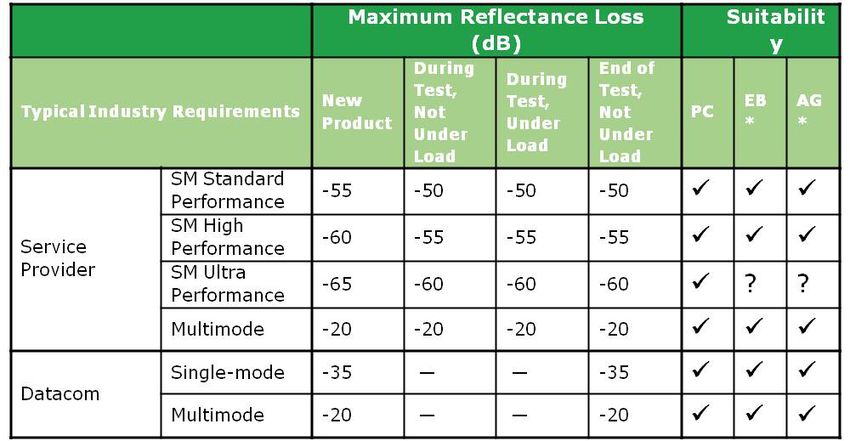
v1.1 ©March 2019 Page 24Connectivity Options for 400G+ OBO Application Note AG connectors have a low mating force (3 N) requirement independent of the fiber count per port. As men- tioned in Section 5.2.1, this can result in less debris generation between mating cycles, which can enable high density ganged connector designs. The AG connector can mate to either another AG connector or to a standard PC connector as shown in Figure 5 4. For AG compatibility with conventional PC type connectors, the AG side should have the appropriate gap, polarity and compatible connector type. The optical performance for AG to PC is proprietary to the vendor. The technical tradeoff is that the light beam for the AG connector is about the same diameter as for PC connec- tor type. Therefore, the loss of AG connector is more sensitive to dust than EB. Compared to PC however, the AG connector should be easier to clean since debris is less likely to be pressed between the fibers. 5.2.4 Connector Performance Note that designs must account for the worst-case loss that can be anticipated for any given mated pair solution. Worst Case Insertion Loss = Specified Insertion Loss (Max) + Change in loss from service conditions (Max) Service conditions that should be specified include: • Frequency of cleaning, test and inspection. • Number of mate-demate cycles between cleaning/inspection • Thermal Cycles (number and operating temperature range) • Aging (which is simulated by accelerated thermal and humidity exposure) • Dust conditions. Specifiers should consider using existing industry standards to define use qualification requirements, including ANSI/TIA-568.3-D [21], GR-1435-CORE [22] or GR-326-CORE [23]. These standards serve as a good refer- ence point, even if the user or Original Equipment Manufacturer chooses to relax or tighten the specifications for their specific application or product. See also Section 7.0 for relevant standards specifying tests, recom- mended performance criteria as well as reliability tests for connectors. These tables reflect a general summary of standards requirements. Users should consult the standards them- selves for specific details about qualification testing and application of standards. There exist multiple grades of optical performance, with some typical criteria levels shown in Table 5-1. v1.1 ©March 2019 Page 25
Connectivity Options for 400G+ OBO Application Note

                          TABLE 5-1 EXAMPLE MODULE DESIGN USING FULLY INTEGRATED OPTICAL SUBASSEMBLY

High optical reflectance can cause optical transmission devices like lasers to operate incorrectly. The specified
maximum reflectance for the connector should be less than that required by the optical transmission device. It
should be noted that legacy analog broadband requirements have driven the telecom industry to standardize on
max reflectance of -55 dB, but many transmission devices will perform suitably at higher reflectance.

        5.2.5      Multi-Fiber Connector Selection Considerations

Assuming that the optical performance of one of these alternative connector types is suitable for the application,
the decision to use an alternative connector type will be primarily driven by the desire to reduce mating force
or cleaning requirements. Table 5-2 provides a summary of the how the alternative connection types compare
with physical contact connections.
v1.1 ©March 2019                                                                                                 Page 26
Connectivity Options for 400G+ OBO Application Note
PC EB AG
Criteria
MM: Mature (10+ years)
Technology maturity Mature (20+ years)
Millions deployed Emerging
(as of 2019) Billions deployed
SM: Emerging
Physical contact of mated fibers Yes No No
Optical interface specified in standards Yes No No
Enables low force ganged connectors No Yes Yes
10 N for 4f to 16f* ferrule ≤3 N per ferrule and indpendent of
Mating force
20 N to 16f* to 32f ferrule fiber count
Connector debris created by high
number of mate / de-mate cycles High Low Low
Sensitivity to displacement in z-axis High Low Medium
Supply chain options MM: Medium
High SM: Low Low
MM Beam diameter Approximately 50µm Vendor Defined Approximately 50µm
MM sensitivity to dust in the optical path High Lowest Medium
SM Beam diameter Approximately 50µm Vendor Defined Approximately 50µm
SM sensitivity to dust in the optical path Highest Low High
Cleaning for dust particles Hardest Easiest Easiest
Cleaning type for dust particle Tape and/or wet Canister Air Blow, Tape, Wet
Inspection and cleaning cycle between MM: Medium
mattings for random dust in a controlled Before every matting As needed
environment SM: Low
TABLE 5-2 SUMMARY OF CONNECTOR TYPES
*At the time of publication of this white paper, the TIA standard specifies 20N for 16f PC ferrules while the IEC is unpublished.
5.3 Faceplate Density and Breakout
COBO offers several options for faceplate connectors that provide the ability to design the faceplate for easier
breakout or for faceplate density.
There are several factors that are important in the selection of the connector. The first factor is the COBO engine
type, which is specified as either an independent 400G engine, dual 400G independent engines or a 2x 400G
integrated engine. The choice of the engine is determined by whether the switch design is being optimized for
easier breakout or for faceplate density.
Both the standalone independent 400G engine and the dual independent 400G engines require an OBO for
each 400G port. This will require two medium dependent interfaces (MDIs) on the faceplate each supporting
a bank of eight data lanes with a connection from each MDI back to the OBO. This means more faceplate con-
nections to support a given level of connectivity when compared to the integrated engine.
v1.1 ©March 2019 Page 27Connectivity Options for 400G+ OBO Application Note
The dual integrated 400G engine utilizes a single OBO connection from the MDI supporting two banks of data
lanes. This results in fewer faceplate connections for the same amount of connectivity as an independent engine,
but also requires a fanout to separate the data lanes in the two banks. It’s important to note that having more
open area at the faceplate results in more airflow through the system delivering better performance.
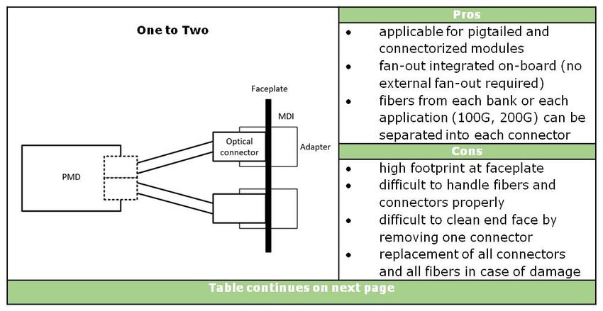
5.3.1 Fiber Management Inside a Coherent COBO-compliant OBO
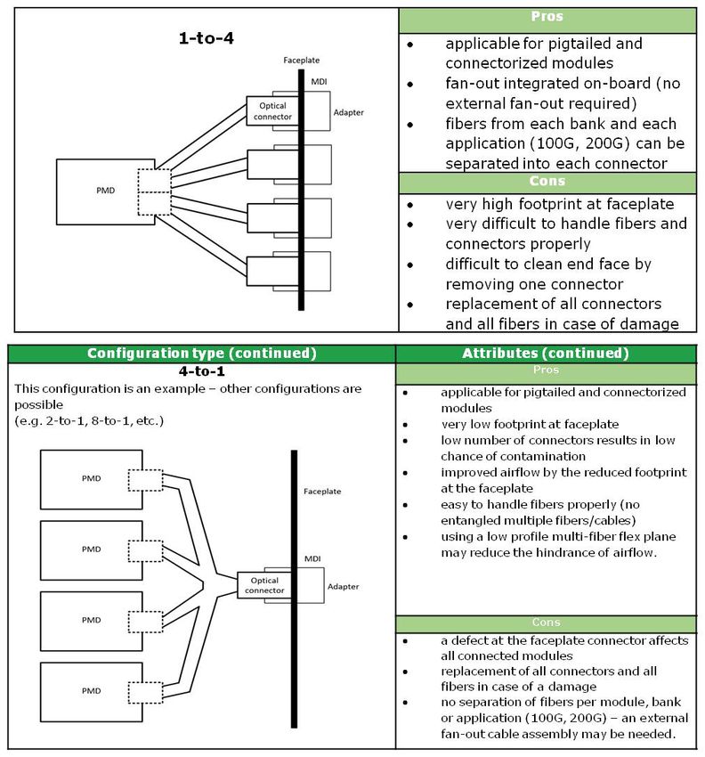
The multiple breakout options can be described as OBO configurations. In this section, the configurations
are named in terms of the number of OBOs to connectors, e.g. a 1-to-4 configuration has four connectors per
OBO, a 4-to-1 configuration has four OBOs sharing a single connector. Table 5-3 describes some configurations
and their pros and cons. Table 5-4 and Table 5-5 give the system implications in terms of applicable types and
required numbers of front-panel connectors. The difference between the tables is the size of OBO - with both
tables designed for switches with sixteen OBOs, utilizing a different system capacity, and assuming each OBO
lane is running at the same speed.
v1.1 ©March 2019 Page 28Connectivity Options for 400G+ OBO Application Note
TABLE 5-3 CONNECTIVITY OPTIONS
v1.1 ©March 2019 Page 29Connectivity Options for 400G+ OBO Application Note
Fibersª Connector at OBO Configuration Connectors per switch
Connector Type Faceplate per OBO type b with 16 OBOs
per OBO
1+1 Dual-LC, CS 1 1-to-1 16
Dual-LC, CS 2 1-to-2 32
2+2
MPO-12 c 1 1-to-1 16
4+4 MPO-12 1 1-to-1 16
MPO-12 (two row)
8+8 1 1-to-1 16
MPO-16 c
TABLE 5-4 CONNECTIVITY OPTIONS
Fibersª Fibersª per OBO Connector at OBO Configuration Connectors per switch
Connector Type type with 16 OBOs
per bank with 2 banks Faceplate per OBO
b
Separate Optical Ports of Bank 1 and 0
1+1 2+2 Dual-LC, CS 2 1-to-2 32
Dual-LC, CS 4 1-to-4 64
2+2 4+4
MPO-12 c 1 1-to-1 16
4+4 8+8 MPO-12 2 1-to-2 32
MPO-12 (two row)
8+8 16+16 2 1-to-2 32
MPO-16 c
Combined Optical Ports of Bank 1 and 0
1+1 2+2 Dual-LC, CS 2 1-to-2 32
2+2 4+4 MPO-12 1 1-to-1 16
4+4 MPO-12 (two row)
8+8 c 1
MPO-16 1-to-1 16
8+8 16+16 MPO-12 (two row) 1 1-to-1 16
TABLE 5-5 OBO CONFIGURATION TYPES FOR 16-LANE OBO AND TOTAL NUMBER OF CONNECTORS FOR A 16 OBO SWITCH
v1.1 ©March 2019 Page 30Connectivity Options for 400G+ OBO Application Note
6. CLEANING OF CONNECTOR FACES
6.1 Importance of Connector End Face Cleanliness
Cleanliness of the connector end face is critical to having a good link in an optical network. Optical signals in
single-mode fibers have a beam diameter of only roughly 9 μm. Any small particles of dust at any connectivity
point of an optical link may cause excess reflection, excess insertion loss or even fiber damage.
FIGURE 6-1: CLEAN VS DIRTY CONNECTION
6.2 Standards for Connector End Face Cleanliness
The IEC 61300-3-35 [24] standard outlines the pass/fail threshold level for the visual requirements for the end
face quality of polished fiber for multiple return loss grades. This specification covers inspections of the core,
the cladding, the adhesive and the contact and mandates the size and number of scratches and defects that are
acceptable. The specification covers PC-polished connectors (for both single-mode and multimode fiber) and
angle-polished connectors (single-mode fiber).
v1.1 ©March 2019 Page 31Connectivity Options for 400G+ OBO Application Note
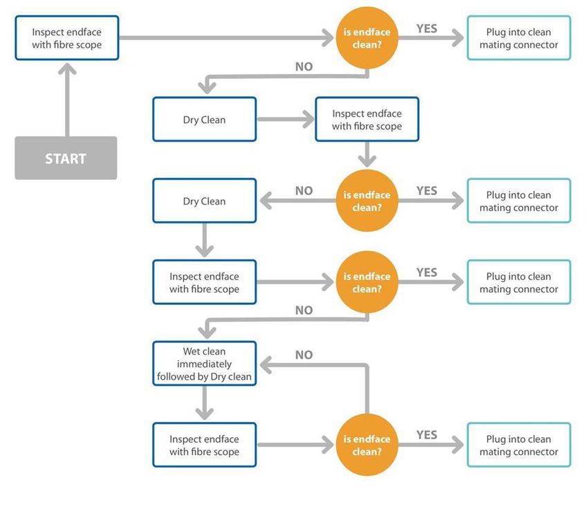
6.3 Cleaning Methods
Removing contaminants from optical fiber and bulk heads without damaging the fiber requires special optical
cleaning tools. Two categories of tools have been established: dry cleaning tools and wet cleaning tools. Below is
an overview of these tools and cleaning techniques, but complete details can be found in IEC TR 62627-01 [25]
6.3.1 Cleaning Types/Tools
Pen Cleaner
Pen cleaners have a reel of cleaning cloth that rotates at the tip of the cleaner when it is pressed against a con-
nector in a bulk head adapter or directly onto a connector if a fitting is placed onto the tip. This instrument with
a “push and click” mechanism cleans the ferrule end faces removing dust, oil and other debris without nicking
or scratching the end face. There are three main types of pen cleaners suitable for 2.5 mm, 1.25 mm and MPO
connectors.
Cartridge Cleaners
With this tool, a small window is opened to expose the cleaning cloth when the lever is pressed. This will also
turn the cleaning cloth so that a clean cloth section is used for every clean. The connector end face is pressed and
wiped against the cloth. For a more effective clean, specially treated cleaning cloth that prevents electrostatic
charge buildup can be used.
Lint Free Wipes
Lint-free wipes are not usually used to clean connector end face. The operation of wiping the connector end face
with a lint free wipe requires delicate skill to avoid damaging the connector end face.
Lint Free Swabs
Lint free swabs can be used to clean the internal barrel of a bulkhead adapter or the connector end face which
is terminated in a bulkhead adapter.
Adhesive-Backed Cleaner
Adhesive-backed cleaners have a sticky tip with a soft backing at the top of the cleaner. This cleaner is pressed
onto the end face of a bare connector or when terminated in a bulkhead adapter. The soft adhesive removed
dust and other particles.
v1.1 ©March 2019 Page 32You can also read