Design, Simulation, and Testing of a Custom Co- Processor for Cubesatellites in LEO - Justin Heimerl
←
→
Page content transcription
If your browser does not render page correctly, please read the page content below
Design, Simulation, and Testing of a Custom Co-
      Processor for Cubesatellites in LEO
                  Justin Heimerl
Introduction - Current State
●   Current rad-tolerant compute systems in LEO are several generations behind.
     ○   Hard to do things like real time image processing on a traditional rad hard system.
●   Various attempts being made to place more modern (but cheap) compute systems
    in space. (PyCubed - SAMD51, NASA PhoneSat - Snapdragon, probably Starlink)
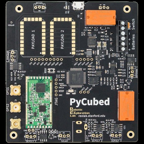
Introduction - CORGI
●   CORGI - Core GPU Interface
     ○   NVIDIA TX2i Carrier Board/Dev Board
     ○   Plug and play with PC/104+ stack
     ○   Flying on Multiview On Board
         Computational Imager (MOCI) mission
         in 2022.
●   NVIDIA TX2i
     ○   NVIDIA SoM (System on Module)
     ○   256 CUDA Cores (Parallel Processors)
     ○   64bit quad core ARM A57 Complex
         (Super Scaler, DSP, FPU, L1 ECC)
     ○   8GB 128 bit - LPDDR4 with ECC
Design - Peripherals
●   Final revision will contain various peripherals.
      Peripheral                               Purpose

      1x SD Card                               Modified filesystem/Mass storage

      2x USB A 3.0                             Payload Interface (Dual Imager)

      1x SPI                                   OBC Interface

      1x UART (115200 8N1)                     OBC Interface

      1x HDMI                                  Development Interface
Design - Layout
●   Need to be careful with high speed signals (rule of thumb >1GHz).
     ○   Impedance (capacitance/inductance) MUST be taken into account. Can use online calculators or field
         solver.
     ○   If concerned over impact of vias or other discontinuities, like stubs, consider rise times (See High
         Speed Digital Design - Johnson)
●   Large copper area for power planes.
     ○   More capacitance is better. TX2i requires little oscillation in main power rail.
     ○   Ground planes are all one continuous plane. Breaking this rule is quite bad, especially if routing a high
         speed signal over the plane. Energy travels in the dielectric.
Design - Component Selection
● Use temperature stable passives. (EX: X7R capacitors)
● High Speed Digital Components
○ We avoid common mode chokes. Can use if EMI is a problem.
○ Small as possible AC coupling capacitors, low ESR/ESL. (We use 0402, board house will charge extra to
place 0204).
○ RCLAMP524PA for ESD protection.
○ AC coupling capacitors should be close as possible to transmitter to minimize effect of reflections.Radiation - Total Ionizing Dose
● No TID testing published on TX2i (hopefully coming soon).
● Testing has been done on Jetson Nano (Slater).
○ Device can likely survive 20 krad.
● Testing also carried out on NVIDIA 600 series chipset (Steele).
○ Devices all survive past 6 krad.
Orbit Heliosynchronous
Apogee 500 km
Perigee 500 km
Inclination 97.4 degreesRadiation - Single Event Effects
● SEE data is available for TX2. (Wyras)
○ Devices have the same GPU, CPU, Memory
Architecture. TX2i has ECC.
○ Device tested with 200 MeV protons.
○ Functional Interrupts experienced quickly,
but mostly fixed by reset.
● How often are particles with these
energies encountered?
○ Not so often. (Only in South Atlantic
Anomaly)
○ Simulated flux ~7 orders of magnitude less
than experiment above.Radiation - Mitigation
● Currently use Dunmore Aerospace SatKit.
○ .1mm thick, 99% aluminum.
● TX2i contains SBE correct DBE detect capability in the
DRAM.
○ This is unique to TX2i.
● We use a triplicated filesystem.
○ Image hash computed at boot to find uncorrupted filesystem.
● Onboard computer (SmartFusion 2) also serves as
remote watchdog with reset capability.Simulation and Test - Power Circuitry
● TX2i requires power handling circuitry to function
correctly.
○ Board designer needs to implement dirty power detection circuit
and discharge circuit.
○ Circuit simulation in LTSpice. System tested with Clyde Space
EPS.Simulation and Test - Communications
● Current revision of the board only has UART available to communicate with OBC. SPI
to be added.
○ Tested file transfer speeds with 115200 baud 8N1.
○ System is ready to be used with arbitrary OBC, however UART is slow.Simulation and Test - GPU - Power
● Total system power draw measured.
○ When idle approximately 5000-6000mW.
○ When GPU is actively computing total draw maxes out around
9100mW.
● Two power tests carried out:
○ VGG-19 Jetson Benchmark (NVIDIA).
○ Linux “stress” tool with gpu_burn utility (Timonen).
● Tests also need to be carried in TVAC in the future.VGG-19 Parameters and Results
● GPU placed in max throughput mode, clock speed of 1.122 GHz, workspace size of
1024. 3 runs total were carried out.
GPU RESULTS CPU Resultsgpu_burn Parameters and Results
● Tool used in conjunction with Linux stress tool.
○ All CPU cores at 100% utilization for 3600 seconds.
○ Room temperature.
○ GPU temperature and board temperature reach 68.5 ℃ and 65 ℃ respectively. (TX2i operating
range from -40 ℃ to 85 ℃ )Simulation and Test - GPU - Bandwidth
● CUDA Bandwidth Test was utilized to determine Host to Device (CPU to GPU),
Device to Host (GPU to CPU), and Device to Device (GPU to GPU) bandwidth.
○ Test run for 2.1 minutes/run.
○ Tests run after power tests to measure stress, no off nominal results from unstressed TX2i.Conclusions
● Board can currently serve as development environment in a PC/104+ stack.
○ Allows access to far more compute resources for parallel tasks than are traditionally available without
utilizing an FPGA.
● External communications, power sequencing, command and control tested and
verified.
● Currently at TRL 4 - Appropriate for use as an engineering model.
● Need TID results and TVAC testing. System will fly on MOCI satellite in 2022.Thank You! Authors: Justin Heimerl, Alex Lin, Allen Spain, David Cotten, Ph.D. Email: jpheimerl@gmail.com, alexandria.lin@ngc.com, allen.spain@crosstrac.com, dcotte1@uga.edu Web: http://smallsat.uga.edu/ This work was funded by the Air Force Research Lab University Nanosatellite Program.
Citations
1. George Salazar and Glen Steele. Commercial Off the Shelf (COTS) Graphics Processing Board (GBP) Radiation Test
Evaluation Report. National Aeronautics and Space Administration, 2013

2. W. S. Slater, N. P. Tiwari, T. M. Lovelly, and J. K. Mee. Total Ionizing Dose Radiation Testing of NVIDIA Jetson Nano GPUs.
2020 IEEE High Performance Extreme Computing Conference (HPEC), 2020.

3. E.J Wyras. Proton Testing of an NVIDIA Jet- son TX2. National Aeronautics and Space Administration, 2019.

4. Ville Timonen. Multi-GPU Stress Test. 2012. URL: http://wili.cc/blog/gpu-burn.html.
You can also read