EMC TEST-REPORT TEST REPORT NUMBER: EFSH19010936-IE-01-E01 - Amazon AWS
←
→
Page content transcription
If your browser does not render page correctly, please read the page content below
EUROFINS PRODUCT TESTING SERVICE (SHANGHAI) CO., LTD

                      EMC TEST- REPORT

                    TEST REPORT NUMBER: EFSH19010936-IE-01-E01

Eurofins Product Testing Service (Shanghai) Co., Ltd                          Phone: +86-21-61819181
No. 395 West Jiangchang Road, Jing’an District,                               Fax: +86-21-61819299
Shanghai, 200436, P.R. China                                                  Page 1 of 34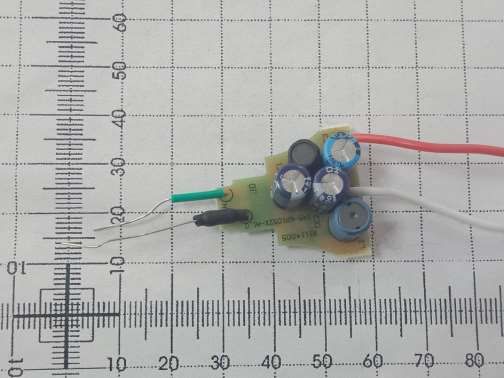
TABLE OF CONTENTS
1 Contents

1            Contents                                                                                   2

2            General Information                                                                        3
2.1   Notes                                                                                             3
2.2   Testing laboratory                                                                                4
2.3   Details of approval holder                                                                        5
2.4   Application details                                                                               5
2.5   EUT information                                                                                   5
2.6   Test standards                                                                                    5

3            Technical test                                                                             6
3.1   Summary of test results                                                                           6
3.2   Test environment                                                                                  6
3.3   Test mode                                                                                         6
3.4   List of Test equipment                                                                            7
3.5   Test results                                                                                      9

4            Emission Test                                                                              10
4.1   Conducted Emission                                                                                10
4.2   Radiated electromagnetic disturbances                                                             13
4.3   Radiated disturbance                                                                              17
4.4   Voltage Changes, Voltage Fluctuations and Flicker                                                 20

5            Immunity Test                                                                              21
5.1   Performance Criteria Description in Clause 4 of EN 61547                                          21
5.2   Conditions during testing                                                                         21
5.3   ESD                                                                                               22
5.4   Radio frequency electromagnetic fields                                                            23
5.5   Electrical Fast Transients                                                                        24
5.6   Injected currents(RF continues conducted)                                                         25
5.7   Surge Immunity                                                                                    26
5.8   Voltage dips and Interruption                                                                     27

6            Test setup Photos                                                                          28

7            EUT Photos                                                                                 32

                                 Test Report No.: EFSH19010936-IE-01-E01
                                 Eurofins Product Testing Service (Shanghai) Co., Ltd
                      No. 395 West Jiangchang Road, Jing’an District, Shanghai, 200436, P.R. China
                                                                                                     Page 2 of 34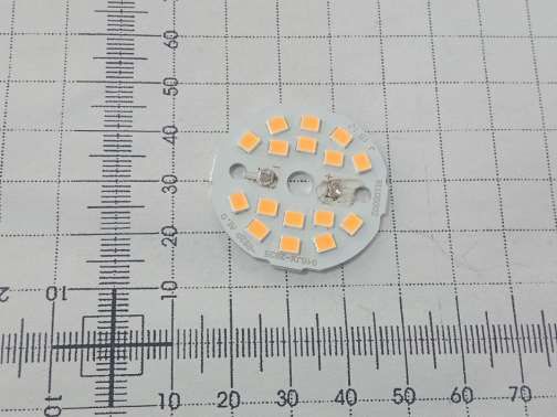
2      General Information

2.1 Notes
The results of this test report relate exclusively to the item tested as specified in chapter “Description of test
item” and are not transferable to any other test items.
Eurofins Product Testing Service (Shanghai) Co., Ltd. is not responsible for any generalisations and
conclusions drawn from this report. Any modification of the test item can lead to invalidity of test results and
this test report may therefore be not applicable to the modified test item.
The test report may only be reproduced or published in full. Reproducing or publishing extracts of the report
requires the prior written approval of the Eurofins Product Testing Service (Shanghai) Co., Ltd.
This document is subject to the General Terms and Conditions and the Testing and Certification System of
Eurofins Product Testing Service (Shanghai) Co., Ltd. available on request or accessible at
www.pt.eurofins.com.

Operator:

2019-01-24                                Perry Li / Project Engineer

Date             Eurofins-Lab.             Name / Title                         Signature

Technical responsibility for area of testing:

2019-01-24                                Andy Li / Supervisor

Date             Eurofins                  Name / Title                         Signature

                                   Test Report No.: EFSH19010936-IE-01-E01
                                   Eurofins Product Testing Service (Shanghai) Co., Ltd
                        No. 395 West Jiangchang Road, Jing’an District, Shanghai, 200436, P.R. China
                                                                                                       Page 3 of 34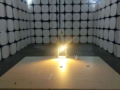
2.2       Testing laboratory

Eurofins Product Testing Service (Shanghai) Co., Ltd
No. 395 West Jiangchang Road, Jing’an District, Shanghai, 200436, P.R. China
Telephone : +86-21-61819181
Fax         : +86-21-61819299

Test location, where different:

Name                      : Shenzhen SEM.Test Technology Co., Ltd.
Address                   : 1/F., Room 101, Building 1, Hongwei Industrial Park, Liuxian'er Road, Block 70,
                             Bao'an District, Shenzhen, Guangdong, China
Telephone                  : +86-755-3366 3308
Fax                        : +86-755-3366 3309

All items were prepared and tested at Shenzhen SEM.Test Technology Co., Ltd.

                                  Test Report No.: EFSH19010936-IE-01-E01
                                  Eurofins Product Testing Service (Shanghai) Co., Ltd
                       No. 395 West Jiangchang Road, Jing’an District, Shanghai, 200436, P.R. China
                                                                                                      Page 4 of 34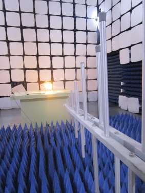
2.3       Details of approval holder
Name                                      :   Foshan Electrical and Lighting Co., Ltd.
Address                                   :   64 North Fenjiang Road, Foshan, Guangdong, China
Telephone                                 :   ./.
Fax                                       :   ./.

2.4       Application details
Date of receipt of test item              : 2019-01-11
Date of test                              : 2019-01-14 to 2019-01-17

2.5       EUT information
Product type                           : LED Lamps
Model name                             : G45-7-**/A11F/11, G45-7-**/A12F/11, G45-7-**/A13F/11,
                                         G45-7-**/A14F/11
                                         (The “**” means colour temperature, it can be integer number from
                                          18 to 65, indicating the colour temperature is 1800K to 6500K)
Brand name                             : FSL
Serial number                          : ./.
Ratings                                : 220-240V~, 50Hz, 7W
Test voltage                           : AC 230V, 50Hz
Additional information                 :
1. The product is self-ballasted LED lamp
   Model                   Rating                                                       Lamp Cap
 G45-7-**/A11F/11          220-240V~, 50/60 Hz, 7W, 55mA, non-dimmable                                E14
 G45-7-**/A12F/11          220-240V~, 50/60 Hz, 7W, 55mA, non-dimmable                                E27
 G45-7-**/A13F/11          220-240V~, 50/60 Hz, 7W, 55mA, non-dimmable                                B22
 G45-7-**/A14F/11          220-240V~, 50/60 Hz, 7W, 55mA, non-dimmable                                B15d

2. All models are identical except appearance and lamp holder.
3. Model G45-7-27/A12F/11 is selected to test full items.

2.6 Test standards
Technical standard :

EN 55015:2013+A1:2015
EN 61547:2009
EN 61000-3-2:2014
EN 61000-3-3:2013

                                  Test Report No.: EFSH19010936-IE-01-E01
                                  Eurofins Product Testing Service (Shanghai) Co., Ltd
                       No. 395 West Jiangchang Road, Jing’an District, Shanghai, 200436, P.R. China
                                                                                                             Page 5 of 34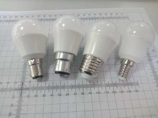
3     Technical test

3.1        Summary of test results

No deviations from the technical specification(s) were ascertained in the course
of the tests performed.

or

The deviations as specified were ascertained in the course of the tests
performed.

3.2        Test environment

Temperature                               : 20     ...   24°C

Relative humidity content                 : 30     ...   55%

Air pressure                              : 100    ...   103kPa

3.3        Test mode

Lighting

                                  Test Report No.: EFSH19010936-IE-01-E01
                                  Eurofins Product Testing Service (Shanghai) Co., Ltd
                       No. 395 West Jiangchang Road, Jing’an District, Shanghai, 200436, P.R. China
                                                                                                      Page 6 of 34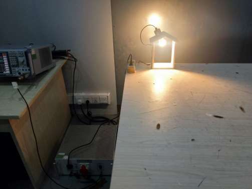
3.4 List of Test equipment
     Equipment Name                  Manufactory                 Model             Serial No.        Cal Due date

     Spectrum Analyzer             Rohde & Schwarz                FSP             836079/035         2019-06-11

     EMI Test Receiver             Rohde & Schwarz               ESVB             825471/005         2019-06-11

          Amplifier                      Agilent                 8447F           3113A06717          2019-06-11

  Trilog Broadband Antenna           Schwarz beck              VULB9163            9163-333          2019-06-07

       Loop Antenna                    EVERFINE                  LLA-2              711001           2019-06-07

           Clamp                          Luthi                  MDS21                3809           2019-06-22

     EMI Test Receiver             Rohde & Schwarz                ESCI              101611           2019-06-11

        Pulse Limiter              Rohde & Schwarz             ESH3-Z2              100911           2019-06-11

          AC LISN                    Schwarz beck              NSLK8126            8126-224          2019-06-11

   Digital Power Analyzer        California Instrument            CTS                72831           2019-06-11

                                                             5001IX-CTS-
       Power Source              California Instrument                               25965           2019-06-11
                                                                 400

       Horn Antenna                        ETS                    3117             00086197          2018-06-07

                                                                PAP-0118             24002
        Pre-amplifier            Compliance Direction                                                 2019-06-11

                                                                                                     2019-08-14
      ESD Generator                     LIONCEL                ESD-203B             0170901

       Transient 2000               EMC PARTNER                TRA2000                 863           2019-06-11

       Couple Clamp                 EMC PARTNER              CN-EFT1000             CH-4242          2019-06-11

            CDN                           Luthi                CDNL-801               2655           2019-06-11

                                                                 MA-
         Attenuator                       EMCI                                        1009           2019-06-11
                                                              5100/6BF2

    CS Immunity Tester               SCHAFFNER                 NSG2070                1123           2019-06-11

      Signal Generater                     R&S                 SMB100A              105942           2019-09-10

                                                             BLWA0830-
     RF Power Amplifier            BONN Elektronik                                  128740           2019-09-10
                                                             160/100/40D
                                                               NTWPAS-
     RF Power Amplifier                   NJNT                                      2560025          2019-09-10
                                                                2560025
  Gestockte Breitband(S ta
                                   SCHWARZBECK                STLP9128D                043           2019-09-10
  cked) Log.-per.Antenna

                                 Test Report No.: EFSH19010936-IE-01-E01
                                 Eurofins Product Testing Service (Shanghai) Co., Ltd
                      No. 395 West Jiangchang Road, Jing’an District, Shanghai, 200436, P.R. China
                                                                                                          Page 7 of 34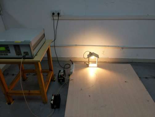
BBHA 9120
Broad-band Horn Antenna       SCHWARZBECK                                         667           2019-09-10
                                                             D

     Power Meter                      R&S                   NRP2               102031           2019-09-10

                            Test Report No.: EFSH19010936-IE-01-E01
                            Eurofins Product Testing Service (Shanghai) Co., Ltd
                 No. 395 West Jiangchang Road, Jing’an District, Shanghai, 200436, P.R. China
                                                                                                    Page 8 of 34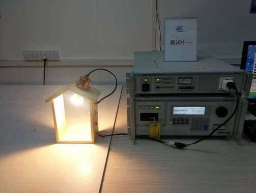
3.5        Test results
               1st test                    test after modification                                production test

                     Test case                           Sub clause          Required       Test passed    Test failed

                                                       Clause 4.3 of
      Conducted Emission
                                                         EN 55015

      Radiated electromagnetic                         Clause 4.4 of
      disturbances                                       EN 55015
                                                      Clause 4.4.2 of
      Radiated disturbance
                                                         EN 55015

      Harmonic Current Emissions                       EN 61000-3-2

      Voltage Changes, Voltage Fluctuations
                                                       EN 61000-3-3
      and Flicker

      Electrostatic Discharge                           Clause 5.2 of
                                                        EN 61547 &
                                                       IEC 61000-4-2

      Radio frequency electromagnetic fields            Clause 5.3 of
                                                        EN 61547 &
                                                       IEC 61000-4-3

      Power frequency magnetic fields                   Clause 5.4 of
                                                        EN 61547 &
                                                       IEC 61000-4-8

      Electrical Fast Transients                        Clause 5.5 of
                                                        EN 61547 &
                                                       IEC 61000-4-4

      Injected currents                                 Clause 5.6 of
                                                        EN 61547 &
      (RF common mode)                                 IEC 61000-4-6

      Surge immunity                                    Clause 5.7 of
                                                        EN 61547 &
                                                       IEC 61000-4-5

      Voltage dips and short interruption              Clause 5.8 of
                                                        EN 61547 &
                                                      IEC 61000-4-11

  Note:
  1. Power frequency magnetic fields test was not required as the EUT did not contained components
     susceptible to magnetic fields.
  2. The EUT is LED light power< 25W, which doesn't belong to discharge lighting equipment, thus
     harmonic current emission test is not applicable according to EN 61000-3-2 requirement.

                                     Test Report No.: EFSH19010936-IE-01-E01
                                     Eurofins Product Testing Service (Shanghai) Co., Ltd
                          No. 395 West Jiangchang Road, Jing’an District, Shanghai, 200436, P.R. China
                                                                                                               Page 9 of 34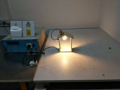
4       Emission Test
4.1 Conducted Emission
This clause lays down the general requirements for the measurement of disturbance voltage produced at the
terminals of apparatus.

4.1.1     Limits

                                                                     At mains terminals
     Frequency range
                                                                         dB (μV)
            MHz
                                                 Quasi-peak                                        Average
        0.009 to 0.05                                 110                                              --
         0.05 to 0.15                              90 to 80                                            --
         0.15 to 0.50                              66 to 56                                        56 to 46
          0.50 to 5                                   56                                               46
           5 to 30                                    60                                               50
Note1: The limit decreases linearly with the logarithm of the frequency in the range 50k to 150kHz and 150
kHz to 0.5 MHz.
Note2: The lower limit is applicable at the transition frequency.

4.1.2     Measurement procedure

1. The mains terminal disturbance voltage was measured with the EUT in a shielded room.
2. The EUT was connected to AC power source through a LISN (Line Impedance Stabilization Network)
   which provides a (50 μH + 5 Ω) || 50 Ω linear impedance. The power cables of all other units of the
   EUT were connected to a second LISN, which was bonded to the ground reference plane in the same
   way as the LISN for the unit being measured.

                                   Test Report No.: EFSH19010936-IE-01-E01
                                   Eurofins Product Testing Service (Shanghai) Co., Ltd
                        No. 395 West Jiangchang Road, Jing’an District, Shanghai, 200436, P.R. China
                                                                                                              Page 10 of 34
3. The table top EUT was placed upon a non-metallic table 0.8m above the ground reference plane. And for
floor-standing arrangement, the EUT was placed on the horizontal ground reference plane, but separated
from metallic contact with the ground reference plane by 0.1m of insulation.
4. Before get the final emission results with quasi-peak(QP) detector and average(AV) detector, a pre-scan
was performed with the peak(PK) and average(AV) detector to find out the maximum emission data plots
of the EUT.
4.1.3 Measurement uncertainty
Ulab(cond) = 1.8dB at 95% level of confidence, k=2
4.1.4 Results -Measurement Data
Job No.: ce Phase: L1
Standard: EN55015 Conduction(QP) Power Source: AC 230V/50Hz
Test item: Conduction Test Date: 19/01/15/
Temp.(℃)/Hum.(%RH): 23.5℃/55%RH Time: 8/50/25
Note:
No. Frequency Reading Correct Result Limit Over Detector
(MHz) (dBuV) (dB) (dBuV) (dBuV) (dB)
1* 0.1860 48.53 10.12 58.65 64.21 -5.56 QP
2 0.1860 35.34 10.12 45.46 54.21 -8.75 AVG
3 0.3700 39.39 9.98 49.37 58.50 -9.13 QP
4 0.3700 25.52 9.98 35.50 48.50 -13.00 AVG
5 1.8780 16.08 10.01 26.09 46.00 -19.91 AVG
6 2.1300 32.97 10.01 42.98 56.00 -13.02 QP
Test Report No.: EFSH19010936-IE-01-E01
Eurofins Product Testing Service (Shanghai) Co., Ltd
No. 395 West Jiangchang Road, Jing’an District, Shanghai, 200436, P.R. China
Page 11 of 34Job No.: ce Phase: N
Standard: EN55015 Conduction(QP) Power Source: AC 230V/50Hz
Test item: Conduction Test Date: 19/01/15/
Temp.(℃)/Hum.(%RH): 23.5℃/55%RH Time: 8/55/15
Note:
No. Frequency Reading Correct Result Limit Over Detector
(MHz) (dBuV) (dB) (dBuV) (dBuV) (dB)
1* 0.1860 46.87 10.12 56.99 64.21 -7.22 QP
2 0.1860 33.60 10.12 43.72 54.21 -10.49 AVG
3 0.3700 38.98 9.98 48.96 58.50 -9.54 QP
4 0.3700 25.11 9.98 35.09 48.50 -13.41 AVG
5 2.1220 14.61 10.01 24.62 46.00 -21.38 AVG
6 2.3660 32.22 10.01 42.23 56.00 -13.77 QP
Test Report No.: EFSH19010936-IE-01-E01
Eurofins Product Testing Service (Shanghai) Co., Ltd
No. 395 West Jiangchang Road, Jing’an District, Shanghai, 200436, P.R. China
Page 12 of 344.2 Radiated electromagnetic disturbances
This clause lays down the general requirements for the magnetic component of the radiated disturbance field
strength in the frequency range 9 kHz to 30 MHz
4.2.1 limits
Limits for loop diameter
Frequency range
dB (μA)
Hz
2m
9 kHz to 70 kHz 88
70 kHz to 150 kHz 88 to 58
150 kHz to 3 MHz 58 to 22
3 MHz to 30 MHz 22
Note: At the transition frequency, the lower limit applies.
Decreasing linearly with the logarithm of the frequency.
Increasing linearly with the logarithm of the frequency.
4.2.2 Measurement procedure
Test Report No.: EFSH19010936-IE-01-E01
Eurofins Product Testing Service (Shanghai) Co., Ltd
No. 395 West Jiangchang Road, Jing’an District, Shanghai, 200436, P.R. China
Page 13 of 34The EUT is placed in the centre of the loop antenna system. The current induced by the magnetic field from
the EUT into each of the three large loop antennas of the loop antenna system is measured by connecting
the current probe of the large loop antenna to a measuring receiver. During the measurements the EUT
remains in a fixed position. Before get the final emission results with quasi-peak (QP) detector, a pre-scan
was performed with the peak (PK) to find out the maximum emission data plots of the EUT.
4.2.3 Results
Job No.: ce Phase: X
Standard: EN 55015 Three Loop Power Source: AC 230V/50Hz
Test item: Conduction Test Date: 19/01/15/
Temp.(℃)/Hum.(%RH): 23.5℃/55%RH Time: 9/06/57
Note:
No. Frequency Reading Correct Result Limit Over Detector
(MHz) (dBuA) (dB) (dBuA) (dBuA) (dB)
1 0.0100 1.83 38.96 40.79 88.00 -47.21 QP
2 0.0620 -2.35 22.97 20.62 88.00 -67.38 QP
3 0.7780 -13.42 20.07 6.65 38.22 -31.57 QP
4* 1.4900 -15.84 20.30 4.46 30.41 -25.95 QP
5 6.0300 -24.89 20.75 -4.14 22.00 -26.14 QP
6 16.6900 -25.28 20.93 -4.35 22.00 -26.35 QP
Test Report No.: EFSH19010936-IE-01-E01
Eurofins Product Testing Service (Shanghai) Co., Ltd
No. 395 West Jiangchang Road, Jing’an District, Shanghai, 200436, P.R. China
Page 14 of 34Job No.: ce Phase: Y
Standard: EN 55015 Three Loop Power Source: AC 230V/50Hz
Test item: Conduction Test Date: 19/01/15/
Temp.(℃)/Hum.(%RH): 23.5℃/55%RH Time: 9/12/15
Note:
No. Frequency Reading Correct Result Limit Over Detector
(MHz) (dBuA) (dB) (dBuA) (dBuA) (dB)
1 0.0102 1.25 38.83 40.08 88.00 -47.92 QP
2 0.0696 -6.61 22.63 16.02 88.00 -71.98 QP
3 0.4820 -12.64 20.28 7.64 43.97 -36.33 QP
4* 1.4300 -14.11 20.27 6.16 30.90 -24.74 QP
5 4.4940 -23.64 20.68 -2.96 22.00 -24.96 QP
6 9.1940 -24.79 20.30 -4.49 22.00 -26.49 QP
Test Report No.: EFSH19010936-IE-01-E01
Eurofins Product Testing Service (Shanghai) Co., Ltd
No. 395 West Jiangchang Road, Jing’an District, Shanghai, 200436, P.R. China
Page 15 of 34Job No.: ce Phase: Z
Standard: EN 55015 Three Loop Power Source: AC 230V/50Hz
Test item: Conduction Test Date: 19/01/15/
Temp.(℃)/Hum.(%RH): 23.5℃/55%RH Time: 9/17/04
Note:
No. Frequency Reading Correct Result Limit Over Detector
(MHz) (dBuA) (dB) (dBuA) (dBuA) (dB)
1 0.0359 -7.14 26.76 19.62 88.00 -68.38 QP
2 0.1860 -9.13 20.79 11.66 55.41 -43.75 QP
3 1.4260 -15.38 20.27 4.89 30.94 -26.05 QP
4* 2.1260 -19.23 20.57 1.34 26.14 -24.80 QP
5 5.3580 -24.66 20.73 -3.93 22.00 -25.93 QP
6 11.7460 -24.89 20.43 -4.46 22.00 -26.46 QP
Test Report No.: EFSH19010936-IE-01-E01
Eurofins Product Testing Service (Shanghai) Co., Ltd
No. 395 West Jiangchang Road, Jing’an District, Shanghai, 200436, P.R. China
Page 16 of 344.3 Radiated disturbance
This clause lays down the general requirements for the measurement of Radiated disturbance
produced at the space of apparatus.
4.3.1 Limits
Frequency range Quasi-peak limits at 10m Quasi-peak limits at 3m
MHz dB (μV/m) dB (μV/m)
30 to 230 30 40
230 to 300 37 47
At transitional frequencies the lower limit applies.
4.3.2 Measurement procedure
1. The radiated emissions test was conducted in a semi-anechoic chamber. The EUT was placed upon a
non-metallic table 0.8m above the ground reference plane. And for floor-standing arrangement, the EUT was
placed on the horizontal ground reference plane, but separated from metallic contact with the ground
reference plane by 0.1m of insulation.
2. Before get the final emission results with quasi-peak(QP) detector, a pre-scan was performed with the
peak(PK) detector to find out the maximum emission data plots of the EUT.
3. The frequencies of maximum emission were determined in the final radiated emissions measurement, the
physical arrangement of the test system and associated cabling was varied in order to determine the effect
on the EUT's emissions in amplitude, direction and frequency. At each frequency, the EUT was rotated 360°,
and the antenna was raised and lowered from 1 to 4 meters in order to determine the maximum disturbance.
Measurements were performed for both horizontal and vertical antenna polarization. Test was performed on
subcontractor at 3 m distance.
Test Report No.: EFSH19010936-IE-01-E01
Eurofins Product Testing Service (Shanghai) Co., Ltd
No. 395 West Jiangchang Road, Jing’an District, Shanghai, 200436, P.R. China
Page 17 of 344.3.3 Measurement uncertainty
Ulab(cond) = 3.9dB at 95% level of confidence, k=2
4.3.4 Results
Job No.: RE Polarization: Horizontal
Standard: EN55015 Power Source: AC 230V/50Hz
Test item: Radiation Test Date: 19/01/14/
Temp.( 25( C)/55%RH Time: 13/48/06
C)/Hum.(%RH):
Note:
No. Frequency Reading Correct Result Limit Over Remark
(MHz) (dBuV) dB/m (dBuV/m) (dBuV/m) (dB)
1 51.1825 28.02 -11.59 16.43 40.00 -23.57 QP
2 63.1134 27.54 -13.75 13.79 40.00 -26.21 QP
3 106.1992 28.07 -13.50 14.57 40.00 -25.43 QP
4 120.2600 27.22 -15.58 11.64 40.00 -28.36 QP
5 219.8474 35.12 -12.16 22.96 40.00 -17.04 QP
6 267.3753 30.45 -9.01 21.44 47.00 -25.56 QP
Test Report No.: EFSH19010936-IE-01-E01
Eurofins Product Testing Service (Shanghai) Co., Ltd
No. 395 West Jiangchang Road, Jing’an District, Shanghai, 200436, P.R. China
Page 18 of 34Job No.: RE Polarization: Vertical
Standard: EN55015 Power Source: AC 230V/50Hz
Test item: Radiation Test Date: 19/01/14/
Temp.( 25( C)/55%RH Time: 13/46/56
C)/Hum.(%RH):
Note:
No. Frequency Reading Correct Result Limit Over Remark
(MHz) (dBuV) dB/m (dBuV/m) (dBuV/m) (dB)
1 51.3005 28.04 -11.59 16.45 40.00 -23.55 QP
2 61.8189 27.95 -13.57 14.38 40.00 -25.62 QP
3 90.3902 28.76 -13.48 15.28 40.00 -24.72 QP
4 140.3204 36.76 -17.26 19.50 40.00 -20.50 QP
5 219.8474 35.85 -12.16 23.69 40.00 -16.31 QP
6 269.2286 29.41 -9.07 20.34 47.00 -26.66 QP
Test Report No.: EFSH19010936-IE-01-E01
Eurofins Product Testing Service (Shanghai) Co., Ltd
No. 395 West Jiangchang Road, Jing’an District, Shanghai, 200436, P.R. China
Page 19 of 344.4 Voltage Changes, Voltage Fluctuations and Flicker
This part is concerned with the limitation of voltage fluctuations and flicker impressed on the public low-
voltage system.
4.4.1 Limits
Value Limit
Pst 1,0
Plt 0,65
dt 3,3%
dc 3,3%
dmax 4,0%
4.4.2 Measurementest procedure
The equipment under test is placed on a wooden table with a height of 0,8 m in the EMC lab. The voltage
changes, fluctuations and flicker were measured at the supply terminals of the EUT.
4.4.3 Results
Parameter values recorded during the test:
Vrms at the end of test (Volt): 231.50
T-max (mS): 0 Test limit (mS): 500.0 Pass
Highest dc (%): 0.00 Test limit (%): 3.30 Pass
Highest dmax (%): 0.00 Test limit (%): 4.00 Pass
Highest Pst (10 min. period): 0.064 Test limit: 1.000 Pass
Test Report No.: EFSH19010936-IE-01-E01
Eurofins Product Testing Service (Shanghai) Co., Ltd
No. 395 West Jiangchang Road, Jing’an District, Shanghai, 200436, P.R. China
Page 20 of 345 Immunity Test
5.1 Performance Criteria Description in Clause 4 of EN 61547
During the test, no change of the Iuminous intensity shall be observed and the regulating
Criterion A:
control, if any, shall operate during the test as intended.
During the test, the Iuminous intensity may change to any value. After the test, the
Iuminous intensity shall be restored to its initial value within 1 min. Regulating controls
Criterion B: need not function during the test, but after the test, the mode of the control shall be the
same as before the test provided that during the test no mode changing commands
were given.
During and after the test, any change of the luminous intensity is allowed and the
lamp(s) may be extinguished. After the test, within 30 min, all functions shall return to
normal, if necessary by temporary interruption of the mains supply and/or operating the
Criterion C:
regulating control. Additional requirement for lighting equipment incorporating a starting
device: After the test, the lighting equipment is switched off. After half an hour, it is
switched on again. The lighting equipment shall start and operate as intended.
5.2 Conditions during testing
The test shall be applied while the equipment is operated as intended under the normal operating conditions
as laid down in the relevant product standard at stabilized Iuminous (radiant) flux and at normal laboratory
conditions. Testing is only required at one combination of supply voltage and frequency, as specified by the
manufacturer. Equipment including a regulating control shall be tested at a light output level of 50 % ±
10 %.The lamp load of the equipment under test shall be the maximum allowed. Luminaires and independent
auxiliaries shall be tested with lamps for which they are intended. Where equipment can operate with lamps
of different wattages, lamps of maximum wattage shall be applied. For independent auxiliaries, the length of
the cables between device and lamp shall be 3 m unless the manufacturer prescribes another length.
Test Report No.: EFSH19010936-IE-01-E01
Eurofins Product Testing Service (Shanghai) Co., Ltd
No. 395 West Jiangchang Road, Jing’an District, Shanghai, 200436, P.R. China
Page 21 of 345.3 ESD
5.3.1 Test Procedures
1. Contact discharge was applied only to conductive surfaces of the EUT. Air discharge was applied only to
non-conducted surfaces of the EUT.
2. The EUT was put on a 0.8m high wooden table for table-top equipment or 0.1m high for floor standing
equipment standing on the ground reference plane (GRP).
3. A horizontal coupling plane(HCP) 1.6m by 0.8m in size was placed on the table, and the EUT with its
cables were isolated from the HCP by an insulating support thick than 0.5mm. The VCP 0.5m by 0.5m in
size while HCP were constructed from the same material type and thickness as that of the GRP, and
connected to the GRP via a 470kΩ resistor at each end. The distance between EUT and any of the other
metallic surfaces excepted the GRP, HCP and VCP was greater than 1m.
4. During the contact discharges, the tip of the discharge electrode was touching the EUT before the
discharge switch is operated. During the air discharges, the round discharge tip of the discharge
electrode was approached as fast as possible to touch the EUT. After each discharge, the ESD
generator was removed from the EUT, the generator is then retriggered for a new single discharge. For
ungrounded product, a discharge cable with two resistances was used after each discharge to remove
remnant electrostatic voltage. 10 times of each polarity single discharge were applied to HCP and VCP.
5.3.2 Results
Table (T) Contact (C) Voltage Number of Polarity
Test point Opinion
Floor (F) Air (A) (kV) discharge (+ / -)
Air discharge T A ±2, ±4, ±8 Mini 20/point +/- A
Contact discharge T C ±2, ±4 Mini 20/point +/- A
HCP T C ±2, ±4 Mini 20/point +/- A
VCP T C ±2, ±4 Mini 20/point +/- A
A: no loss of function.
Test Report No.: EFSH19010936-IE-01-E01
Eurofins Product Testing Service (Shanghai) Co., Ltd
No. 395 West Jiangchang Road, Jing’an District, Shanghai, 200436, P.R. China
Page 22 of 345.4 Radio frequency electromagnetic fields
5.4.1 Measurement procedure
1. The EUT was placed on 0.8m high wooden table for table-top equipment. For floor standing equipment,
the EUT was placed on a 0.1m high wooden support above the GRP. The tests normally shall be
performed with the generating antenna facing each of four sides of the EUT. When equipment can be used
in different orientations (e.g. vertical or horizontal) the test shall be performed on all possible sides of the
EUT.
2. The tests are carried out with a field strength by 3 V/m (measured in the unmodulated field) with amplitude
modulated signal by a depth of 80 % by a sinusoidal audio signal of 1 kHz. The logarithmic step was 1%
and the dwell time was 3s dependent of the EUT cycle time. Test was performed on subcontractor.
5.4.2 Results
Antenna
Frequency Range Field Strength Modulation Opinion
Polarity
80MHz-1GHz 3V/m 80% AM 1kHz Horizontal A
80MHz-1GHz 3V/m 80% AM 1kHz Vertical A
A: no loss of function.
Test Report No.: EFSH19010936-IE-01-E01
Eurofins Product Testing Service (Shanghai) Co., Ltd
No. 395 West Jiangchang Road, Jing’an District, Shanghai, 200436, P.R. China
Page 23 of 345.5 Electrical Fast Transients
5.5.1 Measurement procedure
1. The EUT was placed on a ground reference plane(GRP) insulated by an insulating support 0,1 m thick
and the GRP was placed on a 0.8m high wooden table for table-top equipment. For floor standing
equipment, the EUT was placed on a 0.1m high wooden support above the GRP.
2. The GRP shall project beyond the EUT and the clamp by at least 0.1m on all sides. The distance
between the EUT and any other of the metallic surface except the GRP was greater than 0.5m. All cables
to the EUT were placed on the insulation support 0.1m above GRP. Cables not subject to EFT were
routed as far as possible from cable under test to minimize the coupling between the cables.
3. The length of signal and power cable between the EUT and EFT generator was 0.5m. If the cable is a
non-detachable supply cable more than 0.5m, the excess length of this cable shall be folded to avoid a
flat coil and situated at a distance of 0.1m above the GRP.
5.5.2 Results
Repetition
Voltage Polarity Duration Waveform
Test port Frequency Opinion
(kV) (+ / -) (s or min) Tr / Th
(kHz)
a.c. port, L 1 +/- 2 min 5/50 ns 5 A
a.c. port, N 1 +/- 2 min 5/50 ns 5 A
a.c. port, L+N 1 +/- 2 min 5/50 ns 5 A
A: no loss of function.
Test Report No.: EFSH19010936-IE-01-E01
Eurofins Product Testing Service (Shanghai) Co., Ltd
No. 395 West Jiangchang Road, Jing’an District, Shanghai, 200436, P.R. China
Page 24 of 345.6 Injected currents(RF continues conducted)
5.6.1 Measurement procedure
1. The EUT was placed on an insulating support of 0.1m height above a ground reference Plane, arranged
and connected to satisfy its functional requirement. All cables exiting the EUT was supported at a height
of at least 30 mm above the ground reference plane.
2. The coupling and decoupling devices were required, they were located between 0,1 m and 0,3 m from
the EUT. This distance was to be measured horizontally from the projection of the EUT on to the ground
reference plane to the coupling and decoupling device.
3. The frequency range was swept from 150 kHz to 80 MHz, using the signal levels established during the
setting process, and with the disturbance signal 80 % amplitude modulated with a 1 kHz sine wave,
pausing to adjust the RF signal level or to change coupling devices as necessary. Where the frequency
was swept incrementally, the step size does not exceed 1 % of the preceding frequency value. The dwell
time of the amplitude modulated carrier at each frequency was not less than the time necessary for the
EUT to be exercised and to respond, and was not less than 3 s.
5.6.2 Results
Voltage
Test port Modulation Frequency Range Opinion
(e.m.f.)
AC power line 3V 80% AM 1 kHz 150 kHz - 80 MHz A
A: no loss of function.
Test Report No.: EFSH19010936-IE-01-E01
Eurofins Product Testing Service (Shanghai) Co., Ltd
No. 395 West Jiangchang Road, Jing’an District, Shanghai, 200436, P.R. China
Page 25 of 345.7 Surge Immunity
5.7.1 Measurement procedure
1. The EUT was placed on a ground reference plane(GRP) insulated by an insulating support 0,1 m thick
and the GRP was placed on a 0.8m high wooden table for table-top equipment. For floor standing
equipment, the EUT was placed on a 0.1m high wooden support above the GRP.
2. The 1,2/50 μs surge was to be applied to the EUT power supply terminals via the capacitive coupling
network .Decoupling networks were required in order to avoid possible adverse effects on equipment not
under test that may be powered by the same lines and to provide sufficient decoupling impedance to the
surge wave so that the specified wave may be applied on the lines under test.
3. Pulses shall be applied to the a.c. voltage wave as follows; five positive polarity pulses at the 90ºphase
angle, five negative polarity pulses at the 270ºphase angle.
5.7.2 Results
Polarity Voltage Voltage Current Repetition Number of
Test port Opinion
(+ / -) ( kV ) Waveform Waveform Rate pulses
a.c. port, L-N +/- 0.5 1.2/50 µs 8/20 µs 1 per min 5 /point B
A: no loss of function.
B: the appliance would not work normally during the test, but after test it would recover.
Test Report No.: EFSH19010936-IE-01-E01
Eurofins Product Testing Service (Shanghai) Co., Ltd
No. 395 West Jiangchang Road, Jing’an District, Shanghai, 200436, P.R. China
Page 26 of 345.8 Voltage dips and Interruption
5.8.1 Measurement procedure
Phase
switch 1
Power Voltage meter
supply Oscilloscope
switch 2 EUT
Neutral
1. The EUT was placed on a ground reference plane(GRP) insulated by an insulating support 0,1 m thick
and the GRP was placed on a 0.8m high wooden table for table-top equipment. For floor standing
equipment, the EUT was placed on a 0.1m high wooden support above the GRP.
2. The test was performed with the EUT connected to the test generator with the shortest power supply
cable as specified by the EUT manufacturer.Changes to the voltage level shall occur at a zero crossing
point in the a.c. voltage waveform.
3. The EUT was tested for each selected combination of test level and duration with a sequence of three
dips /interruptions with intervals of 10 s minimum. Each representative mode of operation was tested.
5.8.2 Results
Reduction of supply Duration in parts of
Test level in % UT Opinion
voltage period (in ms)
100% 0 0,5 (10 ms) B
30 % 70 10 (200 ms) B
A: no loss of function.
B: the appliance would not work normally during the test, but after test it would recover.
Test Report No.: EFSH19010936-IE-01-E01
Eurofins Product Testing Service (Shanghai) Co., Ltd
No. 395 West Jiangchang Road, Jing’an District, Shanghai, 200436, P.R. China
Page 27 of 346 Test setup Photos
Radiated Disturbance Test Setup
Conducted Emission Test Setup
Test Report No.: EFSH19010936-IE-01-E01
Eurofins Product Testing Service (Shanghai) Co., Ltd
No. 395 West Jiangchang Road, Jing’an District, Shanghai, 200436, P.R. China
Page 28 of 34Radiated Electromagnetic Disturbances Test Setup
Current Harmonics /Voltage Flicker Test Setup
Test Report No.: EFSH19010936-IE-01-E01
Eurofins Product Testing Service (Shanghai) Co., Ltd
No. 395 West Jiangchang Road, Jing’an District, Shanghai, 200436, P.R. China
Page 29 of 34Electrostatic Discharge Test Setup
Radio Frequency Electromagnetic Fields Test Setup
Test Report No.: EFSH19010936-IE-01-E01
Eurofins Product Testing Service (Shanghai) Co., Ltd
No. 395 West Jiangchang Road, Jing’an District, Shanghai, 200436, P.R. China
Page 30 of 34Electrical Fast Transients Immunity/ Surge Immunity/ Voltage DIPS
and Interruption Test Setup
Injected Currents (RF common mode) Test Setup
Test Report No.: EFSH19010936-IE-01-E01
Eurofins Product Testing Service (Shanghai) Co., Ltd
No. 395 West Jiangchang Road, Jing’an District, Shanghai, 200436, P.R. China
Page 31 of 347 EUT Photos
Photo1: Overall vew of G45-7-27/A11F/11, G45-7-27/A12F/11, G45-7-27/A13F/11 and G45-7-27/A14F/11
Photo 2: Internal view of G45-7-27/A12F/11
Test Report No.: EFSH19010936-IE-01-E01
Eurofins Product Testing Service (Shanghai) Co., Ltd
No. 395 West Jiangchang Road, Jing’an District, Shanghai, 200436, P.R. China
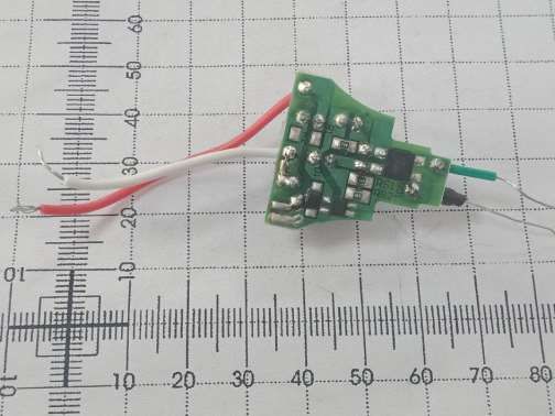
Page 32 of 34Photo 3: PCB view of G45-7-27/A12F/11
Photo 4: PCB view of G45-7-27/A12F/11
Test Report No.: EFSH19010936-IE-01-E01
Eurofins Product Testing Service (Shanghai) Co., Ltd
No. 395 West Jiangchang Road, Jing’an District, Shanghai, 200436, P.R. China
Page 33 of 34Photo 5: LED view of G45-7-27/A12F/11
Photo 6: LED view of G45-7-27/A12F/11
Test Report No.: EFSH19010936-IE-01-E01
Eurofins Product Testing Service (Shanghai) Co., Ltd
No. 395 West Jiangchang Road, Jing’an District, Shanghai, 200436, P.R. China
Page 34 of 34You can also read