EVE servo evaluation pcb - VERSION 2020.0 - SUBJECT TO PERMANENT DEVELOPMENT
←
→
Page content transcription
If your browser does not render page correctly, please read the page content below
EVE
                 servo evaluation pcb
                 VERSION 2020.0

                 SUBJECT TO PERMANENT DEVELOPMENT

Piratelogic EVE 2020.0 Manual 05/03/2022@07:37:22   Page 1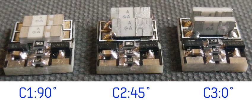
Contents
Before you start ....................................................................................................................................................................................................................... 3
      Prerequisites..........................................................................................................................................................................................................................................................................................................3
      Warranty / Disclaimer.......................................................................................................................................................................................................................................................................................3
      Availability ...............................................................................................................................................................................................................................................................................................................3
      Copyright...................................................................................................................................................................................................................................................................................................................3
      Design scope............................................................................................................................................................................................................................................................................................................3
      Bill of materials......................................................................................................................................................................................................................................................................................................4
      Schematic description......................................................................................................................................................................................................................................................................................5
            Line buffer.......................................................................................................................................................................................................................................................................................................5
            4th order high pass...................................................................................................................................................................................................................................................................................5
            PXE input buffer...........................................................................................................................................................................................................................................................................................5
            Loop Mixer.......................................................................................................................................................................................................................................................................................................6
            Limiter...............................................................................................................................................................................................................................................................................................................6
            Power..................................................................................................................................................................................................................................................................................................................6
            Improvements over EVE version 2018:........................................................................................................................................................................................................................................6
Main design considerations................................................................................................................................................................................................ 7
      Servo loop gain.......................................................................................................................................................................................................................................................................................................7
      Enclosure parameters......................................................................................................................................................................................................................................................................................8
      Low Pass Filter.......................................................................................................................................................................................................................................................................................................8
      Crossover points..................................................................................................................................................................................................................................................................................................9
      Rumble High Pass Filter....................................................................................................................................................................................................................................................................................9
      Accelerometer settings................................................................................................................................................................................................................................................................................10
          Bias....................................................................................................................................................................................................................................................................................................................10
          Gain...................................................................................................................................................................................................................................................................................................................10
          Highpass filter ..........................................................................................................................................................................................................................................................................................10
          Lowpass filter............................................................................................................................................................................................................................................................................................10
Configuring the Servo Feedback Loop......................................................................................................................................................................... 11
      DIYaudio test case............................................................................................................................................................................................................................................................................................11
      Basics........................................................................................................................................................................................................................................................................................................................11
      Example ScanSpeak ..........................................................................................................................................................................................................................................................................................12
          Free air response....................................................................................................................................................................................................................................................................................12
          Closed box response..............................................................................................................................................................................................................................................................................12
      Loop phase.............................................................................................................................................................................................................................................................................................................13
      Loop bandwidth...................................................................................................................................................................................................................................................................................................13
      Amplifier bandwidth.........................................................................................................................................................................................................................................................................................13
Building EVE ............................................................................................................................................................................................................................. 14
      Power requirements........................................................................................................................................................................................................................................................................................14
      Choosing Components....................................................................................................................................................................................................................................................................................14
      Onboard Regulators.........................................................................................................................................................................................................................................................................................14
PCB Layout ............................................................................................................................................................................................................................... 15
      Top layer names..................................................................................................................................................................................................................................................................................................15
      Bottom layer - names.....................................................................................................................................................................................................................................................................................16
      Bottom layer - values.....................................................................................................................................................................................................................................................................................17
      PCB circuit..............................................................................................................................................................................................................................................................................................................18
Driver Selection..................................................................................................................................................................................................................... 19
      Overall design considerations..................................................................................................................................................................................................................................................................19
      Main selection criteria...................................................................................................................................................................................................................................................................................19
Accelerometer Selection.................................................................................................................................................................................................... 20
      The original Philips MFB sensor...............................................................................................................................................................................................................................................................20
      Measurement specialities ACH-01.........................................................................................................................................................................................................................................................20
      Piratelogic Sensors.........................................................................................................................................................................................................................................................................................21
      Starbass ClingOn................................................................................................................................................................................................................................................................................................21
      Starbass Stripper..............................................................................................................................................................................................................................................................................................21
      StarBass 26 ...........................................................................................................................................................................................................................................................................................................21
      StarBass 54............................................................................................................................................................................................................................................................................................................21
      ClingOn variants C1, C2, C3..........................................................................................................................................................................................................................................................................22
Addendum.................................................................................................................................................................................................................................. 23
      Errata.........................................................................................................................................................................................................................................................................................................................23
      Document history..............................................................................................................................................................................................................................................................................................23

      About the author................................................................................................................................................................................................................................................................................................24

 Piratelogic EVE 2020.0 Manual 05/03/2022@07:37:22                                                                                                                                                                                                                                                               Page 2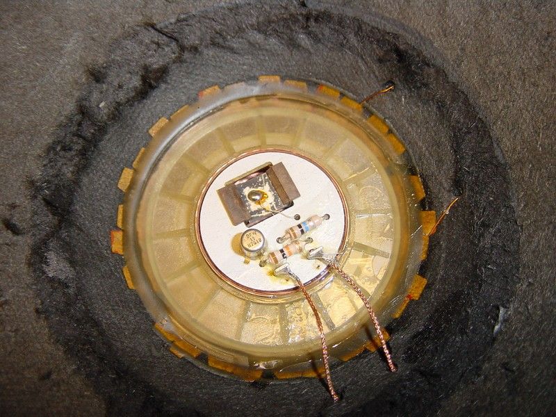
Before you start ....
        Thank you for purchasing the EVE pcb, please note this manual is subject to permanent development so
        expect grammar & spell checks, corrections and improvements, read the ERRATA section before building EVE !!

Prerequisites
        In order to successfully assemble the pcb the following prerequisites are needed.
        ◦    ESD safe working environment : EVE contains ESD sensitive jFet devices, please adhere to guidelines for
             safe handling of ESD sensitive components during assembly of the sensors.
        ◦    SMD soldering station : the EVE design uses surface mount technology and requires handling and use of
             an appropriate soldering station to avoid thermal damage to the used parts when soldered onto the PCB.

Warranty / Disclaimer
        Although this pcb has been developed with lots of love, tenderness and devotion and has been tested with
        numerous MFB enclosures it is subject to constant research and development and as such no guarantees
        and/or warranties can be given for the correct / optimal / failure free working of the module. No
        responsibility is taken for any damage resulting from the use of this module.

        Designing & building servo drive systems like described in this manual requires a
        thorough understanding of and working experience with the underlying electronics. An
        engineering degree and experience with component level board repair is strongly advised.
        This is NO starter project !!!!

Availability
        Bare EVE printed circuit boards without components are available for 15 euro a piece by sending an email to
        chris*nospam*piratelogic.nl – replace *nospam* with the standard @. At the time of writing pricing for a smd
        prepopulated pcb are being negotiated and will appear here in future manual updates. Pricing excludes VAT
        and shipment.

Copyright
        The EVE circuit design is free for use both for hobby as well commercially.

Design scope
        Back in 2017 EVE got originally developed as a quick and dirty solution to add servo bass functionality to an
        ADAM A7 monitor in conjunction with a StarBass IV accelerometer equipped woofer. EVE 2020.0 basically
        follows an identical setup with the quick and dirty parts removed and has been optimized using user input to
        improve both its performance as well as its ease of implementation.

                                                                                 MAY THE MUSIC PASSING THROUGH THIS DEVICE
                                                                             SOMEHOW HELP TO BRING JUST A LITTLE MORE PEACE
                                                                                                    TO THIS TROUBLED WORLD

Piratelogic EVE 2020.0 Manual 05/03/2022@07:37:22                                                                 Page 3
Bill of materials
        The parts listed below are surface mount devices, the schematic parts listed Cx and Rx are through-hole
        components which values are setup dependend. The LCSC identifiers can be used with
        https://jlcpcb.com/parts .

      Pa rt   Va lue         Pa c k a ge         D es c ription     L CSC           MO U SE R                  MPN
      78XX      7812           SOT89-3       Voltage stabilizer    C8615                                    CJ78L12
      79XX      7912           SOT89-3       Voltage stabilizer    C8626                                    CJ79L12
        C17     100n             C0805          SMD capacitor     C49678                          CC0805KRX7R9BB104
        C18     100n             C0805          SMD capacitor     C49678                          CC0805KRX7R9BB104
        C19     100n             C0805          SMD capacitor     C49678                          CC0805KRX7R9BB104
         C2      10n             C0805          SMD capacitor      C1710                           CL21B103KBANNNC
        C20     100n             C0805          SMD capacitor     C49678                          CC0805KRX7R9BB104
        C21     100n             C0805          SMD capacitor     C49678                          CC0805KRX7R9BB104
        C22     100n             C0805          SMD capacitor     C49678                          CC0805KRX7R9BB104
         C3    10-16             SMC_A          SMD capacitor      C7171                             TAJA106K016RNJ
         C7      10n             C0805          SMD capacitor      C1710                           CL21B103KBANNNC
         C9    10-16             SMC_A          SMD capacitor      C7171                             TAJA106K016RNJ
        IC1     5532               SO08      AUDIO AMPLIFIER       C7426                                   NE5532DR
        IC2     5532               SO08      AUDIO AMPLIFIER       C7426                                   NE5532DR
        IC3     5532               SO08      AUDIO AMPLIFIER       C7426                                   NE5532DR
        IC4     5532               SO08      AUDIO AMPLIFIER       C7426                                   NE5532DR
       LED-              CHIP-LED0805                       LED   C84256     FC-2012HRK-620D
      LED+               CHIP-LED0805                       LED   C84256     FC-2012HRK-620D
 LINE.GAIN        5K               B25P       POTENTIOMETER                 652-3362P-1-502LF
  PXE.BIAS        5K               B25P       POTENTIOMETER                 652-3362P-1-502LF
  PXE.GAIN        5K               B25P       POTENTIOMETER                 652-3362P-1-502LF
         R1     1501           R0805D             SMD resistor     C4310                            0805W8F1501T5E
        R11     1001           R0805D             SMD resistor    C17513                            0805W8F1001T5E
        R12     1002           R0805D             SMD resistor    C17414                            0805W8F1002T5E
        R13     1003           R0805D             SMD resistor    C17407                            0805W8F1003T5E
        R14     4702           R0805D             SMD resistor    C17713                            0805W8F4702T5E
        R15     1003           R0805D             SMD resistor    C17407                            0805W8F1003T5E
        R17     1001           R0805D             SMD resistor    C17513                            0805W8F1001T5E
        R19     1003           R0805D             SMD resistor    C17407                            0805W8F1003T5E
         R2     4702           R0805D             SMD resistor    C17713                            0805W8F4702T5E
        R20     1001           R0805D             SMD resistor    C17513                            0805W8F1001T5E
        R23     680R           R0805D             SMD resistor    C17798                            0805W8F6800T5E
        R25     1002           R0805D             SMD resistor    C17414                            0805W8F1002T5E
        R26     1002           R0805D             SMD resistor    C17414                            0805W8F1002T5E
        R29     1002           R0805D             SMD resistor    C17414                            0805W8F1002T5E
         R3     1001           R0805D             SMD resistor    C17513                            0805W8F1001T5E
        R30     1002           R0805D             SMD resistor    C17414                            0805W8F1002T5E
        R31     680R           R0805D             SMD resistor    C17798                            0805W8F6800T5E
        R32     680R           R0805D             SMD resistor    C17798                            0805W8F6800T5E
         R4     4701           R0805D             SMD resistor    C17673                            0805W8F4701T5E
         R6     4701           R0805D             SMD resistor    C17673                            0805W8F4701T5E
         R8     1001           R0805D             SMD resistor    C17513                            0805W8F1001T5E
         R9     1001           R0805D             SMD resistor    C17513                            0805W8F1001T5E
         T1    BC849             SOT23        NPN TRANSISTOR                  863-BC849CLT1G
         T2    BCV62          SOT143B       PNP current mirror               726-BCV62CE6327

Piratelogic EVE 2020.0 Manual 05/03/2022@07:37:22                                                            Page 4
Schematic description

        Line buffer
        The line buffer circuitry performs the following functions:
             •    The incoming audio signal arrives at LINE.IN where passes DC blocking capacitor C1 which together
                  with R2 and the input resistance of the 5532 - typically 300K – forms a 1 st order high pass set at
                  3.9hz.
             •    To minimize EVE's rf input susceptibility the lowpass filter R1,C2 is used, with C2=10n the LPF is set
                  at 10Khz. To avoid microphonics make sure to use a NP0 for C2 !
             •    Depending on your setup and power amplifier gain setting the EVE gain can be set between 2.6 and
                  11x with LINE.GAIN to adapt for use with to low gain final stages.

        4th order high pass
        The bandwith for the incoming line buffer signal is set by the 4 th order HPF build around IC1b and IC4b and
        the 2nd order LPF around IC4a.

        PXE input buffer
        The pxe input buffer processes the incoming accelerometer current signal and performs the following
        functions:
             •   The accelerometer current souce signal enters EVE at PXE.IN where it passes rf filter R9,C7 which
                 corner freqency is set to 7234 hz. To avoid microphonics make sure to use a NP0 for C7 !
             •   To adapt for jFet Vgs variations EVE allows the accelerometer bias voltage set for optimal linear
                 operation by setting PXE.BIAS voltage for T1, the standard StarBass bias voltage is 6V.
             •   The output of the current mirror T2 arrives at IC2a which allows phase invertion of the
                 accelerometer signal. Sensor signal gain and low pass is provided by IC3a, for measurement
                 purposes the accelerometer signal is made available via PXE.OUT. Use the OPENLOOP jumper to
                 perform open/closed loop measurements.

Piratelogic EVE 2020.0 Manual 05/03/2022@07:37:22                                                                 Page 5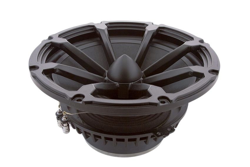
Loop Mixer
        The buffered, amplified and lowpassed StarBass signal arrives at IC3b where it is summed with the incoming
        audio signal via R26. C15, C16, R27 and R28 are used for setting loop gain and shaping.

        Limiter
        LED+ and – are used to limit the output of IC3b. Take care not to illuminate these externally to avoid the
        introduction of DC components into the feedback loop - thanks esl63@diyaudio for bringing this to my
        attention . The phase inverter IC2B is used to build the symmetric OUTPUT 3+ and 1-.

        Power
        7812 and 7912 are standard voltage regulators to allow EVE from being operated from the power amp rails,
        Eve's current draw is 40mA max, use R33 and R34 to bleed of excessive rails (regulator inputs are max +/-
        35V).

        Improvements over EVE version 2018:
             •   Input buffer

             •   Low noise pxe buffer with adjustable accelerometer bias voltage

             •   Through-hole loop shaping / filter parts & rails bleeders

             •   Max rails +/- 60V

             •   Open/closed loop mode switch

             •   led loop limiter

             •   Symmetric line out

             •   ne5532 opamps

             •   50x50 mm pcb size.

             •   JST headers

Piratelogic EVE 2020.0 Manual 05/03/2022@07:37:22                                                                Page 6
Main design considerations
        Being designed as a generic mfb correction module EVE supports a wide variety of driver, enclosure and
        loopgain choices. Because of this generic setup it is not possible to provide a common set of component
        values, to assist the user with making educated choices the following information is given. Servo / Motional
        feedback does not work with Helmholtz resonator based enclosures such as bass reflex boxes.

Servo loop gain
        EVE has been designed to offer a theoretical maximum servo loopgain of 20dB, refer to below graph for the
        relation between servo loopgain and a Q0.7 enclosure frequency response. Servo loopgain determines:
             •   The F3mfb, the higher the amount of gain the lower the resulting F3mfb will be.
             •   Maximum SPL, the 'extra' energy is rerouted to low extension.
             •   The amount of second and third harmonics supression available .

Piratelogic EVE 2020.0 Manual 05/03/2022@07:37:22                                                              Page 7
Enclosure parameters
        The first step is to set the low frequency pole for your mfb box F3mfb equal to the driver physical resonance
        frequency F3driver or higher, choosing values below F3driver will severely limit driver efficiency due to
        usage outside it's physical limits.
        The second step is to choose an enclosure volume using the standard closed box design formulas combined
        with the driver T&S parameters – to ease down on the involved math use a program like WinISD. Start with an
        enclosure Q of 0.7. As displayed above 12dB MFB loopgain allows you to split F3box in half so if the desired
        lower frequency pole of your finished box F3mfb is 60hz the chosen F3box should be 120hz or lower.
                                                                                       Example WINISD response plot for a
                                                                                       driver with a Fc of 60hz mounted in a
                                                                                       sealed Q=0.7 enclosure with a natural
                                                                                       Fbox of 120hz which is moved down to
                                                                                       Fmfb of 60hz.

                                                                                       Keep in mind that the higher
                                                                                       Qbox is chosen (= smaller box)
                                                                                       the harder the driver will need
                                                                                       to work to reach the required
                                                                                       excursion, as such one is
                                                                                       discouraged from using Qbox
                                                                                       values above 1 as it will limit
                                                                                       system efficiency and SPL.

Low Pass Filter
        The 3rd step is to decide on a low pass filter frequency -
        Flpf - using the drivers datasheet as reference. EVE's
        onboard lowpass filter follows a 2nd order Sallen Key
        setup, as such it is advised to choose Flpf at least 1
        octave away from the first occurrence of cone breakup.
        In the example on the right cone breakup occurs in the
        red region onwards 2500hz making 1250hz or lower a
        valid choice for Flpf
        For mfb to work best the driver cone movement
        needs to be pistonic in the area your loop is
        active in – voicecoil movement must mimic the
        cone without any partial vibrations like shown for
        the guitar speaker image (courtesy
        https://www.premierguitar.com) on the right.

        Without pistonic movement the correction signal
        will contain distortions that will mess up your
        control loop. None pistonic movement, also called
        cone breakup, introduces partial distortions
        which are not 'heard' by the accelerometer and
        thus not covered by the feedbackloop.

Piratelogic EVE 2020.0 Manual 05/03/2022@07:37:22                                                                  Page 8
Crossover points
        Using F3mfb and Flpf and F3box the component values for the desired crossover points can be calculated. The
        blue curve represents F3mfb and the green curve Flpf. These values were calculated using http://sim.okawa-
        denshi.jp/en/OPstool.php for the lowpass and http://sim.okawa-denshi.jp/en/OPseikiHikeisan.htm for the
        highpass filters.

           4th
               order Rum b le filter I C1B, I C4B Q=0.5            2 nd order Lo wpass filter I C1C Q= 0.74
       C5,C6,C10,C11 (nF) R7,R10,R16,R18 (K) Frequency (hz)   R22,R24 (K) C14 (nF)     C13(nF) Frequency (hz)   C16 (nF)
              100                 15               106            2.2         47         100          1055      1n5
              100                 18                88            3.3         47         100           703      2n2
              220                 10                72            3.9         47         100           595      2n7
              220                 12                60            4.7         47         100           493      3n3
              220                 15                48            2.7        100         220           397      3n9
              220                 18                40            3.3        100         220           325      4n7
              220                 22                32            3.9        100         220           275      5n6
              220                 27                27            4.7        100         220           228      6n8
              220                 33                21            5.6        100         220           191      8n2

Rumble High Pass Filter
        When choosing values for the rumble hpf be aware of the fact that the servoloop will attempt to correct cone
        motion right down to the lower pole of the EVE circuit. So if the system is offered a 5hz signal from a wobbly
        recordplayer it will make the connected driver follow this signal no matter it's amplitude. In the oldskool
        days this was the reason why commercial amplifiers were often equipped with a so called “SubSonics” filter.
        Be careful not to set the rumble frequency too low, -3dB @ 10hz may look nice on your spec list but will
        severly stress your driver when connected to a 500 watt Class D amp. Perform a LF sweep before deciding on
        how low you want things to go and keep in mind that average electronic music starts at 20hz.
        In case EVE is to be used with existing active enclosures it's build-in rumble and lowpass filters may need
        disabling:
   •    Disabling the rumble filter : omit R7, R10, R16, R18 and replace C5, C6, C10, C11 with wire bridges.
   •    Disabling the lowpass filter : omit C13, C14 and replace R22, R24 with 0 ohm resistors.

Piratelogic EVE 2020.0 Manual 05/03/2022@07:37:22                                                                          Page 9
Accelerometer settings
        Bias
        All StarBass accelerometers use a jFet transistor as impedance transformer with the pxe sensor element
        connected between it's gate and source. To obtain linear operation the jFet is biased into its ohmic region by
        setting Vgs to 0Vdc and placing a resistor over the pxe element which itself behaves like a capacitor :

        image courtesy of https://www.industrial-electronics.com/electrnc-dvcs-9e_8.html

        To minimize StarBass distortion while maximizing it's output EVE2020 allows you to bias the pxe voltage
        between 4 and 8V using the PXE.BIAS potentiometer to accommodate for different Vgs voltages. For further
        information regarding jFet gate-source pinch off voltages see https://en.wikipedia.org/wiki/JFET

        Gain
        Acceleration sensor output is determined both by its sensitivity in mV/G as well as the drivers linear cone
        excursion - to reproduce a certain SPL a small diameter driver will need to perform larger excursions then a
        large diameter driver, as such the accelerometer output is depended on the driver cone diameter. Longstroke
        drivers with a high Xmax will typically exhibit a relative high signal output when compared to standard
        drivers. To accommodate for this ajust PXE.GAIN which sets the gain for the incoming accelerometer signal.

        Highpass filter
        To avoid problems caused by the difference between the mirror output and opamp input DC levels a capacitor
        C8 was added to the circuit. The lower pole for the accelerometer signal Fpxe.low determines the low end
        loop stability and should be chosen at least at one tenth of F3mfb, too high values in respect to F3mfb will
        cause phase shift induced LF oscillations. Starting values for C8 and R19 are 680n and 120K setting Fpxe.low
        at 2hz. See also the topic Amplifier bandwidth in the chapter Configuring the Servo Feedback Loop.

        Lowpass filter
        The high pole for the accelerometer signal – Fpxe.high – avoids driver breakup from entering the summation
        signal at IC3b. As a starting value half the low pass filter frequency Flpf should be used when calculating C12.

         C12                            Sensor cut-off frequency C12                       Sensor cut-off frequency
         2n2                            7200 hz                                     8n2    1940 hz

         3n3                            4822 hz                                     10n    1591 hz

         3n9                            4080 hz                                     15n    1061 hz

         4n7                            3386 hz                                     22n    723 hz

         5n6                            2842 hz                                     33n    482 hz

         6n8                            2340 hz                                     47n    338 hz

Piratelogic EVE 2020.0 Manual 05/03/2022@07:37:27                                                                     Page 10
Configuring the Servo Feedback Loop
With the main design parameters being set the next step is to tune the servo loop to match a chosen
enclosure and driver combination. Like any other feedback system it's feedback loop needs to perform within
certain parameters to ensure stable operation while maximizing sonic performance. The EVE loop mixer
design incorporates all parts needed to build a well tuned feedback loop.
DIYaudio test case
It is outside the scope of this document to fully cover the physical and electronical ins & outs of the tuning
process but I have attempted to collect the most important parts, for use-case information please refer to
the excellent thread by Rob Campbell MFB for ACI SV12 Drivers using Piratelogic Electronics on
DIYAUDIO available here:
https://www.diyaudio.com/forums/subwoofers/336070-mfb-aci-sv12-drivers-using-piratelogic-electronics.html
Basics
From a physics perspective a closed loudspeaker enclosure behaves like a spring-mass system, with its
response transitioning from compliance dependant – controlled by the spider & surround - to purely mass
controlled with F3box as the turning point inbetween. From an electronical perspective it behaves similar to
a standard second order high pass filter with the corresponding 12 dB/Oct slope and 180º phase shift at
F3box.
In order to do it's magic a well tuned MFB system will not only compensate for the -12dB slope below F3box
but also introduce a phase shift to compensate for the natural 180º phase shift at F3box and thereby
maintain phase neutral operation. Without the latter loop stability is in danger resulting in positive feedback
making the loop oscillate at a frequency below F3box. Depending on available power and F3box this may result
in very low – un hearable ! - freqency instabilities which ultimately will overheat and damage the driver
motor system.
A well designed servo system will not only maintain shape between it's in en output but also keep them in
phase.
Piratelogic EVE 2020.0 Manual 05/03/2022@07:37:27 Page 11Example ScanSpeak
Free air response
With help of the excellent online
loudspeaker database available at
http://www.loudspeakerdatabase.com/
the following simulation was made
for a Scan-Speak 15W/8424G00.
Shown on the right is the drivers
free air impedance/phase curve.
Note the 120 degree phase shift at
45hz, the drivers free air resonance
frequency F3driver. Using this
driver TS parameters as a reference
the choosen F3mfb frequency would
equal 45hz or higher.
Closed box response
The graph on the right shows the
impedance/phase plot for the driver
mounted into a 3.7 Little/One closed
box, both F3box and it's accompaning
phase shift have shifted towards 101
hz .
To assure stable operation the F3box
phase shift should be compensated
by the stepfilter R27 and C15.
Piratelogic EVE 2020.0 Manual 05/03/2022@07:37:27 Page 12Loop phase
Please note EVE introduces a 180 degree phase shift between it's LINE.IN and OUTPUT.3 signal due to the
inverting nature of the summation opamp IC3b. EVE2020 is fitted with an extra phase invertor to allow the
module to be directly connected to power amplifiers with a symmetric input. To invert the phase operation
simply swap the 1 and 3 output pins to your amplifier. When your amp is equipped with a single async input
connect it to either pin 1 or 3 of the OUTPUT. In either case use the PXE.PHASE jumper to maintain the negative
feedback loop.
Loop bandwidth
C16 limits the upper bandwidth of the mfb loop and it's value should be set to match the lowpass filter setting
for IC4a. Please refer to 2nd order Lowpass filter IC1C table on page 8 for C16 values.
Amplifier bandwidth
When using EVE with third party power
amplifiers make sure their lower
bandwidth pole starts sufficiently low,
a too high value may negatively effect
loop stability due to the introduction
of LF phaseshifts. As a rule of thumb
make sure your amplifier lower F3 pole
is at least 1 tenth of your desired
F3mfb.
As an example please find the following
points of attention in the LM3886
based setup on the right:
• The amp input RC 10uF/75K, F
corner for this combination is
0,21 hz allowing for a F3mfb of
2,1 hz and above.
• The amp feedback loop RC
10uF/1K , F corner for this
combination is 16 hz allowing
for a F3mfb of 160 hz and above. For a F3mfb of 20hz up the capacitor to at least 100uF.
• Some older designs use an dc blocking output capacitor in series with the driver, for a F3mfb of 20hz
in combination with a 4 ohm driver use an output capacitor of at least 20.000uF.
Piratelogic EVE 2020.0 Manual 05/03/2022@07:37:27 Page 13Building EVE
Power requirements
The EVE current draw at +/- 12V is 40mA max.. The
onboard 78L12 and 79L12 regulators allow EVE to be
powered directly from a maximum rail voltage of +/-
35V without the use of the rails bleeders R33 and R34
which can be ommitted using wire bridges. When
powering EVE from higher voltage rails use R33 and
R34 to bleed of the extra voltage. The shapes for R33
and 34 allow usage of 1 Watt resistors which with a
currentdraw of 40mA and a value of 680 ohms allow for
a maximum voltage drop of 25V resulting in a
maximum admissable rail voltage of +/- 60V.
Incase EVE is to be used as a standalone module please
provide for a symmetrical psu capable of delivering
+/- 15V @ 80mA minimum such as done by this kit:
https://www.tubeland.de/product_info.php?products_id=13:
Choosing Components
EVE's primary goal is to offer a bare bone proof of concept servo loop solution and has been designed with
cost effective readily available non-exotic parts in mind. The used 5532 opamps dates back to 1978 and by no
means represents the state of the art in opamp design. However since servo loops typically operate in the lf
domain it's specs are more then sufficient for the task at hand, refer to the 5532 datasheet for further
information.
Onboard Regulators
Contrary to EVE2018 the 2020 version uses the standard 78L12 and 79L12 regulators in a SOT89 package,
before ordering please verify the below indicated pin layouts are used.
Piratelogic EVE 2020.0 Manual 05/03/2022@07:37:27 Page 14PCB Layout
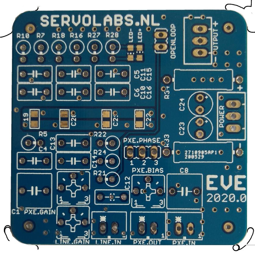
Top layer names
Please note EVE is currently sold as bare PCB only and as such does not contain any components .
Piratelogic EVE 2020.0 Manual 05/03/2022@07:37:27 Page 15Bottom layer - names Piratelogic EVE 2020.0 Manual 05/03/2022@07:37:28 Page 16
Bottom layer - values

Piratelogic EVE 2020.0 Manual 05/03/2022@07:37:28   Page 17
PCB circuit

Piratelogic EVE 2020.0 Manual 05/03/2022@07:37:29   Page 18
Driver Selection

Overall design considerations
        Designing a low note system starts with choosing main design parameters like sound presure level,
        dispersion pattern, power bandwidth etc, for the most of it designing a MFB system follows identical rules and
        logic with the exception of some important design considerations unique to MFB that need highlighting:
             •   As the feedback loop will attempt to mimic physical cone movement to amplifier input ported designs
                 exhibiting a helmholtz resonance will not work without extensive loop tuning.
             •   MFB exchanges acoustical power output for lownote extension, if it's purely SPL your after MFB
                 might not be your weapon of choice as the extra fundament comes at a price.
             •   Operating a driver / enclosure below F3box requires extra power to force cone movement to mimic
                 the incoming electrical waveform . The extra amplifier power has thermal consequences for the
                 driver motor system and requires extra care not to exceed thermal power handling and safe
                 operating areas, specially since closed cabinets lack motor cooling by natural convection.

Main selection criteria
        Selecting a driver for use with motional feedback systems requires attention to the following specific design
        details:
        Cone size / material : make sure the driver cone
        maintains pistonic motion in the area mfb will be active
        in. The larger the driver the harder it will be for it to
        maintain pistonic operation. For high SPL designs
        daisy chaining multiple smaller diameter drivers might
        yield better results then a single large one, small
        lightweight & sturdy cones are favourable over large
        and heavy ones.
        High BL: to maximise mfb control over the driver cone
        movement a strong motor system is required.
        High Xmax : depending on the desired power bandwidth
        and used cabinet Q the driver needs to linearly move as
        much air as possible.
        Low CMS : a too high value in combination with MFB will
        severely affect distortion figures due to the deformation of the surround caused by the cones pumping
        action . This is especially comes into play with Qbox designs above 0.7.
        Ventilated polepiece : to allow convection of heat away from the voice coil as quickly as possible. Note that
        since MFB required a closed cabinet the temperature inside the enclosure will be considerably higher
        compared to vented enclosures. Aluminium cones exhibit better heat transfer characteristics then carbon /
        non metalic models.
        High temp voicecoil former : usage of vintage – paper – voicecoil formers severely restrict the powerhandling.

        Driver on display : http://www.loudspeakerdatabase.com/VOLT/RV3143

Piratelogic EVE 2020.0 Manual 05/03/2022@07:37:29                                                              Page 19
Accelerometer Selection
Altough EVE can be tailored to work with a wide variety of accelerometers the best results are obtained in
conjunction with the Piratelogic StarBass sensors. Third party sensors might also work but have not been
tested extensively and might need additional tuning in order to perform well.
The original Philips MFB sensor
When planning on using a Philips MFB woofer equiped
with the original BFW11 sensor like displayed – the
picture shows the sensor mounted in a AD12100/MFB
as used with their famous 545 enclosure – note you
will have to compensate for the combination of their
low capacitance of the used pxe element (1n5) and 10M
brown – black – blue gate resistor resulting in a lower
pole of 10.61hz. See the sensor circuit below for more
info. Without loop compensation the resulting phase
shift might introduce subsonic instabilities below
100hz. For more information google the 545 service
manual and lookup the circuitry around TS549 for
further details. All StarBass sensors have their lower
pole sit at 2.7hz making them suitable for use from
27hz and upwards .
Measurement specialities ACH-01
When planning on using the ACH-01 accelerometer
please note the following:
• Although shielded from above the sensors
ceramic baseplate is not shielded and will
pickup noise if left un treated.
• When mounted on a carrier construct make
sure to take precautions against the pickup
of base strain induced non axial information.
Piratelogic EVE 2020.0 Manual 05/03/2022@07:37:30 Page 20Piratelogic Sensors
All StarBass accelerometers feature a low distortion design with a current output, shielded against EMI, RF
and static electricity. For pricing and availability visit piratelogic.nl . Piratelogic offers accelerometer
products for a wide variety of low note drivers ranging from small 0.8inch VC home use to large 4 inch pro
models, drivers using an extended polepiece for BL over Xmax linearisation and low profile drivers. To assist
the user in the selection process the following information is given.
Starbass ClingOn
Low MMS 2P motional feedback accelerometer for use with polepiece
extended motors, designed to be vertically mounted against the outer
voicecoil former. Available with 3 primary axis, see Motor assembly
variants for more info.
Current status : beta 2, samples available.
Starbass Stripper
Low MMS 2P motional feedback accelerometer for use with voicecoil
diameters between 20 and 25 mm, designed to be mounted horizontally
inside the voicecoil former.
Current status : beta 1, samples available.
StarBass 26
Low MMS 2P motional feedback accelerometer for use with voicecoil
diameters between 25 and 26 mm, designed to be mounted horizontally
inside the voicecoil former. Sold in pairs of two with accompaning
connector strips in a single breakout pcb.
Current status: backorder.
StarBass 54
Low MMS 2P motional feedback accelerometer for use with voicecoil
diameters between 30 and 54 mm or 1.25" - 2", designed to be mounted
inside the voicecoil former.
Current status: production version 5, in stock.
Piratelogic EVE 2020.0 Manual 05/03/2022@07:37:30 Page 21ClingOn variants C1, C2, C3
Accelerometer and placement choices for the most
used driver motor structure:
1. StarBass 54 requires disassembly of the dustcap, best
quality feedback signal for VC diameters between 1.5
and 2 inch. Balanced loading, between 3 and 4 gramms
addition to MMS.
2. ClingOn C1 with 90°primary axis, no dustcap
disassembly required, usability depends on Vctravel,
risk of unbalanced loading with low MMS cones.
3. ClingOn C2 with 45°primary axis, no dustcap
disassembly required, Risk of unbalanced loading with
low MMS cones, risk of cone breakup information pickup.
Accelerometer and placement choices for extended
polepiece motor structures:
Due to the used of an extended polepiece the use of a
StarBass 54 is ruled out. This setup has succesfully been
tested with Peerless XLS10 and WaveCor SW023 chassis.
1. ClingOn C1 with 90°primary axis, no dustcap
disassembly required, usability depends on Vctravel,
risk of unbalanced loading with low MMS cones.
2. ClingOn C2 with 45° primary axis, no dustcap
disassembly required, Risk of unbalanced loading with
low MMS cones, risk of cone breakup information pickup.
Accelerometer and placement choices for flat panel
motor structures:
ClingOn C3 with 0° primary axis, usage of ClingON
accelerometers with this type of motor structure has
not been tested but is given in response to a DIYaudio
post by Lejonkungen investigating it's use with a
TangBand w3-1876 .
When ordering ClingOn accelerometers please
indicated the desired primary axis,
• ClingOn C1 : 90°
• ClingOn C2: 45°
• ClingOn C3: 0°
Please note that all StarBass models register axial acceleration info only with complete absence of non axial
information caused by VC deformation, while at the same time don't suffer from transformation effects such
as the case with pickup-coil based systems.
Piratelogic EVE 2020.0 Manual 05/03/2022@07:37:31 Page 22Addendum
Errata
Errata #1, missing
trace
Please note the EVE2020.0
pcb is missing a bottom trace
resulting in the + output not
being connected, please add
a small wire between the
solder points as shown in the
image on the right to fix this.
Document history
Prior to starting work please check if the date & time stamp at the footer of this page corresponds with the
one in the online version by clicking the Piratelogic EVE 2020.0 Manual link in the footer of this document.
14/06/2020 Initial version by CC 19/03/2021 Added warning for photovoltaic effect of limiter leds (thx esl63)
15/06/2020 Updated schematic captions by CC 16/12/2021 Added warning on microphonics for C2,9
28/06/2020 Added Accelerometer Selection information 05/02/22 Added functional info on C8.
08/07/2020 Updated BOM & schematics 21/02/22 Added external psu info (thx Thoren)
05/08/2020 Added engineering degree requirment 05/03/22 Fuck Putin & added 3rd party sensor info
20/09/2020 Added Erata #1, PCB price drop to 15 euro.
23/09/2020 Added ClingOn C1/C2/C3 primary axis info.
21/01/2021 Updated Erata #1 PCB image
08/02/2021 Spelling / Wording
Piratelogic EVE 2020.0 Manual 05/03/2022@07:37:33 Page 23About the author
Ever since I first was subjected to the Motional Feedback bass
reproduction at age eleven I'm amongst the evangelists for this truly
groundbreaking loudspeaker technology. It's sheer impact on low
note sonics, it's power and control will remain with anyone fortunate
enough to have witnessed it.
During research into electro & mechatronics, the science behind
motional feedback, it quickly became obvious that all starts with
obtaining a high resolution and error free control signal, as such
focus was shifted towards development of the Piratelogic StarBass
accelerometers. A turning point was the discovery of an industrial
shock sensor paving the way for a new breed of high quality servo
designs. Being a hands-on guy I prefer building things using an
educated trial and error approach , simulations and formula's are great but witnessing things react the way
they do is gold. Building well performing MFB systems isn't an easy thing to do but using EVE with an StarBass
equipped driver allows you to skip the hardest parts.
Created from an affordable budget the Little/One 2 way system is my proof of concept that MFB is still very
much alive and kicking and it's successor, the Grown/Up 3 way is on its way to create even more fuzz. The EVE
2020 design incorporates lessons learned sofar, its opensource design is my gift to you, ready to be pirated
world wide. Hence the logic in Piratelogic …. now GO! use EVE to learn about MFB, use it to create your own
servo drive low note system and put motional feedback back where it belongs : into the spotlights among the
top low frequency enclosures out there.
Stay safe & keep away from audiophile cabling & fuses discussions
Greetings from Amsterdam,
Youtube channel : https://www.youtube.com/user/motorindo
Chris Camphuisen
Piratelogic EVE 2020.0 Manual 05/03/2022@07:37:34 Page 24You can also read