The ID.4 New Model Overview - Tablet Format Self Study Program 891213 - NHTSA
←
→
Page content transcription
If your browser does not render page correctly, please read the page content below
Self Study Program 891213

The ID.4 New Model Overview
Tablet Format
Volkswagen Group of America, LLC
Volkswagen Academy
Published in U.S.A.
3/2021

Course Number SSP 891213

©2020 Volkswagen Group of America, LLC.

All rights reserved. All information contained in this manual is based on the latest information available at the time of publishing and is subject to the
copyright and other intellectual property rights of Volkswagen Group of America, LLC., its affiliated companies and its licensors. All rights are reserved to make
changes at any time without notice. No part of this document may be reproduced, stored in a retrieval system, or transmitted in any form or by any means,
electronic, mechanical, photocopying, recording or otherwise, nor may these materials be modified or reposted to other sites without the prior expressed
written permission of the publisher.

All requests for permission to copy and redistribute information should be referred to Volkswagen Group of America, LLC.

Always check Technical Bulletins and the latest electronic repair information for information that may supersede any information included in this booklet.

Trademarks: All brand names and product names used in this manual are trade names, service marks, trademarks, or registered trademarks; and are the
property of their respective owners.
Table of Contents

           Introduction. . . . . . . . . . . . . . . . . . . . . . . . . . . . . . . . . . . . . . . . . . . . . . . . . . . . . . . . . . . . . . . . . . 1
           Body. . . . . . . . . . . . . . . . . . . . . . . . . . . . . . . . . . . . . . . . . . . . . . . . . . . . . . . . . . . . . . . . . . . . . . . . 6
           High-voltage Systems. . . . . . . . . . . . . . . . . . . . . . . . . . . . . . . . . . . . . . . . . . . . . . . . . . . . . . . . 13
           Power Transmission. . . . . . . . . . . . . . . . . . . . . . . . . . . . . . . . . . . . . . . . . . . . . . . . . . . . . . . . . . 16
           Running Gear. . . . . . . . . . . . . . . . . . . . . . . . . . . . . . . . . . . . . . . . . . . . . . . . . . . . . . . . . . . . . . . . 20
           Driver Assist Systems. . . . . . . . . . . . . . . . . . . . . . . . . . . . . . . . . . . . . . . . . . . . . . . . . . . . . . . . . 21
           Climate Control. . . . . . . . . . . . . . . . . . . . . . . . . . . . . . . . . . . . . . . . . . . . . . . . . . . . . . . . . . . . . . 22
           Electrical System . . . . . . . . . . . . . . . . . . . . . . . . . . . . . . . . . . . . . . . . . . . . . . . . . . . . . . . . . . . . 31
           Infotainment. . . . . . . . . . . . . . . . . . . . . . . . . . . . . . . . . . . . . . . . . . . . . . . . . . . . . . . . . . . . . . . . 41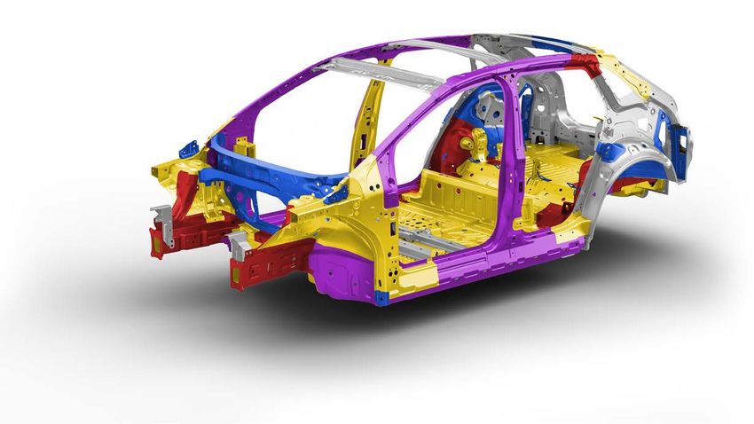
Introduction

The ID.4 - a Departure into a New Era
In the North American Region, the ID.4 launches a new defining model generation at Volkswagen.

It is an electric vehicle built on the new Modular Electric Drive Matrix (MEB), that networks with the internet, has digital display and control elements, natural
voice control and other pioneering technologies to signal the beginning of a new era.

Intelligent, innovative and sustainable – the ID.4

  1
Introduction

Production Sites

The Volkswagen ID.4 is being built at Zwickau and Chattanooga.

Zwickau is playing a key role with the start of production: for the first time, a large car factory has been completely re-equipped for electric mobility. In the
final expansion stage from 2021, the Zwickau plant will build six electric models for three Group brands with a volume of up to 330,000 vehicles per year. The
site is developing into Europe’s largest and most efficient electric car factory and is leading the way in the transformation of Volkswagen’s global production
network.

Production of the ID.4 will be coming to Chattanooga in 2022. To support this, Volkswagen is expanding it’s Chattanooga operations with a 564,000 square-
foot electric vehicle expansion and a 198,000 square foot battery pack assembly facility. This will solidify Volkswagen’s hub for electric vehicles in the region.
Along with increasing regional engineering capabilities, this step also supports the effort to localize all aspects of vehicle development and production.

  2
Introduction

Product Features of ID.4
The Innovative and striking product features are:

                                                                                      Five-link rear axle
                                        Disctinctive exterior lighting

                                                                                                                Rear drum brakes with
                                                                                                                Electromechanical Parking Brake
           Three-phase current drive in different                                                               EMPB
           battery power levels

  Second Generation                                                                                         Modular high-voltage battery
  Electromechanical Brake Booster

                                                                               New Keyless Access (KESSY)
                                        Single-pinion power steering, speed-   vehicle functions
                                        dependent

                       Equipment varies from country to country.

  3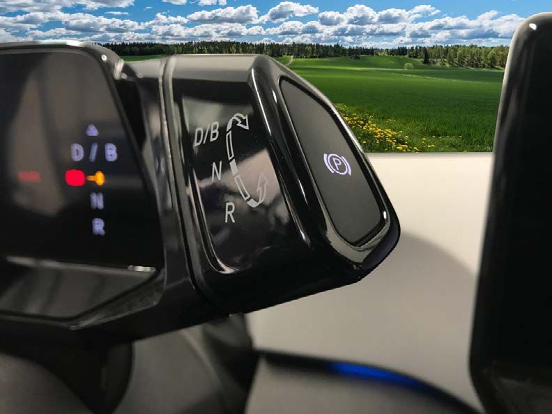
Introduction

Exterior
The exterior of the ID.4 has the following features:

• LED headlights
• Illuminated light strips in the front trim on the left and right of the front VW badge
• Panoramic glass sunroof (optional)
• 19” and 20” alloy wheel rims
• LED tail light clusters
• Light strip between the VW logo and the tail lights
• Composite rear wing above the rear glass

  4
Introduction

Interior
The interior of the ID.4 has the following features:

• ID.Light, an intuitive light strip in the front area of the dash panel. It indicates locking status, driver assist information,
  navigation system information, braking prompts and incoming phone calls
• Either 10 or 30-color ambient lighting across the dash panel, in the door handles and in the cell phone compartment in the
  center console
• Multifunction steering wheel with touch control
• 12” display and control panel with integrated temperature and volume adjustment
• 5.3” dash panel insert with integrated driving mode selector
• Pedals featuring “Play & Pause” design (1st Edition Only)
• 30.3 cubic feet of cargo area with the rear seat up

  5
Body

Technical Data
Exterior dimensions and weights

                                                                     63.5 in (1,612 mm)
                                                                                                               REPLACE WITH
                                                                                                                ID.4 IMAGE

                                                                                          61.6 in (1,565 mm)   62.5 in (1,587 mm)
     853 mm                 108.9 in (2,766 mm)          965 mm                            83 in (2,108 mm)     73 in (1,852 mm)
                            180.5 in (4,584 mm)

     Weight and additional information

      Gross vehicle weight rating                 5,644 - 6,019 lb
                                                  2,560 - 2,730 kg
      Curb weight according to DIN*               4,599 - 4,888 lb
                                                  2,068 - 2217 kg
      Turning radius                              33.5 - 38 ft
                                                  10.2 - 11.6 m
      Ground clearance                            6.4 in - 163 mm
      Drag coefficient**                          0.28 Cd
     * DIN German Institute for Standarization
     ** According to equipment

 6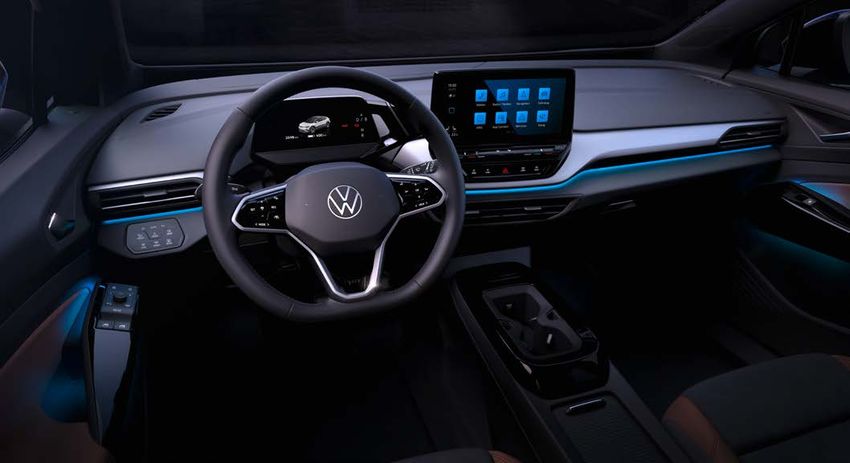
Body

Technical Data
Interior dimensions and capacities

                                                                                        85.4 in (2,170 mm)
                                                                        (753 mm) (681 mm)
                                                                                   26.8 in
                                     30.3 ft3

                                                                          29.7 in
                                                                                                               42.4 in
                                                                                                             (1077 mm)

                                                Volume and power

                                                Luggage compartment volume                                   30.3 ft3 (858 liters)
                                                Luggage compartment volume with rear seat                    64.2 ft3 (1817 liters)
                                                backrest folded down
                                                Through load width between wheel housing                     39.4 in (1001 mm)
                                                Weight of high-voltage battery                               1087 lb (493 kg)
                                                Nominal energy (net):                                        82 kWh
                                                Max. output front (optional)                                 107 hp (80 kW)
                                                Max. torque front (optional)                                 119.5 lb-ft (162 Nm)
                                                Max output rear                                              201 hp (150 kW)
                                                Max Torque Rear                                              228 lb-ft (310 Nm)

 7
Body
Body Structure Overview
The new strategy of the Modular Electric Drive Matrix (MEB) is based on the floorplan. The wheelbase is longer and the overhangs at the front and rear are
shorter compared with the MQB. The battery is bolted to the vehicle floor between the front and rear axles. A battery located on the vehicle floor provides a
lower center of gravity, more balanced weight distribution in the body and better driving dynamics.
The interior space is also greater because many components normally found in an internal-combustion engine vehicle have been removed, such as space for
the combustion engine, transmission, transmission tunnel, fuel tank and exhaust system. The electric drive motors are located directly on the axles, which
saves space and also lowers the center of gravity.
The front longitudinal members are connected directly
to the ultra-high strength hot formed footwell cross
member.
Front
Longitudinal
Member
Extruded InsertsBody
Body Structure
Extruded Profile
The battery is protected by the hot formed side members that have internal extruded aluminium inserts. These side members absorb side impact energy and
distributes it to other parts of the vehicle.
3-part Inner Sill Panel
(hot-formed)
Aluminium Insert
Aluminium Insert (extruded profile)
(extruded profile) Outer Side Member
(hot-formed)
9Body
Body Assembly
Rear Lid
The rear lid on the ID.4 has:
•
• New Volkswagen logo
• A one-piece rear lid with integrated spoiler on the upper sides
• Side spoilers (“aerodecks”) on the rear lid Third Brake Light
• Black side spoilers and upper spoiler area
• A trim panel under the spoiler that holds the third brake light
"Aerodeck" Side Spoilers
New Logo
10Body
Tensioning Spring
Body Assembly
LED Lighting
Door Handle
The door handle on the ID.4 is significantly different from other Volkswagen
vehicles. It is flush with the door panel. To open the vehicle, only a gentle
touch is needed to activate the microswitch in the handle. This microswitch
unlocks the lock, which opens the door.
If the vehicle does not have electrical power, mechanical manual operation
is possible. Using enough force the door handle can be moved upward,
actuating the door latch via Bowden cable. Release Sensor
If the vehicle loses electrical power when locked, a lock cylinder is located Mounting Anti-theft Panel
under a removable trim piece on the driver’s door handle. Bracket
Manual Release
Actuating Arm Rocker Switch
Slide Mechanism
Locking Element
Eccentric Locking Element
Locking Plate
(used to lock the door handle
into the mounting bracket)
11 Red indicates the starting position of the handle locking assembly.
Blue indicates when the door handle is in its locked and secure position.Safety Equipment
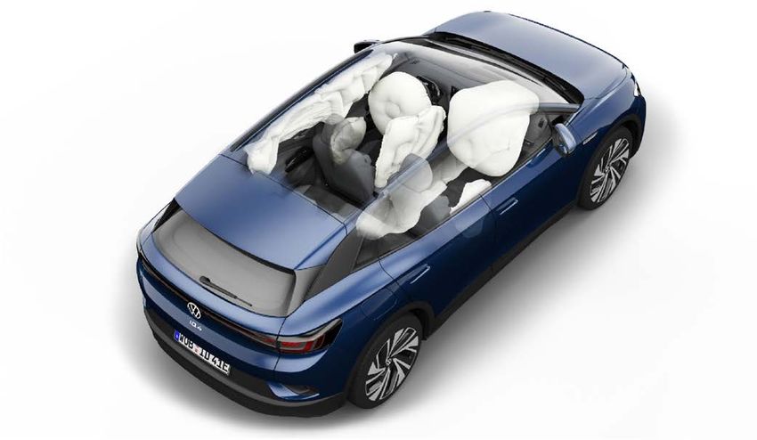
Occupant Protection
The ID.4 comes with the maximum range of safety features. Numerous assist
systems ensure the highest possible level of safety and comfort.
All ID.4 vehicles have the following standard features: Head Airbag Driver Airbag
• Driver and front passenger airbags
• Front side airbag
• Head airbags (curtain) front and rear
• Belt tensioners on front and outer rear seats
• Reversible belt tensioners with single-stage belt
force limiters at front
• Rear seat top tether
Active Safety:
• Multicollision Brake 2.0
• Front Assist with Pedestrian Monitoring
• PreCrash basic
• Emergency Assist
Side Airbag
The center airbag shown in this image is not for the North American market.
12High-Voltage System
Overview of High-Voltage Components
High-Voltage Battery
Charging Socket 1 UX4
Voltage Converter A19
Three-phase Current Drive VX54
Air Conditioning Compressor VX81 Power and Control ELectronics
for Electric Drive JX1
PTC Heater Element 3 Z132
High-Voltage Heater (PTC) ZX17 Charging Unit 1 for High-Voltage
(inside of cabin in air distribution box) Battery AX4
High-Voltage Battery 1 AX2
The following two pages have a summary of each component. It can be accessed by selecting the
hyperlinked text on this page or by scrolling to the next pages.
There is detailed information about the high-voltage
system in SSP 811213 The ID.4 High-Voltage System.
13High-Voltage System
A19 Voltage Converter provides the 12-volt AX2 High-voltage Battery 1 is a lithium-ion battery. This is located on the
electrical system with voltage and pre-charges the vehicle underbody. This placement provides a low center of gravity and
capacitor in the Power and Control Electronics for optimized weight distribution. The High-voltage Battery 1 AX2 supplies
Electric Drive. It serves as a second energy source. the electrical energy for driving and is offered in both a 62 and an 82 kWh
configuration. Only the 82 kWh battery will be available at launch.
AX4 Charging Unit 1 for High-Voltage Battery is 58 (62) kWh 77 (82) kWh
located in the rear of the ID.4. It converts the
alternating current from the charging connection
into a direct current for charging the high-voltage
battery.
VX81 Air Conditioning Compressor is integrated
into the high-voltage system. It is used for
heating both the interior and the high-voltage
battery.
JX1 Power and Control Electronics for
Electric Drive converts the customer's
power requests into electrical signals. The
power electronics control the three-phase
current drive. DC voltage from the high-
voltage battery is converted into a three-
phase AC voltage for acceleration.
Back to Overview Page
14High-Voltage System
UX4 High-Voltage Battery Charging
Socket 1 can charge the high-voltage
battery. Either AC or DC charging is
possible. Status lights indicate the
vehicle’s current charging status. Z132 PTC Heater Element 3 both heats the
coolant for the high-voltage battery and for
active heating.
It is controlled by the Battery Regulation
Control Unit J840 using LIN-bus
VX54 Three-phase Current Drive can drive the communication.
vehicle as an electric motor or charge the high-
voltage battery as an alternator.
The three-phase current drive is available in
ZX17 High-Voltage Heater (PTC) is a cabin air
two different output levels that are software-
heater and contains both the high-voltage
based. The basic level provides 201 hp heater (PTC) Z115 and the control module. It
(150 kW) and the performance level provides has an output of up to 6,000 watts and can be
302 hp (224 kW) regulated in three stages.
The air conditioning control module controls
this heater.
Back to Overview Page
15Transmission
One-speed Transmission 0MH
General Design
Oil Collector
The single-speed transmission 0MH is attached to the Three-phase Current Transmission Housing
Drive VX54 on the rear axle. When compared with the e-Golf transmission, it
is considerably more compact, lighter and durable. However, the transmission
design is very similar.
There is no longer a parking lock in the transmission. This function is
performed by the Electromechanical Parking Brake (EMPB).
The following parts are located in the transmission:
• Input shaft with gear Z1
• Output shaft with gears Z2 and Z3
• Differential with axle drive gear Z4
• Oil collector
The output shaft allows the overall ratio to be created in two steps (Z1 + Z2,
then Z3 + Z4). This creates a compact and lightweight design.
Input Shaft
with Gear 1
Output Shaft with the
Gears Z2 and Z3
Differential with Axle
Drive Gear Z4
16Transmission
One-speed Transmission 0MH
Technical Data
Workshop/Internal Designation One Speed Transmission 0MH/EQ310-1P
Gearbox code UMG (ID.4)
Number of gears 1
Transmission steps 2
Total: 11.53
Step 1: 2.957
Transmission ratios (Z1=23; Z2=68)
Step 2:3.9
(Z3=20; Z4=78)
Maximum input torque 310 Nm (229 lb/ft)
Maximum input speed 16,000 rpm
Total Weight 21.4 kg (47 lb)
0.81 + 0.1L / lifetime fill
Oil quantity/maintenance
(always check the Repair Manual for the latest information)
Input shafts splined connection
17Transmission
One-speed Transmission 0MH - Operation
Driving Mode Selection and Parking Brake
The driving mode is selected using the drive mode selector located on
the steering column switch module.
Driving Mode Selector EMPB Button E538
The Electromechanical Parking Brake (EMPB) is activated with the
EMPB Button E538. The button is connected directly to the ABS
Control Module J104.
Driving Mode Selector
When the driving mode selector is turned to select a gear, two detents
can be overcome in both directions of rotation. If it is turned one
detent upward, the forward gear D is selected. If it is turned again in
that direction, it switches from D to B and vice versa.
If the switch is turned one detent downward from this driving mode,
driving mode N will be activated. If it is turned past two pressure
points, R will be immediately selected.
If, when turning upward, two pressure points are passed at once, the
D/B driving mode previously deselected will be active again. This fast
change allows the vehicle to be rocked free in case it is stuck.
When released, the driving mode selector will always spring back to its
initial position.
The EMPB is engaged by pressing the button E538 or by using the Auto
P function.
Steering Column Switch Module with J527
18Transmission
One-speed Transmission 0MH - Operation
Driving Mode Display
Transmission Range Display is part of the Driver Information System Control
Module with Display Unit J1254.
The active driving mode is highlighted in amber. Inactive driving modes are
white.
D– Continuous setting for forward travel – The electric drive is in the
normal program (automatic energy recovery is enabled when ECO
assist system is activated).
B– High energy recovery on deceleration or when off-throttle.
P– The driven wheels are locked by the EMPB.
N– The electric drive is in neutral position. No power is transferred to the
wheels and the braking effect of the electric drive is not available.
R– Reverse gear is engaged.
19Running Gear
Running Gear Overview
The illustration shows standard and optional running gear for the ID.4.
The following items are not pictured:
• ABS/ESC by ZF-TRW is in a similar location to MQB vehicles
• Second Generation Electronic Brake Servo (eBKV)
• Staggered tires (different sizes front and rear)
New five-link rear axle
McPherson strut front suspension
Rear drum brakes with
Electromechanical Parking Brake
(EMPB)
Front disc brakes
New Electromechanical Power
Steering (EMPS), progressive and
speed-dependent
Additional chassis information is located in the SSP 862213 ID.4 Chassis and Driver Assistance Systems.
20 Additional information on the 2nd Generation Electronic Brake Servo is located in the SSP 861213 The Second Generation Electromechanical Brake ServoDriver Assist Systems
Driver Assist Systems
The illustration shows standard and optional driver assist and other safety systems for the ID.4.
Adaptive Cruise Control (ACC)
Lane Assist
Front Assist emergency braking function with:
Blind Spot Monitoring (Side Assist)
• Pedestrian / cyclist monitoring
• Oncoming vehicle braking when turning
• Distance warning
• Swerve support Rear Traffic Alert
Lane departure warning - Lane Assist
Rear View Camera
Emergency Assist
Park Distance Control with
Rear Braking
Travel Assist
Tire Pressure Monitoring System- TPMS
Dynamic Road Sign Display
Multicollision Brake
Light Assist
Additional chassis information is located in the SSP 862213 ID.4 Chassis and Driver Assistance Systems.
21Climate Control
Climatronic Operation
General Operation
The all-new look continues seamlessly through the interior. Futuristic, comfortable and clearly laid out. All Climatronic functions are simple and quick to
activate using the large touchscreen (ID.Cockpit) and the light and visibility cluster on the left.
ID.Cockpit
Light and
Visibility Cluster
22Climate Control
Climatronic Operation
All functions of the 1-zone and 2-zone Climatronic can be operated using the center touch screen. The direct access button below the screen opens the air
conditioning menu.
In the air conditioning operating display, three air conditioning menus are available:
• Smart Climate (only with 2-zone Climatronic)
• Classic Climate
• Air Care
Direct Access Button - Center Switch Module in Dash Panel EX22
Air Conditioning Menu Button
23Climate Control
Smart Climate Menu
The following functions are available in the “Smart Climate” menu. Only one can be
selected at a time.
Defog windows:
• Volume of air flowing towards the windshield
increases
• The vent temperature is adjusted as needed
• Air drying increases by lowering the
evaporator temperature
Warm my feet:
• Volume of air flowing into the footwell
increases
• Vent temperature increases
Warm my hands: Fresh air: Quick cooling:
• Volume of air flowing towards occupants • Volume of air increases (without changing the air • Maximum cooling output of the A/C system
increases distribution)
• Vent temperature increases • Vent temperature decreases
• Switch over from (automatic or manual) air
Cool my feet: recirculation mode to fresh air mode. Manual
activation of air recirculation mode when the
• Volume of air flowing into the footwell “Fresh Air” function is active will end the function.
increases
• Vent temperature decreases
24Climate Control Classic Climate Menu The Classic Climate menu has the familiar air conditioning system buttons and functions. If the Climatronic system is switched off, it can be activated using the ON/OFF function or using the defrost function button in the light and visibility cluster. The temperature regulation for the steering wheel and seat heating can also be activated and adjusted on this screen. Air Care Menu This Air Care system has an air quality sensor to detect pollutants and an active biogenic filter to prevent them from coming into the cabin. This special filter is even more efficient than traditional pollen filters and stops fungal spores and extremely small allergens. When the Air Care function is activated in the Climatronic operating menu, fresh air is drawn in. The proportion of recirculated air in the interior is mixed and cleaned to provide a high level of air quality. In addition, an air quality sensor detects if the ambient air is polluted with certain harmful substances. If necessary, the Air Care Climatronic switches completely to air recirculation mode so that pollutants such as exhaust gases from other vehicles do not enter the interior. 25
Climate Control
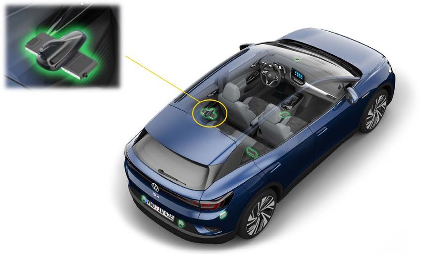
Voice Control
Many operations in the ID.4 can be controlled using voice control. The system can be easily activated by saying “Hello ID...” (the wake-up phrase) or by pressing
the Voice button on the steering wheel.
The ID.4 will respond by saying by saying phrases such as “Yes?” or “What would you like to do?” and reacts intuitively to voice commands such as “I feel cold”
when the 2-zone Climatronic is installed. New digital microphones drastically improve voice recognition and quality when making phone calls and pinpoint
who is speaking (driver or front passenger).
"I feel cold"
"Hello, ID..."
26Climate Control
Operating Unit for Lighting EX59
The front window defrost and heated rear window function have both been moved into the light and visibility cluster. This cluster provides all light and
visibility functions into one easy-to-reach control.
Windscreen defrost Heated rear window
function on/off on/off
27Climate Control
ID.4 Component Locations
Heater and Air Conditioning Control Module J979 Vehicle Interior Temperature Sensor G1090
The heater and air conditioning control module is located to the right of the air The vehicle interior temperature sensor is located between the center
conditioning unit under the dash panel. vent and the storage compartment in the center console.
Heater and Air Conditioning
System Control Unit J979
Vehicle Interior Temperature
Sensor G1090
28Climate Control
Heater and Air Conditioning Unit R1234yf/R744
2-part Basic Concept
The MEB has a completely new heater and air conditioning unit. The unit is two
pieces. There is an intake box in front of the bulkhead (under the hood) and a
distribution box in the cabin.
Interior heating uses a PTC heating element. Vehicles utilizing R744 refrigerant
(Canada) may be equipped with a heat pump heat exchanger system.
Underhood Intake Box
Intake Box Recirculated Air Duct
Under the Hood
Distribution Box in Cabin
29Climate Control
Heater and Air Conditioning Unit R1234yf/R744
Interior Filter
The dust and pollen filter is accessed through the engine compartment and can
be removed by unclipping the cover.
The air intake box is designed to accommodate two filters. The North American
Region uses a single filter element.
Cover
Interior Filter
30Electrical System
Networking in the ID.4
There are new and extensive high-speed communication channels in the ID.4. These range in speed between 500 kbit/s and 1 Gbit/s. These modules utilize
some existing, and some new bus systems.
EV Battery Multifunction Running Powertrain Convenience
CAN-Bus CAN-Bus Steering Wheel Gear CAN-Bus CAN-Bus
CAN-Bus CAN-Bus
2,000 kbit/s 500 kbit/s 500 kbit/s 2,000 kbit/s 2,000 kbit/s 500 kbit/s
Driver
Connectivity MIB Display
Assistance Ethernet Ethernet
CAN-Bus CAN-Bus CAN-Bus
CAN-Bus
2,000 kbit/s 100 Mbit/s 1 Gbit/s 500 kbit/s 500 kbit/s 2,000 kbit/s
31Electrical System
Networking in the ID.4
Two new control modules, the J533 (ICAS1) and J794 (ICAS3) are the primary processors. ICAS (In-Car Application Server) modules are central computers/servers
that bring together a variety of basic services and vehicle functions to control the vehicle systems.
J533 (ICAS1) 8123 AB CAN J794 (ICAS3)
8124 Ethernet Switch Ethernet Bridge Ethernet, 100 Mbit/s
C002 Ethernet 1 Gbit/s
CON. 5F 8125
MIB CAN-Bus 500 kbit/s
C003 CAN MIB CAN
CAN-FD AB 2,000 kbit/s
Driver Assist CAN
J965 Convenience CAN-Bus 500 kbit/s
LVDS
Convenience CAN
J772
LVDS
J1192 J1254
R242 Connectivity CAN-Bus 500 kbit/s
J1193 J685 L385
J428
J949 J1194
J519
J1195
J666
Legend J525
5F Information Electronics Display Control J685 Front Information Display Control Head
8123 Application Server 1 System 1 Adaptive J794 Information Electronics Control Module 1
8124 Application Server 1 System 2 Java J949 Control Module for Emergency Call Module and Communication Unit
8125 Application Server 3, System 1 for Infotainment J965 Access/Start System Interface
C002 Software Cluster, Imbedded 1 J1192 Burglary Protection Control Module 2
C003 Software Cluster, Housekeeping 1 J1193 Burglary Protection Control Module 3
J428 Control Module for Adaptive Cruise Control J1194 Burglary Protection Control Module 4
J519 Vehicle Electrical System Control Module J1195 Burglary Protection Control Module 5
J525 Digital Sound System Control Module J1254 Driver Information System Control Module with Display Unit
J533 Data Bus on Board Diagnostic Interface (ICAS1) L385 Dynamic Lighting Strip 1 for Information in Instrument Panel
J666 Internet Access Control Module R242 Driver Assistance Systems Front Camera
32 More information regarding the ID.4 networking system can be
found in SSP 871213 ID.4 Electrical Systems.Electrical System
Onboard Supply
The 12V battery is needed for the electrical demands of all 12V consumers. In addition, the 12-volt battery is needed to enable high voltage flow. The 12-
volt system controls the high-voltage contactors that connect the high-voltage battery to the high-voltage circuit. A electric vehicle with discharged 12-volt
battery cannot be “started.”
Once the high voltage system is enabled, the Voltage Converter A19 provides the 12-volt vehicle electrical system with power from the high-voltage battery.
Battery Monitor Control Unit J367 Negative Jump Starting Point
Voltage Converter A19 12-volt Battery
SB Fuse Panel
SA Fuse Panel
12-volt Wire
High-voltage Cable SC Fuse Panel
Positive Jump Starting Point 12-volt Main Supply Wire
If a jump box is ever used to “start” and ID.4, do
33 not leave it connected after the vehicle “starts.”Electrical System
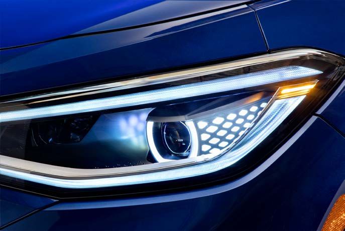
Exterior Lighting - Headlights
Two headlight assemblies are available for the ID.4:
• Basic
• High Headlight
Basic Headlight
High Headlight
More information regarding the ID.4 lighting system can be found
in SSP 871213 ID.4 Electrical Systems.
34Electrical System
Tail Light Clusters
One tail light clusters is available on the ID.4. It uses LED technology.
Tail Light Cluster
Light Configuration
More information regarding the ID.4 lighting system can be found
in SSP 871213 ID.4 Electrical Systems.
35Electrical System
Background Lighting
The ID.4 has background lighting to illuminate different areas of the vehicle
Trim Strip in the Instrument Panel
interior.
The color of the lighting offers either 10 or 30 colors, depending on vehicle
configuration. There are pre-configured lighting profiles and the option of
individually configuring the background lighting in single colors. The single
colors can also be assigned to the individual zones of the vehicle interior.
These areas in the vehicle interior are illuminated in the selected color:
• The control clusters on the doors
• The trim strip in the instrument panel
• The mobile telephone storage compartment
The infotainment system background uses the dash panel color selection.
Control Cluster in the Doors
Mobile Phone
Storage Compartment
36Electrical System
Multifunction Steering Wheel
The steering wheel has controls for both the driver assistance systems and the
media system. The controls for the driver assist systems are located on the
left-hand side of the steering wheel. The controls for the media system are
located on the right-hand side. The most important new features are:
• Touch buttons: the conventional buttons and rocker switches have been
replaced by touch buttons on the multifunction steering wheel for the ID.4
• Sliding and two-step operation: new digital functions like sliding and two-
step operation are supported
• Black panel effect: individual symbols on the touch buttons can be
displayed and hidden
Controls for Driver Assist Controls for Media
Systems Playback
37Electrical System
ID. Light
ID. Light is a light strip that stretches across the entire dash panel. Animated light patterns are displayed using LEDs. It is used as a secondary display for
some vehicle functions.
The ID.Light supports the following functions:
• Welcome and goodbye
• Locking and unlocking ID. Light
• Charging process
• Navigation
• Voice control
• Incoming telephone call
• Braking request from Front Assist
• Activation of absolute reserve mode
(when battery charge is very low)
Absolute reserve mode is activated when the battery charge level is very low to save energy. More
information about this mode can be found in the Owner’s Manual.
38Electrical System
ID. Light
Display Area Assignments
The individual functions use different display areas along the light strip. The animations are shown in the indicated areas.
Driver Centered A
Vehicle Centered B
Across Complete Width C
Note for Driver or Front Passenger D
Welcome & Goodbye A, C
Lock and Unlock C
Charging Process C
Navigation C
Voice Control D
Incoming Telephone Call B
Braking Request C
Absolute reserve Mode C
39Electrical System
Vehicle Activation
Vehicle activation is executed by both the Data Bus on Board Diagnostic Interface J533 (ICAS1) and the Vehicle Electrical System Control Module J519. The J533 is
the primary module. The J519 reads the ignition starter button and activates the terminal 15 relay.
Process Start: Vehicle unlocked /driver seat not occupied The key approaches the vehicle and the vehicle unlocks.
The "Comfort Ready" state allows the driver to operate the
infotainment system and the air conditioning even when the
ignition is off. It is activated when the seat occupied sensor
Comfort Ready: Driver seat occupied, ignition off, air conditioning active, detects a weight. The vehicle key does not have to be inside the
infotainment active vehicle.
The high-voltage circuit is audibly closed upon activation. A
"Welcome driver" message is displayed in the dash panel insert.
The ignition can be activated using either the ignition starter
button on the steering column or by pressing the brake pedal.
The display in the dash panel insert switches to the standard
Ignition switched on PARK view. In addition, all control displays are shown briefly.
The word PARK informs the driver that the parking brake is
activated.
To prepare the vehicle for driving, the driver needs to press the
brake and select a gear. The parking brake disengages and the
word READY appears in the dash panel insert.
Ready to Drive READY
The vehicle slowly starts to roll once the driver releases the
brake pedal.
40Infotainment
Dash Panel Insert
J1254 - Control Unit with Display Unit for Driver
Information System
• Diagonal display of 5.3”
• Display resolution 800 x 400 pixels
• Graphics content provided by ICAS3 (J794)
• Integrated driving mode display using LED’s next to the display Driving Mode Selector
• Now only four warning lights in form of LED’s
• Subscriber on Display and Operation CAN-Bus
The functions of J1254 differ greatly from MQB instrument clusters. For
example, Infotainment content, vehicle status and driving data are not
displayed. Also, the control module is not an immobilizer or component
protection subscriber.
The display is located in a housing with the drive mode selector and
the parking brake button. The component does not have its own
loudspeaker. All information and warning tones are output through the
audio system.
Control Unit with Display Unit for Driver Information System J1254
41Infotainment
Dash Panel Insert
View
The driver can switch between three views with the VIEW touch control on the
multifunction steering wheel:
• Standard
• Navigation
• Driver assist systems Standard View
The vehicle always starts in the standard view. The following information can
be shown in the display area:
• Warning lamps
• Pop-up warning and information messages
• Current speed
• Battery charge level and remaining range
• Available power and currently used power (blue bar)
• Energy recovery availability and current energy recovery intensity (green Navigation View
bar)
• Driver assist systems
• Navigation
VIEW Touch Control
42 Driver assist systems viewInfotainment
Radio Navigation
Discover Pro Navigation System
• Display and control panel with 12” screen (measured diagonal)
• Screen resolution: Up to 1666 x 820 pixels
• Control module J794 behind glove box
• Homescreen 2.0
• Display of navigation map on display and control panel
• Contactless gesture control
• Touch slider (touch-sensitive strip as used in Golf 2020)
• FM and DAB+ radio reception
• Data bus connections:
– Ethernet 1 Gbit/s
– Display and operation CAN bus
Control Module for Information Electronics J794
43Infotainment
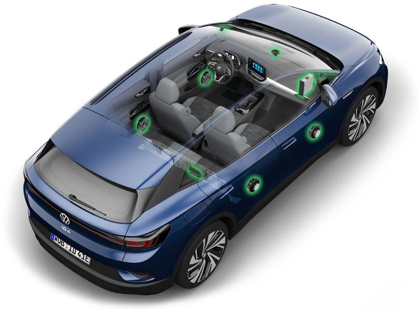
Sound System
Two sound systems are available for the ID.4: J949 OCU
Center Loudspeaker (location prior to
week 10/20) Treble
• Basic sound: 4 + 1 speakers
Speaker
• Premium sound: 6 + 1 speakers
The standard center speaker has two functions: it is used both for
music playback and for emergency call communication. To ensure
it functions in an emergency, it is connected to the Control Module
for Emergency Call Module and Communication Unit J949 (OCU).
The remaining speakers are controlled by the 4-channel amplifier
of the Information Electronics J794 (ICAS3).
The sound system speakers are used for all acoustic warnings in the
vehicle (parking aid and instrument cluster).
J749
ICAS3
Bass Speaker
Speakers Basic Sound Sound Package
Front Treble Broadband
Front Bass J949 OCU Speaker
(location after
Center week 10/20)
Rear Broadband -
44Infotainment
Antenna Systems
Mobile Communications Antennas
The illustration shows the mobile communication aerials. In vehicles with a panoramic sunroof, the Radio Data Transmission Antenna R180 and the Roof
Antenna RX5 are located above the front camera.
Radio Data Transmission Antenna R180
(only vehicles with panoramic sunroof)
Control Module for Emergency Call Module and
Communication Unit J949
(location prior to production week 9/2020)
Telephone Baseplate R126
Roof Antenna RX5
Internet Access Control Module J666
Control Module for Emergency
Call Module and Communication
Unit J949 (location after
production week 10/2020)
LTE Antenna 1 R297
Transceiving Stabilization Control Module R308
LTE Antenna 2 R306
45Infotainment
Antenna Systems
Radio Antennas
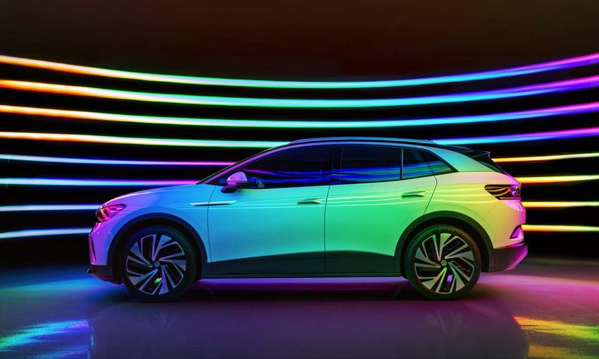
This illustration shows the antenna components. The ID.4 has a composite rear lid, so there is a central Ground connection.
Network Connection
Left Impedance Converter
Ground Connection
Frequency Modulation (FM)
Frequency Filter in Positive Wire Right Impedance Converter
R179
Frequency Modulation (FM)
Frequency Filter in Negative Wire
R178
Heated Wires in Rear Window
46Volkswagen Group of America 2200 Ferdinand Porsche Drive Herndon, VA 20171 March 2021
You can also read