USER MANUAL - FIRST STEPS
←
→
Page content transcription
If your browser does not render page correctly, please read the page content below
USER MANUAL
- FIRST STEPS -
www.cegasa.com
Revision control

                 REV.      DATE                      REASON / RESPONSIBLE

                 00        01/08/2018                First issue
                 01        09/10/2018                R&D
                 02        31/10/2018                R&D
                 03        29/11/2018                R&D
                 04        30/11/2018                R&D
                 05        25/01/2019                Changed CAN connector pin-out
                 06        11/02/2019                Revision IV
                 07        13/02/2019                Revision IV

                  Limitation of Warranty and Liability
             The limitation of warranties and liabilities shall be described in the contractual
             agreements between CEGASA ENERGIA and the buyer.

             The information included in this manual has been written for the purpose of providing the
             user with more detail and clarity in terms of content. Nonetheless, CEGASA ENERGIA
             reserves the right to modify the contents of this manual through future revisions at any
             time and without prior notice.

                  Confidentiality
             All information provided by CEGASA ENERGIA by virtue of this User Manual and any
             data or features that may be disclosed by such shall be completely confidential and may
             not be shared with third parties or used for purposes other than that for which is was
             intended without prior and express written authorization from CEGASA ENERGIA.

                  Limitations on the use of this equipment
             This equipment may not be used in applications for recharging electric vehicles.
             CEGASA ENERGIA shall not be held liable for use with these types of application. The
             buyer shall be wholly responsible.

                  Contact
                      CeGASA ENERGIA
                      C/Marie Curie, 1
                      Parque tecnológico de Álava,
                      01510 Miñano (Vitoria-Gasteiz)-España

                      Tel. +34 945313738
                      www.cegasa.es
             www.cegasa.com

www.cegasa.com                                                                 Page -1- User Manual R10 – First steps –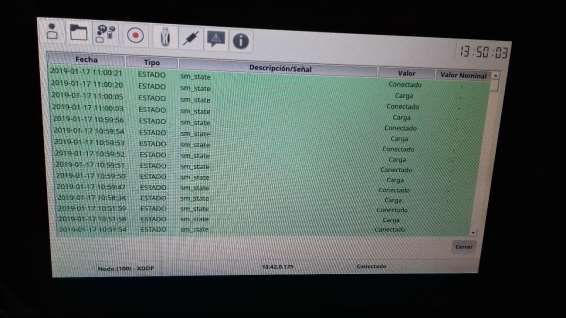
Contents
             1     Introduction .......................................................................................................................... 4
                 1.1      Purpose ......................................................................................................................... 4
                 1.2      Acronyms....................................................................................................................... 4
             2     Technical characteristics of eBick system ............................................................................. 5
             3     Safety..................................................................................................................................... 6
                 3.1      Symbols ......................................................................................................................... 6
                 3.2      General information ...................................................................................................... 7
                 3.3      Safety instructions – Potential hazards ......................................................................... 7
                 3.5      Electrical safety ............................................................................................................. 8
                 3.6      Mechanical safety ......................................................................................................... 8
                 3.7      User requirements ........................................................................................................ 8
                 3.8      Lockout-tagout of machines and installations (LOTO) .................................................. 9
                 3.9      Switching, measurements and checks .......................................................................... 9
             4     Assembly of the equipment ................................................................................................ 10
                 4.1      Potential hazards......................................................................................................... 11
                 4.2      Initial check ................................................................................................................. 11
                 4.3      Fitting the modules ..................................................................................................... 12
             5     Commissioning the equipment ........................................................................................... 18
                 5.1      System start-up and shut-down processes ................................................................. 18
                 5.2      Power connection process .......................................................................................... 18
                 5.3      Pre-charge process (only in stand-alone mode) ......................................................... 19
                 5.4      ID Configuration (Only if necessary)............................................................................ 19
                 5.5      Current calibration (Only if necessary) ....................................................................... 25
             6     Data display ......................................................................................................................... 27
                 6.1      Change of language ..................................................................................................... 27
                 6.2      HMI display.................................................................................................................. 27
                 6.3      Change system date and time ..................................................................................... 31
             7     Communications ................................................................................................................. 35
                 7.1      Introduction ................................................................................................................ 35
                 7.2      CAN protocol ............................................................................................................... 35
                 7.3      Modbus protocol ......................................................................................................... 35
                 7.4      CAN object dictionary & Modbus map........................................................................ 35
              7.5   Configuration with VICTRON ENERGY equipment ...................................................... 35
             www.cegasa.com

www.cegasa.com                                                                                                            Page -2- User Manual R10 – First steps –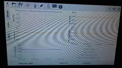
8     Working with the eBick ....................................................................................................... 36
                 8.1      Precharge .................................................................................................................... 36
                 8.2      Charging ...................................................................................................................... 36
                   8.2.1          MCP Series........................................................................................................... 36
                   8.2.2          MCP Parallels ....................................................................................................... 37
                 8.3      Discharging .................................................................................................................. 37
                 8.4      Equalizing .................................................................................................................... 37
                 8.5      SOC Algorithm ............................................................................................................. 38
                 8.6      Alarm reset .................................................................................................................. 38
                 8.7      Ultra-consumption mode ............................................................................................ 39
             9     Environmental operating conditions................................................................................... 39
             10        Maintenance and storage procedure.............................................................................. 39
             11        Transport rules ................................................................................................................ 40
             12        Product warranty ............................................................................................................ 40

             www.cegasa.com

www.cegasa.com                                                                                                         Page -3- User Manual R10 – First steps –
1 Introduction

             1.1 Purpose

             The following document presents the first steps to ensure that the eBicks are installed
             and used safely. The company recommends reading the whole user manual beforehand,
             which can be downloaded from the website or requested in electronic format from the
             company supplying the equipment

             1.2 Acronyms

                 FAT               Factory Acceptance Tests

                 BMS               Battery management system

                 eBick             Battery pack 48V

                 GBMS              Global battery management system

                 MCP               Control and protections module

                 SOC               State of charge.

                 SOF               State of function. Maximum amount of current
                                   permissible loading or unloading at any time

             www.cegasa.com

www.cegasa.com                                                                Page -4- User Manual R10 – First steps –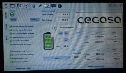
2 Technical characteristics of eBick system

        Module MCP (Control and protections)        MCP SERIEs                MCP PARALLELs

        Chemistry                                   LiFePO4 (LFP)              LiFePO4 (LFP)

        Rated voltage [V]                      Depending on the number                 48
                                                of modules connected in
        Voltage range [V]                                series                     41 - 52,5
                                                   (consult CEGASA)
                                                                          Depending on the
                                                          180
        Capacity [Ah]                                                     number of modules
                                                                          connected

        Energy [KWh]                            Depending on the number of modules connected

        I MAX charge continuous [A]                      180                         250
        I MAX discharge continuous [A]                   180                         250
        I MAX discharge pulse (seg.) [A]             360 (15seg)                 360 (30seg)
        Rated power continuous [KW]            Depending on the number             12KW
                                                of modules connected in
        Rated power pulse [KW]                          series                       17KW

                                                                > 6000 (70% DoD)
        Number of cycles                                        > 5000 (80% DoD)
                                                                > 4000 (90% DoD)
        Temperature range in (ºC) Charge                         From 0 to +50ºC
        Temperature range in (ºC) Discharge                     From -20 to +60ºC
        Storage temperature (ºC)                                From -20 to +45ºC
        Storage temperature recommended (ºC)                    From 15 to +25ºC

                                                Anderson SB175 (Wire    Anderson SB350 (Wire
        Power connector
                                                   section 50mm2)           section 70mm2)
                                                Depending on the number of modules connected
        Dimensions (L x P x A, mm)
                                                Depending on the number of modules connected
        Weight (Kg)
        Degree of envelope protection                                 IP 30
                                               Table 1.

             www.cegasa.com

www.cegasa.com                                                            Page -5- User Manual R10 – First steps –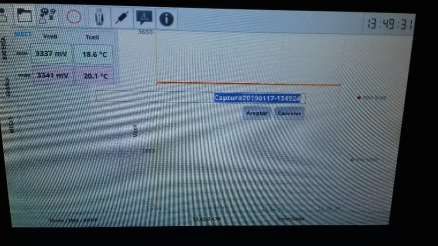
3 Safety

             3.1 Symbols

                      Caution, electrical risk

                     Installation or manipulation near flammable materials is forbidden

                      Read the user manual before proceeding to the installation

                      Caution, high weight that can cause damage in a correct manipulation
                      of the equipment is done

                      Caution, corrosive substances

                      Use protection glasses

                      Do not dispose as domestic waste

                      Recyclable product

                      Disconnect the equipment before maintenance work

                       Caution in the manipulation of equipment sensible to electrostatic
                       electricity

             www.cegasa.com

www.cegasa.com                                                          Page -6- User Manual R10 – First steps –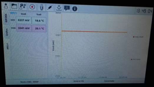
3.2 General information

             The eBick is a smart energy storage system with Li-ion cells.

             The whole system contains a high energy capacity. To minimize the risk of electric shock,
             short-circuit, explosion and/or fire, follow the relevant procedures and local guidelines,
             as well as the instructions that are included with the system.

             Only qualified personnel should perform the installation, in accordance with the
             applicable regulations. Systems with visible electrical connections have to be isolated
             from public access. For safety reasons, cover all direct connections and terminals.

             Carefully read, understand and apply all requirements presented in this section.

             3.3 Safety instructions – Potential hazards

                      •   The area around the eBick shall be kept clear and free of combustible
                          materials, gasoline and/or other flammable fumes, vapours and liquids.

                      •   The area defined by safety margins for the necessary supply and venting
                          of air shall be respected.

                      •   In the event of an emergency the eBick has electrical safety cut-off
                          elements (fuses and contactors). It is advisable to install an element that
                          protects against overcurrent and possible short-circuiting. It is also
                          advisable that the cut-off element can be manually operated if necessary.
                          Remember, because this is a battery the STRING’s internal DC bus will
                          always have a voltage.

                      •   Do not use the module if any of its parts have been immersed in water.
                          A water damaged cell is potentially dangerous. Any attempts to use the
                          system could cause a fire or an explosion. In such cases, contact CEGASA
                          ENERGIA to have the battery pack inspected.

                      •   The following instructions shall always be followed:

                              o   Any air inlet or outlet within the room shall be kept clear and
                                  free of obstacles.

                              o   The floor shall be capable of bearing the weight of the STRING.

                              o   There shall be no obvious signs of wear on any STRING
                                  element.

                              o   As this is a battery, there is voltage on the +/- terminals
                                  whenever the MCP contactor is closed.

             www.cegasa.com

www.cegasa.com                                                                   Page -7- User Manual R10 – First steps –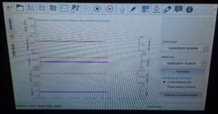
3.5 Electrical safety
                      •   Never remove safety guards or devices that protect against live parts.
                      •   Do not reach inside the STRING or the modules, nor touch any internal
                          component.
                      •   Do not use or handle any eBick component when accidentally wet, or with
                          wet hands or feet.
                      •   In the event of a failure or incident, as a first step cut off the current. To help
                          a person being electrocuted, do not touch them but immediately cut the
                          current. If it is not possible or takes too long to cut the current, try to
                          disengage them by means of an insulating element (wooden strip or board,
                          rope, wooden chair ...).
                      •   Whenever a module is not installed on the STRING, make sure that the
                          power terminals at the front are protected against accidental contact.
                      •   Make sure that the output and input connection cables are not short-
                          circuited.
                      •   Make sure there is no short circuit between positive and negative terminals
                          at any point.
                      •   Make sure there is always protective insulation on the output and input
                          cables and a reliable connection.
                      •   Never use cables that are visibly damaged or that may be suspected of
                          being damaged.
                      •   Minimise conductivity, avoiding surfaces in contact with water. Hands and
                          clothes have to be dry.
                      •   Do not use, install or store the system under wet or damp conditions.

             3.6 Mechanical safety
                      •   Due to the weight of the battery modules (> 100 kg), mechanical means
                          have to be employed to install them.
                      •   Do not stack eBick modules more than 4 high.

             3.7 User requirements
             In addition to personnel who work with the module, workplace users should also
             implement safety measure by applying the minimum provisions of RD 614/2001 on the
             protection of the health and safety of workers exposed to electrical risk in the workplace.
             Hazards related to electrical risk are specifically identified during the work process with
             this equipment. This does not exclude the possible existence of other risks present
             during handling and use, such as overexertion, posture, or other measures against
             health risks. Operators shall receive the necessary training, sufficient to be able to
             prevent and avoid any risks arising from use of the equipment.
             By design the equipment protects against these risks under normal operating conditions,
             however, it is with operations that differ from normal ones (installation, maintenance, ...)
             where special precautions have to be taken.

             Particular care should be taken when handling modules, due to their weight. Respect
             guidelines according to current regulations regarding ergonomics in the workplace
             (Royal Decree 487/1997). Use appropriate handling equipment.

             www.cegasa.com

www.cegasa.com                                                                      Page -8- User Manual R10 – First steps –
3.8 Lockout-tagout of machines and installations (LOTO)
To perform operations absent of voltage (LOTO), the device must be locked and tagged
to non-hazardous voltage values. The following section is based on the lockout-tagout
at several points according to RD 614/2001:
1. Restrict access to the work area to prevent entry of unauthorised personnel.
2. It shall be disconnected and isolated from the supply network or the connection
to the converter.
3. Once disconnected, the STRING shall be sectioned into parts with voltages
below 75 VDC.
4. The terminals of these parts shall be protected by insulating caps designed for
this purpose.
5. Given that the batteries are an energy storage system, it is impossible to make
certain points of the system free of voltage. If there is any exposed point where
the voltage cannot be eliminated, the terminals will have to be tagged, indicating
the voltage value at that point.
6. Prior to conducting any work, the voltage shall be measured at the point where
the work is to be done. Some points may be energised directly from the batteries.
To carry this out, it is necessary to do the following:
• Use only 1000V insulated tools
• If terminals are exposed during the sectioning process, use 1000V rated
insulating gloves.
• Use a face shield during the work.
• Should it be necessary to perform an operation on a battery pack, place the
modules on Insulating matting.
• Use insulating footwear.
• To avoid possible short-circuiting, do not carry any conductive device (e.g.
pens, tape measures, etc.) during the work.
• Do not wear any metal, conductive or sharp-edged accessories.
3.9 Switching, measurements and checks
The regulation permits operations and interventions without lockout-tagout, provided that
an equivalent level of safety is guaranteed.
These interventions are called switching, trials and checks. They have to be carried out
by authorised personnel with protection devices and personal protective equipment
appropriate for the voltages in question.
It should be especially protected against short-circuits. Instructions to follow:
• The operations shall only be carried by authorised, duly trained, personnel.
www.cegasa.com
www.cegasa.com Page -9- User Manual R10 – First steps –• Safety apparel that covers the whole body (long sleeves) shall be used.
Fireproof or flame retardant, with protection against chemicals and arc
flash.
• The work shall be done from a solid, stable support
• If a work table is used, it shall be insulated or covered with Insulating
matting.
• No terminal with an electrical charge should be left uncovered. If, after
removing the connections, the terminals are exposed then they have to be
protected with the terminal covers supplied.
• All tools shall be insulated and rated up to 1000V
• Insulating gloves, at least class 0 (1000V), shall be worn until existing
voltages are cut to levels below 50V DC.
• Operators shall not wear or carry any metal elements or devices.
• The work area shall be free of obstacles.
• If necessary, when there are exposed terminals nylon slings shall be used
instead of chains.
• The operator shall wear a face shield or safety glasses to protect against
short-circuits
• Occasionally, depending on the operation, there should be an OHS
assistant present.
• This person should satisfy that stated in Annex IV of RD 614/2001
4 Assembly of the equipment
Caution: Given that the modules are supplied with electrical charge levels necessary to
maintain the chemical properties of the batteries, the entire installation process shall
perform with the recommended protection equipment.
Each battery module and MCP are pre-wired, pre-set and factory tested. After receiving
and unpacking the system, the installer should find that each string contains:
- An MCP module
- Various eBick modules, these will be P or S depending on the system set-up.
- A BUS termination resistor
- S-BRIDGE CONNECTOR - Only for eBick-S set-ups connected in series
- PROTECTIVE COVER - Only for eBick-P set-ups connected in parallel
- One or more base frames with feet and wall or floor mounting plate/s
- A set of fastening plates for between modules, base frame and MCP (with
fasteners)
- A set of KIT communications and power extenders (*)
(*) Should the project have more than 4 modules, these have to be distributed in several
columns. The wiring between columns will be done using these extension cables.
www.cegasa.com
www.cegasa.com Page -10- User Manual R10 – First steps –4.1 Potential hazards
4.2 Initial check
Before beginning the installation, it is advisable to check the state of the modules:
1. Check the state of the modules No knocks or apparent damage; The nameplate
bearing the serial number fitted to the back of it.
2. With the aid of a multimeter measure DC voltage between the positive and
negative terminals on each battery module (points 1 & 2). Check that polarity is
correct and that the voltage is within range (≈ 48VDC)
The retractable red lug on the cable indicates positive polarity, while its absence
indicates negative polarity. On eBick-S type modules, 2 of the pins have no
voltage. The diagram below shows the correct measurement points.
www.cegasa.com
www.cegasa.com Page -11- User Manual R10 – First steps –3. Check the state of the MCP. No knocks or apparent damage.
4.3 Fitting the modules
1. First place the base frame on the floor and use the feet to level it. If required,
secure the string to the floor, the base frame has a space where brackets can be
fitted. The eBick system is designed to be stationary, with no possibility of
movement and with its weight distributed evenly.
2. Stand the first eBick module on the base frame that is already level and fixed to
the floor. Any module can be inserted in any order in the string, without affecting
power or communications.
3. Stack the rest of eBick modules up to a maximum of 4 high.
www.cegasa.com
www.cegasa.com Page -12- User Manual R10 – First steps –4. Place the MCP on top of the last module and check that the ON/OFF switch at
the back is in the OFF position.
5. Use the fastening plates to fasten all the eBick modules to each other, to the base
frame and to the front of the MCP. Note: Screw length is different when fastening
the MCP (see picture below)
www.cegasa.com
www.cegasa.com Page -13- User Manual R10 – First steps –2 x metal screw M6x20
✓ MCP eBick UNION
2 x metal screw M6x10
✓ BASE FRAME - eBick
UNION
✓ eBick - eBick UNION
6. Assemble the “N” columns that go to form the installation project in the same way
as indicated in the previous steps but without the MCP, which is already fitted on
the first column.
7. Communication connection between modules; starting with the MCP, make the
communication connections between modules using the Male-Female
communication connectors on the left.
If there are several columns in the project, use the Communications Cable
Extender Kit to make the communication connections.
Communications EXTENDER KIT
www.cegasa.com
www.cegasa.com Page -14- User Manual R10 – First steps –On the last eBick module, fit the bus termination resistor on the connector that is
free.
BUS termination resistor
8. Power connection between modules; First check to see if the installation is in
series or parallel and make sure to use PPE (protective gloves and safety
glasses)
8.1 Parallel connection (voltage 48V) - For eBick P cases (Anderson 350)
✓ Without connecting to the MCP (leave this until last) start connecting all the
power connectors between columns; If there are several columns, use the
PARALLEL POWER CABLE EXTENDER KIT at the rear.
POWER EXTENDER KIT
PARALLEL
Anderson connector
SB350
✓ Use the supplied protective cap to protect the power connector left
uncovered on the last eBick module.
www.cegasa.com
www.cegasa.com Page -15- User Manual R10 – First steps –✓ Check polarity and voltage (close to 48Vdc) on the power connector below
the MCP
✓ Use the multimeter to check that there is no continuity between positive and
negative on the MCP power connector (no beep)
✓ If everything is OK, proceed to connect the MCP connector to the already
connected DC BUS connector.
8.2 Series connection (voltage 48V) - For eBick S cases (Anderson SB175)
✓ Without connecting to the MCP (leave this until last) start connecting all the
power connectors between columns; If there are several columns, use the
SERIES POWER CABLE EXTENDER KIT at the rear.
POWER EXTENDER KIT
SERIES
Anderson connector
SB175
✓ Connect the S BRIDGE CONNECTOR to the connector on the last free
module in order to close the VDC BUS
www.cegasa.com
www.cegasa.com Page -16- User Manual R10 – First steps –✓ Check polarity and voltage (close to “Nº modules connected x 48Vdc”) on
the power connector below the MCP.
✓ Use the multimeter to check that there is no continuity between positive and
negative on the MCP power connector (no beep)
✓ If everything is OK, proceed to connect the MCP connector to the already
connected DC BUS connector.
9. At the back of the MCP, connect the earth connection (M-6 bolt) to the earth for
the installation. An earth cable of between 1mm2 - 2.5 mm2 section should be
used (See point 7 in image below)
10. Check at the back of the MCP that there is no voltage or continuity between the
poles on the positive and negative power output connectors. (See points 4 and 6
in image below)
11. At the back of the MCP connect the terminals (M-8) that corresponds to the
installation’s positive and negative terminals. The recommended tightening
torque is 10Nm using a torque wrench. (See points 4 and 6 in image below)
12. At the back of the MCP connect the correct RJ45 communication connectors for
the inverter (MODBUS or CAN BUS). It is recommended that the cable length is
no longer than 20 metres.
www.cegasa.com
www.cegasa.com Page -17- User Manual R10 – First steps –Important notes:
✓ The system is self-powered and does not require connection to an external
supply.
✓ The length of the interconnecting cables affects the final voltage detected by the
application. It is advisable to install the battery as close as possible to the element
that is going to use it (inverter, DC bus, ...) and avoid sharp curves or bends in
the cables. For recommended cable lengths, wire sizes and characteristics,
please contact CEGASA.
5 Commissioning the equipment
5.1 System start-up and shut-down processes
All points included in the previous section should have been followed prior to starting the
system. Once this has been done, the system can be started by pressing the switch on
the MCP from the OFF to ON position.
Pressing the switch powers up the control electronics in the MCP. The GBMS then
checks hardware integrity (own hardware and that of the BMS distributed by
communications) and that the cabinet distribution set-up corresponds with that read (see
point 4.3). If no error is detected, the GBMS allows work with batteries to commence.
The time required for start-up is less than 1 minute.
To stop the system, the same switch should be changed from the ON to OFF position.
The string should never be switched off while current is flowing through the system. The
contactor has to be opened prior to switching off the MCP.
HAZARD: ELECTRONICS SELF-CONSUMPTION
The electronics inside the cabinet are powered by the batteries. If the
batteries are not going to be used for a prolonged period (3-4 weeks), the MCP
has to be turned off manually by pressing the ON/OFF button to OFF.
5.2 Power connection process
eBick systems can operate in 2 different ways: Slave Mode and Stand-alone Mode, it is
advisable ask the supply company in which mode the MCP is configured before the
system is started.
www.cegasa.com
www.cegasa.com Page -18- User Manual R10 – First steps –In slave mode the eBick system depends on a higher-level system, be it SCADA, an
inverter or operation personnel. In this mode, after the system is started it remains in the
ready/disconnected state until it receives an external close contactor command. Until this
order to close the connector is received, the voltage at points 6 and 4 in the image below
is 0V.
In stand-alone mode (48V VICTRON or SMA type commercial converters) eBick
automates several operations, including direct connection by closing the output contactor
if the battery’s safety conditions are met.
In this mode, after starting the eBick system by pressing the ON switch, if no critical error
occurs then the output contactor closes autonomously and automatically, with points 4
and 6 in the image above having 48Vdc from the battery. Consequently, all components
hooked up to the eBick system output bus are fed this nominal voltage.
Likewise, it manages the resets in the event of battery alarms.
5.3 Pre-charge process (only in stand-alone mode)
The pre-charge process is only used in stand-alone mode, designed to be used with
commercial 48V inverters. It requires specific custom-built hardware for this application.
If the bus voltage differs from 48V or if it is certain that the application requires precharge,
please contact CEGASA.
5.4 ID Configuration (Only if necessary)
During the initial start-up, the battery has to be configured for correct communications.
In this example, let’s imagine that we have installed a 4-unit system and are going to
follow the following numbered steps:
www.cegasa.com
www.cegasa.com Page -19- User Manual R10 – First steps –a) We note the serial numbers for each of the battery modules. The serial number is
found on a label at the back of them.
b) Once the MCP is started, it displays all read values as “?” until distribution is
configured.
www.cegasa.com
www.cegasa.com Page -20- User Manual R10 – First steps –Otherwise, this may be because:
a. These are not the configured modules (continue reading)
b. There is a communication fault→Check that the cable is plugged in
correctly.
c. Start-up fault →Restart and recheck
c) Change language and Logging as administrator - Access the "Login" button as
administrator (Select the desired language from the drop-down that appears on the
screen).
The default user is admin and the default password cegasa. Select the desired
language in drop-down. Please contact CEGASA if the access data has been
changed.
d) Access the pencil-shaped “Edit” button
In the dialogue box enter the number of modules in series and parallel. In this
example there are 4 modules to connect in series (final bus voltage of 200Vdc) and
only one string to connect on the system (1 parallel).
Once the number of modules has been configured, the IDs have to be configured
on the “Edit MECs” screen.
The following screen displays what is seen during the first start-up.
www.cegasa.com
www.cegasa.com Page -21- User Manual R10 – First steps –The battery layout table on the right shows the series and parallel configuration
that has been defined in the previous screen.
The software does not show any of the modules during the first start-up. They have
to be configured manually.
To do this, click on the “Add New MEC” button as many times as there are battery
modules. In this particular example, 4 times.
After clicking the button, the software generates battery modules that can then be
configured, and these appear inside the “Available MECs Pool” table. As they have
not yet been configured, they appear with the default values.
In order to identify the modules, it is best to assign the IDs so that they match the
physical layout. (Module number 1 closest to the eBick)
www.cegasa.com
www.cegasa.com Page -22- User Manual R10 – First steps –To change the serial and/or ID number, just click on the one that needs changing
and an on-screen keyboard will appear so that the new number can be entered.
Once the serial numbers have been changed to reflect the ones that had been
written down, select the first one and click on the “The screen now shows a layout that matches its physical counterpart.
e) Restart the system (ON/OFF button) to apply the changes.
After accepting the changes on both pop-up screens, a warning appears,
stating that changes have occurred and requesting permission to restart.
After restarting, the display shows the battery values. The installation is now
completed.
www.cegasa.com
www.cegasa.com Page -24- User Manual R10 – First steps –5.5 Current calibration (Only if necessary)
Note: In order to calibrate, the user has to have accessed the system as an administrator.
All eBick measurement systems are pre-calibrated at the factory. ONLY IF NECESSARY
should calibration of the current transformer be checked in order to minimize possible
reading errors.
The following tools are required to perform this calibration:
- A measurement method that can read the current flowing through the battery,
such as a current clamp or the inverter itself.
- Access to the equipment to charge/discharge the battery, and control over them
in order to vary the current flowing to the battery.
Calibration of the current transformer is done via the touch screen. This configuration is
divided into 2 main parts:
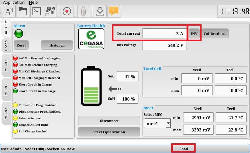
1. Polarity correction
On the main screen:
Charge or discharge the battery, checking the current being read and battery status.
If current is flowing to the battery (battery charging), current value will be positive and
battery status will be “load”.
If current is being drawn from the battery (battery discharging), current value will be
negative and battery status will be “unload”.
If during this test battery status is the opposite of its real status, the reported direction
of the current can be inverted by pressing the “INV” button
www.cegasa.com
www.cegasa.com Page -25- User Manual R10 – First steps –2. Current measurement correction
Inside the “Calibration” sub-menu:
If there is a difference between the current being read by the HMI and the current
circulating through the system, the reading can be corrected with adjustments from this
menu.
Note: It is best to perform the calibration when the battery SoC is between 40% and 60%.
Performing the calibration within this range allows the user to change between charge
and discharge status, and to take several points at each of these, making it possible to
perform the calibration in just one operation, without ever reaching 0% or 100% SoC,
which would otherwise trip an MCP safety.
Once on this screen, clicking the reset button clears any stored calibration point, leaving
a blank sheet to begin the calibration.
Calibration begins by charging or discharging the battery to the maximum current value
indicated on the data sheet provided by CEGASA, or the maximum current the inverter
can supply on the installation, whichever is less.
Once the current is read and displayed in the “Measured” box, the actual current can be
written in the “New current point box” and then “Add” can be clicked.
The current value in the inverter can then be changed to a new point and the previous
step repeated.
Calibration is performed by starting at the maximum charge current, passing through
several intermediate points, 0 current value, several intermediate discharge points and
maximum discharge current.
When calibration has finished, press “Finish” to store the new calibration points.
Note: Calibration is done using the point-slope method, interpolating the calibration
points between 2 manually inserted points. Consequently, it is not necessary to calibrate
the current transformer at all working points because the software calculates the
intermediate points.
www.cegasa.com
www.cegasa.com Page -26- User Manual R10 – First steps –6 Data display
6.1 Change of language
a) Access the "Login" button as administrator (Select the desired language from the
drop-down that appears on the screen).
The default user is admin and the default password cegasa. Select the desired
language in drop-down. Please contact CEGASA if the access data has been
changed.
6.2 HMI display
The MCP has a built-in touch screen. This is used to display existing GBMS data. The
HMI includes the following screens:
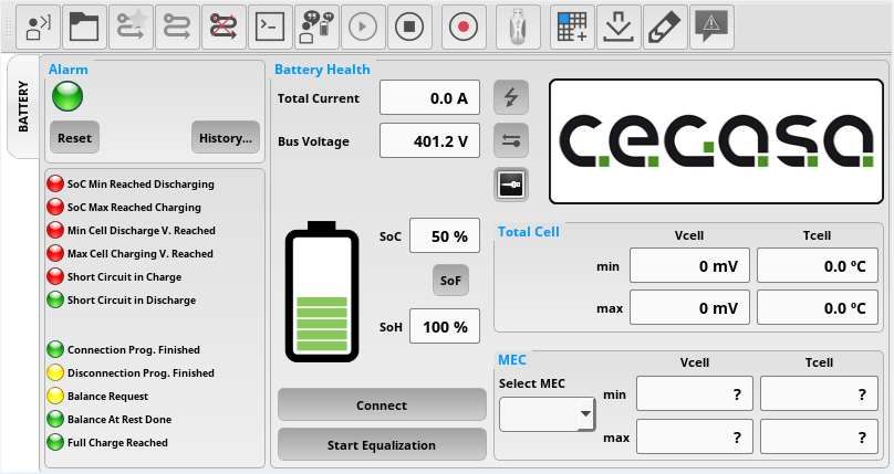
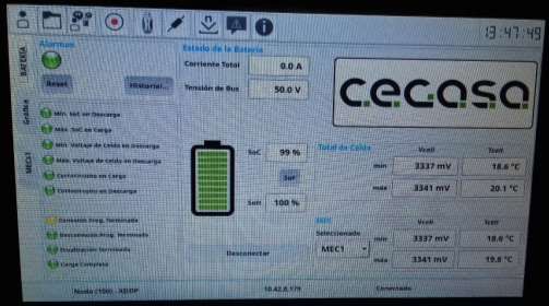
a) Main screen (“BATTERY” tab)
Figure 1. Main screen.
This is the screen displayed when the system is started.
It provides a summary of the most significant battery data:
- State of Charge SoC
- State of Health SoH
- Current value in the system
- Total voltage value
- Minimum and maximum voltage and temperature values in system and per
module
- Battery status (charging, discharging, balancing, on standby...)
- Alarms and flags
www.cegasa.com
www.cegasa.com Page -27- User Manual R10 – First steps –- Connect and disconnect contactor commands can be performed by using the
button (only in administrator mode)
- Alarms can be reset manually (only in administrator mode)
It is also possible to access chart and graph sub-screens from this screen.
b) History screen
Accessed from the “History” tab
Figure 2. Temperature-voltage-current alarm counter
www.cegasa.com
www.cegasa.com Page -28- User Manual R10 – First steps –Figure 3. Partial/total charge and discharge energy capacity log
Figure 4. Log of latest charge and discharge cycles and dates
Figure 5. Alarms per module counter
c) Graph screen (“GRAPH” tab)
www.cegasa.com
www.cegasa.com Page -29- User Manual R10 – First steps –Figure 6. Graph screen
d) MECs screen (” MECs” tab)
Figure 7. MECs screen
e) Alarms and events screen
www.cegasa.com
www.cegasa.com Page -30- User Manual R10 – First steps –Figure 8. Alarms and events screen
This screen is accessible from any of the previous screens. To open it, click the alarm
icon on the top ribbon menu. On this screen it is possible to view all the events generated
within the string chronologically, for subsequent use or failure analysis.
It shows the type of event that has occurred (alarm, trip, command ...) if it has been
activated/deactivated, the time it occurred, and the value at which this change occurred,
whether a relevant value associated with the event exists.
f) Firmware version info screen
6.3 Change system date and time
a) Access the “Login” button as administrator. The default user is admin and the
default password is cegasa. Please contact your administrator if the access
data has been changed.
www.cegasa.com
www.cegasa.com Page -31- User Manual R10 – First steps –b) Click on the button at the far top right of the screen to access change date/time
c) Click on the time to access the change date/time menu
d) Change the date and time to the current one and press the “Accept” button. A
prompt will appear to confirm the change.
e) Recording process data
On the MCP screen it is possible to record charge/discharge process data to the
MCP’s memory and then display it on the screen or export it as file to a USB memory
stick.
a) Access the “Login” button as administrator. The default user is admin and the
default password is cegasa. Please contact your administrator if the access
data has been changed.
b) Press the “Record” button to start the data recording process; a box appears
when the button is pressed, inside which the name of the test that the customer
wants can be written.
www.cegasa.com
www.cegasa.com Page -32- User Manual R10 – First steps –c) The data recording process is stopped by pressing the “Record” button again.
d) To access the created file, click on the “Folder” button.
e) Select the created file to view the graphs or export the file to a USB memory in
csv or binary format.
www.cegasa.com
www.cegasa.com Page -33- User Manual R10 – First steps –The created file can be deleted by holding the cursor down on the file, prompting
a dialogue box to appear to enable this option.
To export the file in csv or binary format, first insert a USB memory stick into the
USB port at the front of the MCP.
f) After saving the file, click the USB icon on the top ribbon menu and wait for the
system to confirm that the USB can be physically removed.
www.cegasa.com
www.cegasa.com Page -34- User Manual R10 – First steps –7 Communications
7.1 Introduction
The string is capable of external communications for data exchange and system control.
For such purposes it uses CAN and Modbus TCP protocols
7.2 CAN protocol
An RJ-45 connector is available for external communication.
The pinout for the connection cable is shown below. If needed, this pinout can be altered.
Please consult CEGASA
PIN Signal
7 CAN_H
8 CAN_L
3 CAN_GND
7.3 Modbus protocol
An RJ-45 connector is available at the back of the MCP for communication via Modbus.
CAT5 cable is recommended for the connection, with a maximum theoretical length of
100m.
7.4 CAN object dictionary & Modbus map
Please request the Excel file of the CAN object dictionary & Modbus map from CEGASA
7.5 Configuration with VICTRON ENERGY equipment
To configure VICTRON equipment to work with eBick systems, please request the
corresponding documents from CEGASA.
www.cegasa.com
www.cegasa.com Page -35- User Manual R10 – First steps –8 Working with the eBick
8.1 Precharge
There is a differentiation between the devices connected in parallel to 48Vdc (MCP
Parallel) and the equipment connected in series (MCP series) for the connection
process.
MCP Parallel – Parallel devices have a CONNECTED preload system to connect
automatically. That is, the equipment is autonomous in the connection and reconnection
of the system. For the connection it has a number of attempts in case of not being able
to make it, the device will show an error indicating the alarm on the screen.
MCP Series – This equipment has the preload system DISCONNECTED, so it is
necessary that other equipment (inverter or similar) indicates the power connection by
communications when the bus is safely preloaded.
8.2 Charging
The eBick system always works with CAN BUS communications with the inverters. In
this way the MCP always communicates to the inverter the charging voltage and the
maximum charging current that must be respected at all times, depending on variables
such as the state of charge of the battery (SOC) and the temperature of the cells. In this
way, depending on the charging conditions, we optimize the process to preserve the
safety and life of the batteries. This is known as the SOF (State of Function) function.
8.2.1 MCP Series
Charging current by SOF
SOC Charging current
1. 0-94% 180A x Temperature coefficient
2. 95-99% 20A x Temperature coefficient
3. 100% 0A x Temperature coefficient
Temperature
range in Temperature
CHARGE (ºC) coefficient
0-5 0,1
6-11 0,2
11-45 0,5
46-50 0,1
Charging voltage by SOF
Temperature
range in
CHARGE Charging voltage
(ºC) (V)
0-5 51,2 x Nºmodules
6-11 51,5 x Nºmodules
11-45 51,9 x Nºmodules
46-50 51,2 x Nºmodules
www.cegasa.com
www.cegasa.com Page -36- User Manual R10 – First steps –8.2.2 MCP Parallels
Charging current by SOF
SOC Charging current
1. 0-94% 250A x Temperature coefficient
2. 95-99% 20A x Number of modules in parallel x Temperature coefficient
3. 100% 0A x Temperature coefficient
Temperature
range in Temperature
CHARGE (ºC) coefficient
0-5 0,2
6-11 0,5
11-45 1
46-50 0,2
Charging voltage by SOF
Temperature
range in
CHARGE Charging voltage
(ºC) (V)
0-5 51,2
6-11 51,5
11-45 51,9
46-50 51,2
8.3 Discharging
In the discharging process, the maximum current demanded by the application is
guaranteed at all times, provided that the value does not exceed that of the alarms of the
eBick system in continuous and pulse mode (see point 2).
The minimum voltage that cannot be lowered in the discharge is sent to the inverter to
ensure battery operation. This value is:
Vmin = 42V x Number modules connected in series
8.4 Equalizing
Equalization process in the eBick family is passive and is governed by the MCP only.
The system enters in equalization mode when the voltage dispersion within the system
exceeds 40mV. The equipment goes out to equalize when the voltage dispersion
reaches a value of 10mV or when one of the series reaches the limit value of 3340mV.
www.cegasa.com
www.cegasa.com Page -37- User Manual R10 – First steps –8.5 SOC Algorithm
The MCP calculates the SOC of the eBick system at all times by coulombometry,
including the internal consumption of its own electronics. To avoid accumulated errors,
you have several points to update the charge status at different levels:
1. 100% update - Regardless of the SOC shown on the screen if the series voltage
levels (in the CHARGE process at a certain current) reach a certain voltage value
the SOC automatically changes to 100% since the MCP interprets that the
system is really charged at that level.
2. 5% update - Regardless of the SOC shown on the screen if the series voltage
levels (in the DISCHARGE process at a certain current) reach a certain voltage
value the SOC automatically changes to 5% since the MCP interprets that the
system is really discharged at that level.
3. Without current (OCV) – Regardless of the SOC shown on the screen if the
series voltage levels (in the IDDLE process, current 0A) reach a certain voltage
value after a stabilization time the SOC automatically changes to the value
indicated in the algorithm since the MCP interprets that the system really is at
that level. This update is only for SOC values below 30%
8.6 Alarm reset
There is a differentiation between the devices connected in parallel to 48Vdc (MCP
Parallel) and the equipment connected in series (MCP serial) for the alarm reset process.
MCP Parallel – Parallel equipment has a CONNECTED preload system to automatically
connect in case of alarm recovery. That is, the equipment is autonomous in the
reconnection (alarm reset) of the system. For the connection it has a number of attempts
(3) in case of not being able to do it due to a problem, the device will go to error indicating
the alarm on the screen.
Note: There are two alarms that do not have the reset process as it is understood that
they are important from the point of view of system security. They are related to the
voltage difference and temperature difference. If in any case the difference in voltages
or temperatures exceeds a certain value for each case, it is understood that there is a
damaged cell or probe (voltage or temperature) and the process of automatic reset of
alarm is eliminated.
MCP Serie – Serial equipment has the preload system DISCONNECTED, so it is
necessary that the inverter indicates the reconnection of the power by communications
when the bus is safely preloaded and the battery has no alarm on screen.
www.cegasa.com
www.cegasa.com Page -38- User Manual R10 – First steps –8.7 Ultra-consumption mode
In the case that there is any problem in the discharge process or in the disconnection of
the equipment, the MCP has an added security accessing the ultra-consumption mode
to preserve the life and safety of the batteries avoiding overloading them.
In this way, if the MCP detects that one of the series is below the established safety
threshold, it initiates a disconnection protocol (ultra-consumption mode) to ensure the
safe mode of operation of the batteries. In this way the consumption of the screen, the
output contactor (if powered), the BMS and all the electronics of the MCP are canceled.
The only way out of this state is to turn the MCP of the power button off and on again.
Contact CEGASA if the equipment has entered in this mode to ensure system re-
establishment.
9 Environmental operating conditions
Parameters Technical Observations
specifications
Temperature range in CHARGE (ºC)
0ºC ~ + 50ºC
Temperature range in DISCHARGE (ºC)
-20ºC ~ + 50ºC
Humidity (RH%) 5%≤RH≤85%
10 Maintenance and storage procedure
The customer is responsible for complying with this procedure:
✓ Check monthly the voltage (within the range of the battery) and the visual state
of the envelope (no bumps, swelling or discoloration) and the positive and
negative terminals in MCP (no oxidation), check the tightening of the latter to the
output cable.
✓ Every 12 months it is mandatory to carry out a battery charging process up to 40
- 60% SoC.
Storage recommendations:
✓ Do not expose directly to the sun or to meteorological precipitation
www.cegasa.com
www.cegasa.com Page -39- User Manual R10 – First steps –Parameters Technical Observations
specifications
SOC RECOMMENDED
40-60%
STORAGE TEMPERATURE RANGE (ºC)
-20ºC ~ + 45ºC
STORAGE TEMPERATURE RANGE
RECOMMENDED (ºC)
15ºC ~ + 25ºC
HUMIDITY 5% ≤RH≤85%
11 Transport rules
ADR material: Class 9 Hazardous substancies.
A MANUAL TEST & CRITERIA, Subsection 38.3.
The BP complies with the regulations and tests established in UN MANUAL TEST &
CRITERIA.
12 Product warranty
The warranty of this product is 2 years or a maximum of 2,000 cycles that meet the
conditions described in this document.
www.cegasa.com
www.cegasa.com Page -40- User Manual R10 – First steps –You can also read