Gas cylinder scale model GCS-1 Gasflaschenwaage Typ GCS-1 Balance pour bouteilles de gaz type GCS-1 Bilancia per bombole modello GCS-1 - Gas ...
←
→
Page content transcription
If your browser does not render page correctly, please read the page content below
Operating instructions
                              Betriebsanleitung
                              Mode d'emploi
                              Manuale d‘uso

Gas cylinder scale model GCS-1                         EN

Gasflaschenwaage Typ GCS-1                             DE

Balance pour bouteilles de gaz type GCS-1              FR

Bilancia per bombole modello GCS-1                     IT

            Gas cylinder scale model GCS-1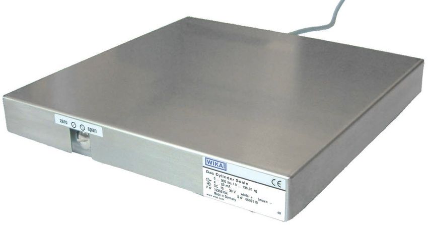
EN Operating instructions model GCS-1                                      Page             3 - 18

DE Betriebsanleitung Typ GCS-1                                             Seite          19 - 34

FR Mode d’emploi type GCS-1                                                Page           35 - 50

IT Manuale d’uso, modello GCS-1                                            Pagina         51 - 66

   © 05/2003 WIKA Alexander Wiegand SE & Co. KG
   All rights reserved. / Alle Rechte vorbehalten.

   WIKA® is a registered trademark in various countries.
   WIKA® ist eine geschützte Marke in verschiedenen Ländern.

   Prior to starting any work, read the operating instructions!
   Keep for later use!
                                                                                                       11145676.09 03/2022 EN/DE/FR/IT

   Vor Beginn aller Arbeiten Betriebsanleitung lesen!
   Zum späteren Gebrauch aufbewahren!

   Lire le mode d‘emploi avant de commencer toute opération !
   A conserver pour une utilisation ultérieure !

   Prima di iniziare ad utilizzare lo strumento, leggere il manuale d‘uso!
   Conservare per future consultazioni!

    2                                     WIKA operating instructions gas cylinder scale model GCS-1
Contents
Contents
EN
1. General information 4
2. Design and function 5
2.1 Overview . . . . . . . . . . . . . . . . . . . . . . . 5
2.2 Description . . . . . . . . . . . . . . . . . . . . . . . 5
2.3 Scope of delivery . . . . . . . . . . . . . . . . . . . . 5
3. Safety 6
3.1 Explanation of symbols . . . . . . . . . . . . . . . . . . 6
3.2 Intended use . . . . . . . . . . . . . . . . . . . . . . 6
3.3 Improper use . . . . . . . . . . . . . . . . . . . . . . 7
3.4 Personnel qualification . . . . . . . . . . . . . . . . . . . 7
3.5 Additional safety instructions for gas cylinder scale per ATEX . . . . . 7
3.6 Special hazards . . . . . . . . . . . . . . . . . . . . . 8
3.7 Labelling/Safety marks . . . . . . . . . . . . . . . . . . . 9
3.8 Ex marking . . . . . . . . . . . . . . . . . . . . . . . 9
3.9 Special conditions for use (X conditions) . . . . . . . . . . . . 10
4. Transport, packaging and storage 10
4.1 Transport . . . . . . . . . . . . . . . . . . . . . . . 10
4.2 Packaging and storage . . . . . . . . . . . . . . . . . . 10
5. Commissioning 11
6. Setting of zero point/span 13
7. Faults 14
8. Maintenance and cleaning 15
8.1 Maintenance . . . . . . . . . . . . . . . . . . . . . . 15
8.2 Cleaning . . . . . . . . . . . . . . . . . . . . . . . 15
9. Return and disposal 16
9.1 Return . . . . . . . . . . . . . . . . . . . . . . . . 16
9.2 Disposal . . . . . . . . . . . . . . . . . . . . . . . 16
10. Specifications 17
10.1 Approvals, directives and certificates . . . . . . . . . . . . . 18
11145676.09 03/2022 EN/DE/FR/IT
10.2 Safety-related maximum values . . . . . . . . . . . . . . . 18
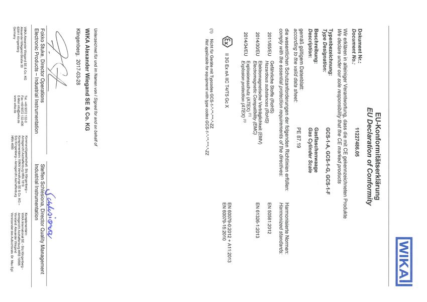
Annex 1: EU declaration of conformity 67
WIKA operating instructions, gas cylinder scale, model GCS-1 3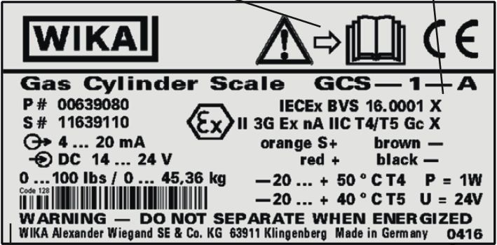
1. General information

     1. General information
     ■ The gas cylinder scale described in the operating instructions has been designed
          and manufactured using state-of-the-art technology. All components are subject
EN        to stringent quality and environmental criteria during production. Our management
          systems are certified to ISO 9001 and ISO 14001.
     ■ These operating instructions contain important information on handling the instru-
          ment. Working safely requires that all safety instructions and work instructions are
          observed.
     ■ Observe the relevant local accident prevention regulations and general safety regula-
          tions for the instrument's range of use.
     ■ The operating instructions are part of the product and must be kept in the immediate
          vicinity of the instrument and readily accessible to skilled personnel at any time. Pass
          the operating instructions on to the next operator or owner of the instrument.
     ■ Skilled personnel must have carefully read and understood the operating instructions
          prior to beginning any work.
     ■ The manufacturer's liability is void in the case of any damage caused by using the
          product contrary to its intended use, non-compliance with these operating instruc-
          tions, assignment of insufficiently qualified skilled personnel or unauthorised modifi-
          cations to the instrument.
     ■ The general terms and conditions contained in the sales documentation shall apply.

     ■ Subject to technical modifications.

     ■ Further information:
          - Internet address:         www.wika.de
          - Relevant data sheet:      PE 87.19
          - Application consultant:   Tel.:   +49 9372/132-0
                                      Fax:    +49 9372/132-406
                                      E-Mail: info@wika.com

     Abbreviations
                                                                                                        11145676.09 03/2022 EN/DE/FR/IT

     2-wire   Two connection lines are used for the voltage supply.
              The measuring signal also provides the supply current.
     U+       Positive power supply terminal
     U-       Negative power supply terminal
     S+       Positive output terminal
     S-       Negative output terminal

      4                                  WIKA operating instructions, gas cylinder scale, model GCS-1
2. Design and function
2. Design and function
2.1 Overview
EN
Potentiometer
Weighing surface
Electrical connection
Product label
2.2 Description
With the gas cylinder scale, the mass of the gas cylinder and its contents is measured
and converted to an electrical signal. This electrical signal varies in proportion to the
mass and can be evaluated accordingly.
2.3 Scope of delivery
■ Gas cylinder scale with 6 m cable outlet
■ Test report
■ Screw, M6
Cross-check scope of delivery with delivery note.
11145676.09 03/2022 EN/DE/FR/IT
WIKA operating instructions, gas cylinder scale, model GCS-1 53. Safety
3. Safety
3.1 Explanation of symbols
EN WARNING!
... indicates a potentially dangerous situation that can result in serious injury
or death, if not avoided.
WARNING!
... indicates a potentially dangerous situation in the hazardous area that
can result in serious injury or death, if not avoided.
CAUTION!
... indicates a potentially dangerous situation that can result in light
injuries or damage to property or the environment, if not avoided.
Information
... points out useful tips, recommendations and information for efficient
and trouble-free operation.
3.2 Intended use
WARNING!
Serious physical injury and/or property damage caused by using
incorrect product version
If an incorrect gas cylinder scale is selected with regard to the measu-
ring range, version and specific measuring conditions, serious physical
injuries and/or damage to property can result.
▶ Before installation, commissioning and operation, ensure that the
appropriate gas cylinder scale has been selected.
The gas cylinder scale is used to measure mass.
The instrument has been designed and built solely for the intended use described here,
and may only be used accordingly.
The technical specifications contained in these operating instructions must be
11145676.09 03/2022 EN/DE/FR/IT
observed. Improper handling or operation of the instrument outside of its technical
specifications requires the instrument to be taken out of service immediately and
inspected by an authorised WIKA service engineer.
The manufacturer shall not be liable for claims of any type based on operation contrary
to the intended use.
6 WIKA operating instructions, gas cylinder scale, model GCS-13. Safety
3.3 Improper use
WARNING!
Injuries through improper use
Improper use of the instrument can lead to hazardous situations and
injuries.
EN
▶ Refrain from unauthorised modifications to the instrument.
Any use beyond or different to the intended use is considered as improper use.
3.4 Personnel qualification
WARNING!
Risk of injury should qualification be insufficient!
Improper handling can result in considerable injury and damage to
property.
▶ The activities described in these operating instructions may only be
carried out by skilled personnel who have the qualifications described
below.
▶ Keep unqualified personnel away from hazardous areas.
Skilled personnel
Skilled personnel are understood to be personnel who, based on their technical training,
knowledge of measurement and control technology and on their experience and
knowledge of country-specific regulations, current standards and directives, are capable
of carrying out the work described and independently recognising potential hazards.
Special knowledge for working with instruments for hazardous areas:
The skilled personnel must have knowledge of ignition protection types, regulations and
provisions for equipment in hazardous areas.
Special operating conditions require further appropriate knowledge, e.g. of aggressive
media.
3.5 Additional safety instructions for gas cylinder scale per ATEX
11145676.09 03/2022 EN/DE/FR/IT
WARNING!
Danger to life due to loss of explosion protection
Non-observance of these instructions and their contents may result in the
loss of explosion protection.
▶ For operation in hazardous areas, observe the lower voltage levels in
accordance with chapter 10.2 “Safety-related maximum values”.
▶ Observe the following instructions:
WIKA operating instructions, gas cylinder scale, model GCS-1 73. Safety
■ Actions or alterations to the gas cylinder scale, which are not described in these
operating instructions, are not permitted.
■ If faults cannot be eliminated, the gas cylinder scale must be taken out of operation
EN immediately and prevented from being accidentally put back into service.
■ Always operate the gas cylinder scale within its overload limits.
■ Observe the operating parameters in accordance with chapter 10 “Specifications”.
■ Ground the cable shield at one end, preferably in the safe non-Ex area
(EN 60079-14). For instruments with cable outlet, the shield is connected to the
case. An additional connection of the shield is only permitted if any potential losses
between the shield connection (e.g. at the supply unit) and the case can be avoided
(see EN 60079-14).
■ Connect the gas cylinder scale with marking “Ex nA IIC T4/T5” to a power and signal
circuit with transient protection in accordance with EN 60079-15, chapter 23 C.
■ Disconnect the gas cylinder scale with the marking Ex nA, or when it is operated
under nA conditions, only after the power has been turned off.
■ Fine-stranded leads with bare ends must be finished with end splices (cable preparation)
■ Provide equipotential bonding between the ground at the voltage supply and the gas
cylinder and/or the installation, in case they are connected conductively.
3.6 Special hazards
WARNING!
Observe the information given in the applicable type examination
certificate and the relevant country-specific regulations for installation and
use in hazardous areas (e.g. IEC 60079-14, NEC, CEC). Non-observance
can result in serious injury and/or damage to property.
For additional important safety instructions for instruments per ATEX,
→ see chapter 3.5 “Additional safety instructions for gas cylinder scale per
ATEX”
11145676.09 03/2022 EN/DE/FR/IT
WARNING!
Physical injuries and damage to property and the environment
caused by hazardous media
Improper handling with hazardous media, such as, for example, oxygen,
acetylene, flammable or toxic substances, as well as in refrigeration
systems, compressors etc., can cause dangerous or harmful media to
escape into the environment, which can lead to damage or injury.
▶ Observe general rules and relevant regulations.
8 WIKA operating instructions, gas cylinder scale, model GCS-13. Safety
WARNING!
Physical injuries and damage to property and the environment
through residual media
Residual media in dismounted gas cylinder scales can result in a risk to
persons, the environment and equipment. EN
▶ Take sufficient precautionary measures.
3.7 Labelling/Safety marks
Product label
Gas Cylinder Scale GCS-1-A
P# Product no.
S# Serial no. Ex marking
Output signal Pin assignment
Supply voltage
Measuring range Safety-related
Barcode data
WIKA Alexander Wiegand SE & Co. KG 63911 Klingenberg Made in Germany Date of
manufacture
Explanation of symbols
Before mounting and commissioning the instrument, ensure
you read the operating instructions!
3.8 Ex marking
DANGER!
Danger to life due to loss of explosion protection
Non-observance of these instructions and their contents may result in the
loss of explosion protection.
▶ Observe the safety instructions in this chapter and further explosion
instructions in these operating instructions.
▶ Observe the information given in the applicable type examination
certificate and the relevant country-specific regulations for installation
and use in hazardous areas (e.g. IEC 60079-14, NEC, CEC).
11145676.09 03/2022 EN/DE/FR/IT
Check whether the classification is suitable for the application. Observe the relevant
national regulations.
WIKA operating instructions, gas cylinder scale, model GCS-1 93. Safety / 4. Transport, packaging and storage
3.9 Special conditions for use (X conditions)
■ The cap protecting the two potentiometers for adjusting zero and span shall not be
removed when explosive atmosphere is present.
■ Additional clamping of the cable is provided by the manufacturer. This clamping shall
EN not be removed.
4. Transport, packaging and storage
4.1 Transport
Check the gas cylinder scale for any damage that may have been caused during trans-
portation.
Obvious damage must be reported immediately.
CAUTION!
Damage through improper transport
With improper transport, a high level of damage to property can occur.
▶ When unloading packed goods upon delivery as well as during
internal transport, proceed carefully and observe the symbols on the
packaging.
4.2 Packaging and storage
Do not remove packaging until just before mounting.
Keep the packaging as it will provide optimum protection during transport (e.g. change
in installation site, sending for repair).
Permissible conditions at the place of storage:
Storage temperature: -20 ... +60 °C [-4 ... +140 °F]
Avoid exposure to the following factors:
■ Direct sunlight or proximity to hot objects
■ Mechanical vibration, mechanical shock (putting it down hard)
■ Soot, vapour, dust and corrosive gases
■ Hazardous environments, flammable atmospheres (for version without explosion
protection)
Store the gas cylinder scale in its original packaging in a location that fulfils the
conditions listed above. If the original packaging is not available, pack and store the
instrument as described below:
11145676.09 03/2022 EN/DE/FR/IT
1. Wrap the instrument in an antistatic plastic film.
2. Place the instrument, along with the shock-absorbent material, in the packaging.
3. If stored for a prolonged period of time (more than 30 days), place a bag containing
a desiccant inside the packaging.
10 WIKA operating instructions, gas cylinder scale, model GCS-15. Commissioning, operation
5. Commissioning
DANGER!
Danger to life from explosion!
Through working in flammable atmospheres, there is a risk of explosion EN
which can cause death.
aktuelles Brückenblech ohne geänderte Kabelschelle
▶ Only carry out set-up work in non-hazardous environments!
C
Electrical mounting geplantes Brückenblech ohne geänderte Kabelschelle
C (2 : 1) DANGER!
Danger to life due to loss of explosion protection
B
Non-observance of these instructions and their contents, as well as
improper equipotential bonding, may result in the loss of explosion
B (2 : 1) geplantes Brückenblech mit geänderte Kabelschelle
protection.
▶ Observe the following instructions for a safe equipotential bonding:
A
A2
S
Maßstab1:2
Sonderprodukt: Zeichnung unterliegt Allgemein-
nicht dem Änderungsdienst. Werkstoff
toleranz
Kopie nach Fertigung vernichten ! ISO 2768-m
Datum Name Benennung
Bearb. 16.02.15 F.Mergen
Übersicht Brückenbleche S039/235x235
■ An equipotential bonding connection facility is provided nearby the cable entry:
Gepr.
A (2 : 1) Norm
(aktuelle und geplante Ausführung)
Zeichnungsnummer Blatt
1
039.1.200.X 1 Blätter
Zust. Änderung Datum Name Ursp: Ers. für: Ers. durch:
Screw M6 (6 mm)
■ The cable clamp must not be removed (→ see chapter 3.9 “Special conditions for use
(X conditions)”)
■ Use a conductor with a cross-section of at least 4 mm².
■ The connection shall be corrosion-resistant and locked against rotation.
■ Only ground the shield of the supply line at one end.
■ The shield of the supply line is internally connected to the case.
If the equipotential bonding is made via the shield of the supply line and
also via a separate 4 mm² cable on the case, attention must be paid to
potential differences. Compensating currents (ground loops) should be
avoided.
11145676.09 03/2022 EN/DE/FR/IT
WIKA operating instructions, gas cylinder scale, model GCS-1 115. Commissioning, operation
Pin assignment (2-wire) Pin assignment (4-wire)
U+/S+ Brown (BN) U+ Red (RD)
U-/S- Black (BK) S+ Orange (OG)
EN U- Black (BK)
S- Brown (BN)
Non-Ex area Ex area Non-Ex area Ex area
Voltage source Voltage source
Brown Red
Orange
Load Load Brown
Black
Black
Shield (connected to case) Shield (connected to case)
Separate line Separate line
(to be provided by the end (to be provided by the end
user) user)
The shield is connected to the case.
Ensure that no moisture can enter at the cable end.
Functional check
The output signal must be proportional to the mass. If this is not the case, this may
indicate a damaged measuring cell. In this case, see chapter 7 “Faults”.
When weighing a gas cylinder make sure that the gas cylinder scale is
seated on a solid and level base and that it cannot catch on any other
11145676.09 03/2022 EN/DE/FR/IT
objects.
12 WIKA operating instructions, gas cylinder scale, model GCS-16. Setting of zero point/span
6. Setting of zero point/span
DANGER!
Danger to life from explosion!
Through setting the zero point or the span in flammable atmospheres, EN
there is a risk of explosion which can cause death.
▶ Only carry out zero point settings and span settings outside the hazar-
dous area.
▶ Ensure that the surrounding atmosphere is not dangerous (not explo-
sive).
Preparation
1. Unscrew the protective screw connection with a screwdriver (see figure A).
▶ Access to the potentiometers is open.
2. Introduce a reference mass which is at least 3 times as accurate as the given
accuracy.
Setting the zero point
1. Remove the load from the gas cylinder scale.
2. By adjusting the signal to 4 mA, the zero point can be set (see figure B).
Setting the span
1. Set the span by loading the scale with the appropriate reference mass and adjus-
ting the signal to 20 mA.
2. Check the zero point.
3. If the zero point is not right, repeat the procedure.
4. Screw the sealing cap with seal back in, in order to close the potentiometer entry.
11145676.09 03/2022 EN/DE/FR/IT
WIKA operating instructions, gas cylinder scale, model GCS-1 136. Setting of zero point/span / 7. Faults
DANGER!
Danger to life from explosion!
Through setting the zero point or the span in flammable atmospheres,
there is a risk of explosion which can cause death.
EN ▶ Only carry out zero point settings and span settings outside the hazar-
dous area.
▶ Ensure that the surrounding atmosphere is not dangerous (not
explosive).
A
B
After the adjustment, check that the system is functioning correctly.
Recommended recalibration cycle: 1 year
7. Faults
Fault Causes Measure
No output signal No supply voltage Check voltage supply
11145676.09 03/2022 EN/DE/FR/IT
Cable break Check the continuity
Wiring reversed Rectify polarity
Gas cylinder scale defective due Replace the gas cylinder scale
to incorrect supply voltage or
current pulse
14 WIKA operating instructions, gas cylinder scale, model GCS-17. Faults / 8. Maintenance and cleaning
Fault Causes Measure
Constant output Scales platform blocked Check the scale is free-standing
signal upon change
Mechanical overload Replace the gas cylinder scale
in weight
Gas cylinder scale defective due Replace the gas cylinder scale EN
to incorrect supply voltage or
current pulse
Signal too low Supply voltage too low Check the supply voltage
Load too high Rectify the load or supply voltage
Mechanical overload Recalibrate the gas cylinder scale
Replace the gas cylinder scale
Zero point signal too Mechanical overload Recalibrate the gas cylinder scale
low or too high
Replace the gas cylinder scale
Signal characteristic Mechanical overload Replace the gas cylinder scale
non-linear
If faults cannot be eliminated by means of the listed measures, the gas cylinder scale must
be taken out of operation immediately and prevented from being accidentally put back into
service. In this case, contact the manufacturer.
If a return is needed, please follow the instructions given in chapter 9.1
“Return”.
8. Maintenance and cleaning
8.1 Maintenance
The gas cylinder scale is maintenance-free.
Repairs must only be carried out by the manufacturer.
8.2 Cleaning
CAUTION!
11145676.09 03/2022 EN/DE/FR/IT
Damage to the gas cylinder scale
Improper cleaning may lead to damage to the gas cylinder scale.
▶ Electrical connections must not come into contact with moisture.
▶ Do not use any aggressive cleaning agents.
▶ Do not use any hard or pointed objects for cleaning.
WIKA operating instructions, gas cylinder scale, model GCS-1 159. Return and disposal
9. Return and disposal
WARNING!
Physical injuries and damage to property and the environment
EN through residual media
Residual media in dismounted gas cylinder scales can result in a risk to
persons, the environment and equipment.
▶ Take sufficient precautionary measures.
9.1 Return
Strictly observe the following when shipping the instrument:
All instruments delivered to WIKA must be free from any kind of hazardous substances
(acids, bases, solutions, etc.) and must therefore be cleaned before being returned.
When returning the instrument, use the original packaging or a suitable transport
packaging.
To avoid damage:
1. Wrap the instrument in an antistatic plastic film.
2. Place the instrument, along with the shock-absorbent material, in the packaging.
Place shock-absorbent material evenly on all sides of the transport packaging.
3. If possible, place a bag, containing a desiccant, inside the packaging.
4. Label the shipment as transport of a highly sensitive measuring instrument.
Enclose the completed return form with the instrument.
Information on returns can be found under the heading “Service” at
www.wika.com.
9.2 Disposal
Incorrect disposal can put the environment at risk.
Dispose of instrument components and packaging materials in an environmentally
11145676.09 03/2022 EN/DE/FR/IT
compatible way and in accordance with the country-specific waste disposal regulations.
Do not dispose of with household waste. Ensure a proper disposal in
accordance with national regulations.
16 WIKA operating instructions, gas cylinder scale, model GCS-110. Specifications
10. Specifications
Specifications
Measuring range See product label EN
Overload limit
Measuring range 0 ... 27.22 kg 4 times
[0 ... 60 lbs]
Measuring range 0 ... 45.36 kg 3 times
[0 ... 100 lbs]
Measuring range 0 ... 136.08 kg 2.5 times
[0 ... 300 lbs]
Non-linearity per BFSL per ≤ 0.05 % of span
IEC 61298-2
Max. measured error of the ≤ 0.1 % of span
analouge signal per IEC 61298-2
Adjustability of zero point and ±5 % through built-in potentiometer
span
Long-term stability (per month) ≤ 0.04 % of span (at reference condition)
Mean temperature coefficients in rated temperature range
Zero point ≤ ±0.1 % of span/10 K
Span ≤ ±0.1 % of span/10 K
Reference conditions Per IEC 61298-1
Output signal See product label
Load Model GCS-1-A ≤ (supply voltage - 10 V) / 0.02 A
Model GCS-1-G > 5 kΩ
Model GCS-1-F > 10 kΩ
Supply voltage DC 14 ... 30 V
Max. output current ≤ 35 mA
Electrical connection Cable outlet
Cable length 6 m [20 ft]
Short-circuit resistance S+ vs. U-
11145676.09 03/2022 EN/DE/FR/IT
Reverse polarity protection U+ vs. U
Insulation voltage DC 500 V
Free fall Resistant to impact of 90 kg from a height of 10 cm
Ingress protection (IP code) per IP65
IEC 60529, industrial quality
Ex marking (option) See product label
WIKA operating instructions, gas cylinder scale, model GCS-1 1710. Specifications
Specifications
Operating temperature range -20 ... +50 °C [-4 ... +122 °F]
Ambient temperature range ■ -20 ... +50 °C [-4 ... +122 °F] (T4)
EN ■ -20 ... +40 °C [-4 ... +104 °F] (T5)
Storage temperature range -20 ... +60 °C [-4 ... +140 °F]
Materials
Sensor Aluminium
Case Stainless steel
Base plate Stainless steel
10.1 Approvals, directives and certificates
CE conformity
■ EMC directive EN 61326 emission (group 1, class B) and immunity (industrial
application)
■ ATEX directive Ignition protection type “n”
Specification Ignition protection type
ATEX II 3G Ex nA IIC T4/T5 Gc X
IECEx BVS 16.0001X Ex nA IIC T4/T5 Gc
10.2 Safety-related maximum values
Model Supply voltage Power Pmax Ignition protection
U+ type
GCS-1-A (4 ... 20 mA) DC 14 ... 24 V 1W Ex nA IIC T4/T5 Gc X
IECEx BVS 16.0001X
Ex nA IIC T4/T5 Gc
GCS-1-G (DC 0 ... 5 V) DC 14 ... 24 V 1W Ex nA IIC T4/T5 Gc X
IECEx BVS 16.0001X
11145676.09 03/2022 EN/DE/FR/IT
Ex nA IIC T4/T5 Gc
GCS-1-F (DC 0 ... 10 V) DC 14 ... 24 V 1W Ex nA IIC T4/T5 Gc X
IECEx BVS 16.0001X
Ex nA IIC T4/T5 Gc
18 WIKA operating instructions, gas cylinder scale, model GCS-1Inhalt
Inhalt
1. Allgemeines 20
2. Aufbau und Funktion 21 DE
2.1 Überblick . . . . . . . . . . . . . . . . . . . . . . . 21
2.2 Beschreibung . . . . . . . . . . . . . . . . . . . . . 21
2.3 Lieferumfang . . . . . . . . . . . . . . . . . . . . . . 21
3. Sicherheit 22
3.1 Symbolerklärung . . . . . . . . . . . . . . . . . . . . 22
3.2 Bestimmungsgemäße Verwendung . . . . . . . . . . . . . . 22
3.3 Fehlgebrauch . . . . . . . . . . . . . . . . . . . . . 23
3.4 Personalqualifikation . . . . . . . . . . . . . . . . . . . 23
3.5 Zusätzliche Sicherheitshinweise für Gasflaschenwaage nach ATEX . . . 24
3.6 Besondere Gefahren . . . . . . . . . . . . . . . . . . . 25
3.7 Beschilderung/Sicherheitskennzeichnungen . . . . . . . . . . . 25
3.8 Ex-Kennzeichnung . . . . . . . . . . . . . . . . . . . 26
3.9 Besondere Bedingungen für die Verwendung (X-Conditions) . . . . . 26
4. Transport, Verpackung und Lagerung 26
4.1 Transport . . . . . . . . . . . . . . . . . . . . . . . 26
4.2 Verpackung und Lagerung . . . . . . . . . . . . . . . . . 26
5. Inbetriebnahme 27
6. Einstellung Nullpunkt/Spanne 29
7. Störungen 30
8. Wartung und Reinigung 31
8.1 Wartung . . . . . . . . . . . . . . . . . . . . . . . 31
8.2 Reinigung . . . . . . . . . . . . . . . . . . . . . . . 31
9. Rücksendung und Entsorgung 32
9.1 Rücksendung . . . . . . . . . . . . . . . . . . . . . 32
9.2 Entsorgung . . . . . . . . . . . . . . . . . . . . . . 32
10. Technische Daten 33
10.1 Zulassungen, Richtlinien und Zertifikate . . . . . . . . . . . . 34
11145676.09 03/2022 EN/DE/FR/IT
10.2 Sicherheitstechnische Höchstwerte . . . . . . . . . . . . . 34
Anlage 1: EU-Konformitätserklärung 67
WIKA Betriebsanleitung Gasflaschenwaage Typ GCS-1 191. Allgemeines
1. Allgemeines
■ Die in der Betriebsanleitung beschriebene Gasflaschenwaage wird nach den neues-
ten Erkenntnissen konstruiert und gefertigt. Alle Komponenten unterliegen während
der Fertigung strengen Qualitäts- und Umweltkriterien. Unsere Managementsysteme
sind nach ISO 9001 und ISO 14001 zertifiziert.
DE ■ Diese Betriebsanleitung gibt wichtige Hinweise zum Umgang mit dem Gerät. Voraus-
setzung für sicheres Arbeiten ist die Einhaltung aller angegebenen Sicherheitshin-
weise und Handlungsanweisungen.
■ Die für den Einsatzbereich des Gerätes geltenden örtlichen Unfallverhütungsvor-
schriften und allgemeinen Sicherheitsbestimmungen einhalten.
■ Die Betriebsanleitung ist Produktbestandteil und muss in unmittelbarer Nähe des
Gerätes für das Fachpersonal jederzeit zugänglich aufbewahrt werden. Betriebsan-
leitung an nachfolgende Benutzer oder Besitzer des Gerätes weitergeben.
■ Das Fachpersonal muss die Betriebsanleitung vor Beginn aller Arbeiten sorgfältig
durchgelesen und verstanden haben.
■ Die Haftung des Herstellers erlischt bei Schäden durch bestimmungswidrige Verwen-
dung, Nichtbeachten dieser Betriebsanleitung, Einsatz ungenügend qualifizierten
Fachpersonals sowie eigenmächtiger Veränderung am Gerät.
■ Es gelten die allgemeinen Geschäftsbedingungen in den Verkaufsunterlagen.
■ Technische Änderungen vorbehalten.
■ Weitere Informationen:
- Internet-Adresse: www.wika.de
- Zugehöriges Datenblatt: PE 87.19
- Anwendungsberater: Tel.: +49 9372/132-0
Fax: +49 9372/132-406
E-Mail: info@wika.com
Abkürzungen
2-Leiter Zwei Anschlussleitungen dienen zur Spannungsversorgung.
11145676.09 03/2022 EN/DE/FR/IT
Der Speisestrom ist das Messsignal
U+ Positiver Versorgungsanschluss
U- Negativer Versorgungsanschluss
S+ Positiver Messanschluss
S- Negativer Messanschluss
20 WIKA Betriebsanleitung Gasflaschenwaage Typ GCS-12. Aufbau und Funktion
2. Aufbau und Funktion
2.1 Überblick
DE
Potentiometer
Wiegefläche
Elektrischer Anschluss
Typenschild
2.2 Beschreibung
Mit der Gasflaschenwaage wird die Masse der Gasflasche und deren Inhalt gemessen
und in ein elektrisches Signal umgewandelt. Dieses elektrische Signal verändert sich
proportional zur Masse und kann entsprechend ausgewertet werden.
2.3 Lieferumfang
■ Gasflaschenwaage mit 6 m Kabelausgang
■ Prüfbericht
■ Schraube, M6
Lieferumfang mit dem Lieferschein abgleichen.
11145676.09 03/2022 EN/DE/FR/IT
WIKA Betriebsanleitung Gasflaschenwaage Typ GCS-1 213. Sicherheit
3. Sicherheit
3.1 Symbolerklärung
WARNUNG!
… weist auf eine möglicherweise gefährliche Situation hin, die zum Tod oder
zu schweren Verletzungen führen kann, wenn sie nicht gemieden wird.
DE
WARNUNG!
… weist auf eine möglicherweise gefährliche Situation im
explosionsgefährdeten Bereich hin, die zum Tod oder zu schweren
Verletzungen führen kann, wenn sie nicht gemieden wird.
VORSICHT!
… weist auf eine möglicherweise gefährliche Situation hin, die
zu geringfügigen oder leichten Verletzungen bzw. Sach- und
Umweltschäden führen kann, wenn sie nicht gemieden wird.
Information
… hebt nützliche Tipps und Empfehlungen sowie Informationen für einen
effizienten und störungsfreien Betrieb hervor.
3.2 Bestimmungsgemäße Verwendung
WARNUNG!
Schwere Körperverletzung und/oder Sachschäden durch Verwen-
dung der falschen Produktausführung
Wird eine falsche Gasflaschenwaage hinsichtlich Messbereich, Ausfüh-
rung und spezifischen Messbedingungen ausgewählt, kann es zu schwe-
ren Körperverletzungen und/oder Sachschäden kommen.
▶ Vor Montage, Inbetriebnahme und Betrieb sicherstellen, dass die
richtige Gasflaschenwaage ausgewählt wurde.
Die Gasflaschenwaage dient zum Messen von Masse.
Das Gerät ist ausschließlich für den hier beschriebenen bestimmungsgemäßen
Verwendungszweck konzipiert und konstruiert und darf nur dementsprechend
11145676.09 03/2022 EN/DE/FR/IT
verwendet werden.
Die technischen Spezifikationen in dieser Betriebsanleitung sind einzuhalten.
Eine unsachgemäße Handhabung oder ein Betreiben des Gerätes außerhalb der
technischen Spezifikationen macht die sofortige Stilllegung und Überprüfung durch
einen autorisierten WIKA-Servicemitarbeiter erforderlich.
Ansprüche jeglicher Art aufgrund von nicht bestimmungsgemäßer Verwendung sind
ausgeschlossen.
22 WIKA Betriebsanleitung Gasflaschenwaage Typ GCS-13. Sicherheit
3.3 Fehlgebrauch
WARNUNG!
Verletzungen durch Fehlgebrauch
Fehlgebrauch des Gerätes kann zu gefährlichen Situationen und
Verletzungen führen.
▶ Eigenmächtige Umbauten am Gerät unterlassen.
DE
Jede über die bestimmungsgemäße Verwendung hinausgehende oder andersartige
Benutzung gilt als Fehlgebrauch.
3.4 Personalqualifikation
WARNUNG!
Verletzungsgefahr bei unzureichender Qualifikation!
Unsachgemäßer Umgang kann zu erheblichen Personen- und
Sachschäden führen.
▶ Die in dieser Betriebsanleitung beschriebenen Tätigkeiten nur durch
Fachpersonal nachfolgend beschriebener Qualifikation durchführen
lassen.
▶ Unqualifiziertes Personal von den Gefahrenbereichen fernhalten.
Fachpersonal
Das Fachpersonal ist aufgrund seiner fachlichen Ausbildung, seiner Kenntnisse der Mess-
und Regelungstechnik und seiner Erfahrungen sowie Kenntnis der landesspezifischen
Vorschriften, geltenden Normen und Richtlinien in der Lage, die beschriebenen Arbeiten
auszuführen und mögliche Gefahren selbstständig zu erkennen.
Besondere Kenntnisse bei Arbeiten mit Geräten für explosionsgefährdete Bereiche:
Das Fachpersonal muss Kenntnisse haben über Zündschutzarten, Vorschriften und
Verordnungen für Betriebsmittel in explosionsgefährdeten Bereichen.
Spezielle Einsatzbedingungen verlangen weiteres entsprechendes Wissen, z. B. über
aggressive Medien.
11145676.09 03/2022 EN/DE/FR/IT
WIKA Betriebsanleitung Gasflaschenwaage Typ GCS-1 233. Sicherheit
3.5 Zusätzliche Sicherheitshinweise für Gasflaschenwaage nach ATEX
WARNUNG!
Lebensgefahr durch Verlust des Explosionsschutzes
Die Nichtbeachtung dieser Inhalte und Anweisungen kann zum Verlust
des Explosionsschutzes führen.
▶ Beim Betrieb im Ex-Bereich die geringeren Spannungspegel gemäß
DE Kapitel 10.2 „Sicherheitstechnische Höchstwerte“ beachten.
▶ Folgende Hinweise beachten:
■ Eingriffe und Änderungen an der Gasflaschenwaage, welche nicht in dieser
Betriebsanleitung beschrieben werden, sind unzulässig.
■ Können Störungen mit Hilfe der aufgeführten Maßnahmen nicht beseitigt werden, ist
die Gasflaschenwaage unverzüglich außer Betrieb zu setzen und gegen versehentli-
che Inbetriebnahme zu schützen.
■ Die Gasflaschenwaage immer innerhalb des Überlastgrenzbereiches betreiben.
■ Die Betriebsparameter gemäß Kapitel 10 „Technische Daten“ beachten.
■ Den Kabelschirm einseitig und bevorzugt im sicheren Nicht-Ex-Bereich
(EN 60079-14) erden. Bei Geräten mit Kabelausgang ist der Schirm mit dem
Gehäuse verbunden. Ein zusätzlicher Anschluss des Schirms ist nur dann zulässig,
wenn eine Potentialverschleppung zwischen Schirmanschluss (z. B. am Speisegerät)
und Gehäuse ausgeschlossen werden kann (siehe EN 60079-14).
■ Die Gasflaschenwaage mit Kennzeichnung „Ex nA IIC T4/T5“ an einen Versorgungs-
und Signalstromkreis mit Schutz vor Transienten gemäß EN 60079-15 Abschnitt 23 C
anschließen.
■ Die Gasflaschenwaage mit Kennzeichnung Ex nA, oder wenn diese unter
nA-Bedingungen betrieben wird, nicht unter Spannung trennen.
■ Feindrahtige Leiterenden mit Aderendhülsen versehen (Kabelkonfektionierung).
■ Für einen Potentialausgleich zwischen der Erde an der Spannungsversorgung und
der Gasflasche bzw. der Installation sorgen, falls diese leitend verbunden ist.
11145676.09 03/2022 EN/DE/FR/IT
24 WIKA Betriebsanleitung Gasflaschenwaage Typ GCS-13. Sicherheit
3.6 Besondere Gefahren
WARNUNG!
Die Angaben der geltenden Baumusterprüfbescheinigung sowie die
jeweiligen landesspezifischen Vorschriften zur Installation und Einsatz
in explosionsgefährdeten Bereichen (z. B. IEC 60079-14, NEC, CEC)
einhalten. Bei Nichtbeachten können schwere Körperverletzungen
und/oder Sachschäden auftreten. DE
Weitere wichtige Sicherheitshinweise für Geräte nach ATEX → siehe
Kapitel 3.5 „Zusätzliche Sicherheitshinweise für Gasflaschenwaage nach
ATEX“
WARNUNG!
Körperverletzungen, Sach- und Umweltschäden durch gefährliche
Messstoffe
Bei unsachgemäßer Handhabung mit gefährlichen Messstoffen, wie
z. B. Sauerstoff, Acetylen, brennbaren oder giftigen Stoffen, sowie
bei Kälteanlagen, Kompressoren etc., können gefährliche oder
gesundheitsgefährdende Messstoffe in die Umwelt entweichen und
Schäden oder Verletzungen verursachen.
▶ Allgemeine Regeln sowie einschlägige Vorschriften beachten.
WARNUNG!
Körperverletzungen, Sach- und Umweltschäden durch Messstoffreste
Messstoffreste in ausgebauten Gasflaschenwaagen können zur
Gefährdung von Personen, Umwelt und Einrichtung führen.
▶ Ausreichende Vorsichtsmaßnahmen ergreifen.
3.7 Beschilderung/Sicherheitskennzeichnungen
Typenschild
Gas Cylinder Scale GCS-1-A
P# Erzeugnis-Nr. Ex-Kenn-
S# Serien-Nr. zeichnung
Ausgangssignal Anschluss-
Hilfsenergie belegung
11145676.09 03/2022 EN/DE/FR/IT
Messbereich Sicherheits-
Barcode technische
Daten
WIKA Alexander Wiegand SE & Co. KG 63911 Klingenberg Made in Germany Herstelldatum
Symbolerklärung
Vor Montage und Inbetriebnahme des Gerätes unbedingt die
Betriebsanleitung lesen!
WIKA Betriebsanleitung Gasflaschenwaage Typ GCS-1 253. Sicherheit / 4. Transport, Verpackung und Lagerung
3.8 Ex-Kennzeichnung
GEFAHR!
Lebensgefahr durch Verlust des Explosionsschutzes
Die Nichtbeachtung dieser Inhalte und Anweisungen kann zum Verlust
des Explosionsschutzes führen.
▶ Sicherheitshinweise in diesem Kapitel sowie weitere Explosionshin-
DE weise in dieser Betriebsanleitung beachten.
▶ Die Angaben der geltenden Baumusterprüfbescheinigung sowie die
jeweiligen landesspezifischen Vorschriften zur Installation und Einsatz
in explosionsgefährdeten Bereichen (z. B. IEC 60079-14, NEC, CEC)
einhalten.
Überprüfen, ob die Klassifizierung für den Einsatzfall geeignet ist. Die jeweiligen
nationalen Vorschriften und Bestimmungen beachten.
3.9 Besondere Bedingungen für die Verwendung (X-Conditions)
■ Eine zusätzliche Kabelklemme wird vom Hersteller zur Verfügung gestellt. Diese
Klemme darf nicht entfernt werden.
■ Die Kappe, die die zwei Potentiometer zur Einstellung von Nullpunkt und Spanne
schützt, darf nicht entfernt werden, wenn eine explosionsgefährdete Atmosphäre
vorhanden ist.
4. Transport, Verpackung und Lagerung
4.1 Transport
Die Gasflaschenwaage auf eventuell vorhandene Transportschäden untersuchen.
Offensichtliche Schäden unverzüglich mitteilen.
VORSICHT!
Beschädigungen durch unsachgemäßen Transport
Bei unsachgemäßem Transport können Sachschäden in erheblicher
Höhe entstehen.
▶ Beim Abladen der Packstücke bei Anlieferung sowie innerbetriebli-
chem Transport vorsichtig vorgehen und die Symbole auf der Verpa-
ckung beachten.
11145676.09 03/2022 EN/DE/FR/IT
4.2 Verpackung und Lagerung
Verpackung erst unmittelbar vor der Montage entfernen.
Die Verpackung aufbewahren, denn diese bietet bei einem Transport einen
optimalen Schutz (z. B. wechselnder Einbauort, Reparatursendung).
Zulässige Bedingungen am Lagerort:
Lagertemperatur: -20 ... +60 °C [-4 ... +140 °F]
26 WIKA Betriebsanleitung Gasflaschenwaage Typ GCS-14. Transport, Verpackung ... / 5. Inbetriebnahme, Betrieb
Folgende Einflüsse vermeiden:
■ Direktes Sonnenlicht oder Nähe zu heißen Gegenständen
■ Mechanische Vibration, mechanischer Schock (hartes Aufstellen)
■ Ruß, Dampf, Staub und korrosive Gase
■ Explosionsgefährdete Umgebung, entzündliche Atmosphären (bei Ausführung ohne
Explosionsschutz)
Die Gasflaschenwaage in der Originalverpackung an einem Ort lagern, der die oben DE
gelisteten Bedingungen erfüllt. Wenn die Originalverpackung nicht vorhanden ist, dann
das Gerät wie folgt verpacken und lagern:
1. Das Gerät in eine antistatische Plastikfolie einhüllen.
2. Das Gerät mit dem Dämmmaterial in der Verpackung platzieren.
3. Bei längerer Einlagerung (mehr als 30 Tage) einen Beutel mit Trocknungsmittel der
Verpackung beilegen.
5. Inbetriebnahme
GEFAHR!
Lebensgefahr durch Explosion!
Durch Arbeiten in entzündlichen Atmosphären besteht Explosionsgefahr,
die zum Tod führen kann.
aktuelles Brückenblech ohne geänderte Kabelschelle
▶ Rüstarbeiten nur in nicht-explosionsgefährdeter Umgebung durchführen!
C
Elektrische Montage geplantes Brückenblech ohne geänderte Kabelschelle
C (2 : 1) GEFAHR!
Lebensgefahr durch Verlust des Explosionsschutzes
B
Nichtbeachten dieser Inhalte und Anweisungen sowie ein unsachge-
mäßer Potentialausgleich können zum Verlust des Explosionsschutzes
B (2 : 1) geplantes Brückenblech mit geänderte Kabelschelle
führen.
▶ Folgende Hinweise für einen sicheren Potentialausgleich beachten:
A
A2
S
Maßstab1:2
Sonderprodukt: Zeichnung unterliegt Allgemein-
nicht dem Änderungsdienst. Werkstoff
toleranz
Kopie nach Fertigung vernichten ! ISO 2768-m
Datum Name Benennung
Bearb. 16.02.15 F.Mergen
Übersicht Brückenbleche S039/235x235
■ Eine Anschlussmöglichkeit für den Potentialausgleich ist in der Nähe der Kabelein-
Gepr.
A (2 : 1) Norm
(aktuelle und geplante Ausführung)
Zeichnungsnummer Blatt
1
039.1.200.X 1 Blätter
Zust. Änderung Datum Name Ursp: Ers. für: Ers. durch:
führung vorgesehen: Schraube M6 (6 mm)
■ Die Kabelklemme darf nicht entfernt werden (→ siehe Kapitel 3.9 „Besondere Bedin-
11145676.09 03/2022 EN/DE/FR/IT
gungen für die Verwendung (X-Conditions)“)
■ Einen Leiter mit einem Querschnitt von mindestens 4 mm² verwenden.
■ Der Anschluss muss korrosionsbeständig und verdrehsicher sein.
■ Den Schirm der Zuleitung nur an einem Ende erden.
■ Der Schirm der Zuleitung ist intern mit dem Gehäuse verbunden.
WIKA Betriebsanleitung Gasflaschenwaage Typ GCS-1 275. Inbetriebnahme, Betrieb
Wird der Potentialausgleich über den Schirm der Zuleitung sowie über
ein separates 4-mm²-Kabel am Gehäuse hergestellt, muss auf Potential-
unterschiede geachtet werden. Ausgleichsströme (Masseschleifen) sind
zu vermeiden.
Anschlussbelegung (2-Leiter) Anschlussbelegung (4-Leiter)
DE U+/S+ Braun (BN) U+ Rot (RD)
U-/S- Schwarz (BK) S+ Orange (OG)
U- Schwarz (BK)
S- Braun (BN)
Nicht-Ex-Bereich Ex-Bereich Nicht-Ex-Bereich Ex-Bereich
Spannungsquelle Spannungsquelle
Braun Rot
Orange
Verbraucher Verbraucher Braun
Schwarz
Schwarz
Schirm (auf Gehäuse aufgelegt) Schirm (auf Gehäuse aufgelegt)
Separate Leitung Separate Leitung
(muss vom Endanwender (muss vom Endanwender
vorgesehen werden) vorgesehen werden)
Der Schirm ist am Gehäuse aufgelegt.
Sicherstellen, dass am Ende des Kabels keine Feuchtigkeit eintreten kann.
Funktionsprüfung
Das Ausgangssignal muss sich der Masse proportional verhalten. Ist dies nicht der Fall,
11145676.09 03/2022 EN/DE/FR/IT
kann das ein Hinweis auf eine Beschädigung der Messzelle sein. In diesem Fall siehe
Kapitel 7 „Störungen“.
Beim Wiegen einer Gasflasche darauf achten, dass die Gasflaschen-
waage auf einem festen und ebenen Untergrund steht und mit keinen
anderen Gegenständen in Berührung kommt.
28 WIKA Betriebsanleitung Gasflaschenwaage Typ GCS-16. Einstellung Nullpunkt/Spanne
6. Einstellung Nullpunkt/Spanne
GEFAHR!
Lebensgefahr durch Explosion!
Durch das Einstellen des Nullpunktes oder der Spanne in entzündlichen
Atmosphären besteht Explosionsgefahr, die zum Tod führen kann.
▶ Nullpunkteinstellungen und Spanneneinstellungen nur außerhalb des
DE
explosionsgefährdeten Bereiches durchführen.
▶ Sicherstellen, dass die umgebende Atmosphäre nicht gefährlich
(nicht explosionsgefährdet) ist.
Vorbereitung
1. Schutzverschraubung mit einem Schraubendreher herausschrauben
(siehe Abbildung A).
▶ Zugang zu den Potentiometern ist geöffnet.
2. Eine Massereferenz einsetzen, die mindestens 3-mal genauer als die angegebene
Genauigkeit ist.
Nullpunkt einstellen
1. Die Gasflaschenwaage entlasten.
2. Durch Justage des Signals auf 4 mA lässt sich der Nullpunkt (zero) einstellen
(siehe Abbildung B).
Spanne einstellen
1. Die Spanne (span) einstellen, indem die Waage mit der entsprechenden Massere-
ferenz belastet und das Signal auf 20 mA justiert wird.
2. Den Nullpunkt überprüfen.
3. Wenn der Nullpunkt nicht stimmt ggf. Prozedur wiederholen.
4. Den Schraubverschluss mit Dichtung wieder eindrehen um den Potentiometerzu-
gang zu verschließen.
11145676.09 03/2022 EN/DE/FR/IT
WIKA Betriebsanleitung Gasflaschenwaage Typ GCS-1 296. Einstellung Nullpunkt/Spanne / 7. Störungen
GEFAHR!
Lebensgefahr durch Explosion!
Durch das Einstellen des Nullpunktes oder der Spanne in entzündlichen
Atmosphären besteht Explosionsgefahr, die zum Tod führen kann.
▶ Nullpunkteinstellungen und Spanneneinstellungen nur außerhalb des
explosionsgefährdeten Bereiches durchführen.
▶ Sicherstellen, dass die umgebende Atmosphäre nicht gefährlich
DE (nicht explosionsgefährdet) ist.
A
B
Nach dem Justieren die korrekte Arbeitsweise des Systems überprüfen.
Empfohlener Rekalibrierzyklus: 1 Jahr
7. Störungen
Störung Ursachen Maßnahme
Kein Ausgangssignal Keine Hilfsenergie Spannungsversorgung überprüfen
11145676.09 03/2022 EN/DE/FR/IT
Leitungsbruch Durchgang überprüfen
Leitungsverpolung Polung korrigieren
Gasflaschenwaage defekt Gasflaschenwaage austauschen
wegen falscher Hilfsenergie oder
Stromstoß
30 WIKA Betriebsanleitung Gasflaschenwaage Typ GCS-17. Störungen / 8. Wartung und Reinigung
Störung Ursachen Maßnahme
Gleichbleibendes Wägeplattform blockiert Freistehen der Waage prüfen
Ausgangssignal bei
Mechanische Überbelastung Gasflaschenwaage austauschen
Gewichtsänderung
Gasflaschenwaage defekt Gasflaschenwaage austauschen
wegen falscher Hilfsenergie oder
Stromstoß
DE
Signal zu niedrig Hilfsenergie zu niedrig Hilfsenergie überprüfen
Bürde zu hoch Bürde bzw. Hilfsenergie korrigieren
Mechanische Überbelastung Gasflaschenwaage rekalibrieren
Gasflaschenwaage austauschen
Nullpunktsignal zu Mechanische Überbelastung Gasflaschenwaage rekalibrieren
niedrig oder zu hoch
Gasflaschenwaage austauschen
Signalkennlinie Mechanische Überbelastung Gasflaschenwaage austauschen
unlinear
Können Störungen mit Hilfe der aufgeführten Maßnahmen nicht beseitigt werden, ist
die Gasflaschenwaage unverzüglich außer Betrieb zu setzen und gegen versehentliche
Inbetriebnahme zu schützen. In diesem Falle Kontakt mit dem Hersteller aufnehmen.
Bei notwendiger Rücksendung die Hinweise unter Kapitel 9.1 „Rücksen-
dung“ beachten.
8. Wartung und Reinigung
8.1 Wartung
Die Gasflaschenwaage ist wartungsfrei.
Reparaturen sind ausschließlich vom Hersteller durchzuführen.
8.2 Reinigung
VORSICHT!
11145676.09 03/2022 EN/DE/FR/IT
Beschädigung der Gasflaschenwaage
Eine unsachgemäße Reinigung kann zu einer Beschädigung der Gasfla-
schenwaage führen.
▶ Elektrische Anschlüsse nicht mit Feuchtigkeit in Berührung bringen.
▶ Keine aggressiven Reinigungsmittel verwenden.
▶ Keine harten und spitzen Gegenstände zur Reinigung verwenden.
WIKA Betriebsanleitung Gasflaschenwaage Typ GCS-1 319. Rücksendung und Entsorgung
9. Rücksendung und Entsorgung
WARNUNG!
Körperverletzungen, Sach- und Umweltschäden durch Messstoffreste
Messstoffreste in ausgebauten Gasflaschenwaagen können zur
Gefährdung von Personen, Umwelt und Einrichtung führen.
DE ▶ Ausreichende Vorsichtsmaßnahmen ergreifen.
9.1 Rücksendung
Beim Versand des Gerätes unbedingt beachten:
Alle an WIKA gelieferten Geräte müssen frei von Gefahrstoffen (Säuren, Laugen,
Lösungen, etc.) sein und sind daher vor der Rücksendung zu reinigen.
Zur Rücksendung des Gerätes die Originalverpackung oder eine geeignete Transport-
verpackung verwenden.
Um Schäden zu vermeiden:
1. Das Gerät in eine antistatische Plastikfolie einhüllen.
2. Das Gerät mit dem Dämmmaterial in der Verpackung platzieren. Zu allen Seiten
der Transportverpackung gleichmäßig dämmen.
3. Wenn möglich einen Beutel mit Trocknungsmittel der Verpackung beifügen.
4. Sendung als Transport eines hochempfindlichen Messgerätes kennzeichnen.
Dem Gerät das Rücksendeformular ausgefüllt beifügen.
Hinweise zur Rücksendung befinden sich in der Rubrik „Service“ unter
www.wika.de
9.2 Entsorgung
Durch falsche Entsorgung können Gefahren für die Umwelt entstehen.
Gerätekomponenten und Verpackungsmaterialien entsprechend den landesspezifi-
schen Abfallbehandlungs- und Entsorgungsvorschriften umweltgerecht entsorgen.
11145676.09 03/2022 EN/DE/FR/IT
Nicht mit dem Hausmüll entsorgen. Für eine geordnete Entsorgung
gemäß nationaler Vorgaben sorgen.
32 WIKA Betriebsanleitung Gasflaschenwaage Typ GCS-110. Technische Daten
10. Technische Daten
Technische Daten
Messbereich Siehe Typenschild
Überlastgrenze
Messbereich 0 ... 27,22 kg 4-fach DE
[0 ... 60 lbs]
Messbereich 0 ... 45,36 kg 3-fach
[0 ... 100 lbs]
Messbereich 0 ... 136,08 kg 2,5-fach
[0 ... 300 lbs]
Nichtlinearität nach BFSL ≤ 0,05 % der Spanne
nach IEC 61298-2
Max. Messabweichung ≤ 0,1 % der Spanne
des Analogsignales nach
IEC 61298-2
Einstellbarkeit Nullpunkt und ±5 % mittels eingebauten Potentiometers
Spanne
Langzeitstabilität (pro Monat) ≤ 0,04 % der Spanne (bei Referenzbedingung)
Mittlere Temperaturkoeffizienten im Nenntemperaturbereich
Nullpunkt ≤ ±0,1 % d. Spanne/10 K
Spanne ≤ ±0,1 % d. Spanne/10 K
Referenzbedingungen Nach IEC 61298-1
Ausgangssignal Siehe Typenschild
Bürde Typ GCS-1-A ≤ (Hilfsenergie - 10 V)/0,02 A
Typ GCS-1-G > 5 kΩ
Typ GCS-1-F > 10 kΩ
Hilfsenergie DC 14 ... 30 V
Max. Ausgangsstrom ≤ 35 mA
Elektrischer Anschluss Kabelausgang
Kabellänge 6 m [20 ft]
11145676.09 03/2022 EN/DE/FR/IT
Kurzschlussfestigkeit S+ gegen U-
Verpolungsschutz U+ gegen U-
Isolationsspannung DC 500 V
Freier Fall Widersteht Aufprall von 90 kg aus 10 cm Höhe
Schutzart (IP-Code) nach IP65
IEC 60529, Industriequalität
Ex-Kennzeichnung (Option) Siehe Typenschild
WIKA Betriebsanleitung Gasflaschenwaage Typ GCS-1 3310. Technische Daten
Technische Daten
Betriebstemperaturbereich -20 ... +50 °C [-4 ... +122 °F]
Umgebungstemperaturbereich ■ -20 ... +50 °C [-4 ... +122 °F] (T4)
■ -20 ... +40 °C [-4 ... +104 °F] (T5)
Lagertemperaturbereich -20 ... +60 °C [-4 ... +140 °F]
DE Werkstoffe
Sensor Aluminium
Gehäuse CrNi-Stahl
Bodenplatte CrNi-Stahl
10.1 Zulassungen, Richtlinien und Zertifikate
CE-Konformität
■ EMV-Richtline EN 61326 Emission (Gruppe 1, Klasse B) und Störfestigkeit
(industrieller Bereich)
■ ATEX-Richtlinie Zündschutzart „n“
Spezifikation Zündschutzart
ATEX II 3G Ex nA IIC T4/T5 Gc X
IECEx BVS 16.0001X Ex nA IIC T4/T5 Gc
10.2 Sicherheitstechnische Höchstwerte
Typ Hilfsenergie U+ Leistung Pmax Zündschutzart
GCS-1-A (4 ... 20 mA) DC 14 ... 24 V 1W Ex nA IIC T4/T5 Gc X
IECEx BVS 16.0001X
Ex nA IIC T4/T5 Gc
GCS-1-G (DC 0 ... 5 V) DC 14 ... 24 V 1W Ex nA IIC T4/T5 Gc X
IECEx BVS 16.0001X
Ex nA IIC T4/T5 Gc
GCS-1-F (DC 0 ... 10 V) DC 14 ... 24 V 1W Ex nA IIC T4/T5 Gc X
11145676.09 03/2022 EN/DE/FR/IT
IECEx BVS 16.0001X
Ex nA IIC T4/T5 Gc
34 WIKA Betriebsanleitung Gasflaschenwaage Typ GCS-1Sommaire
Sommaire
1. Généralités 36
2. Conception et fonction 37
2.1 Vue générale . . . . . . . . . . . . . . . . . . . . . 37
2.2 Description . . . . . . . . . . . . . . . . . . . . . . 37 FR
2.3 Détail de la livraison . . . . . . . . . . . . . . . . . . . 37
3. Sécurité 38
3.1 Explication des symboles . . . . . . . . . . . . . . . . . 38
3.2 Utilisation conforme à l'usage prévu . . . . . . . . . . . . . . 38
3.3 Utilisation inappropriée . . . . . . . . . . . . . . . . . . 39
3.4 Qualification du personnel . . . . . . . . . . . . . . . . . 39
3.5 Instructions de sécurité pour balance pour bouteilles de gaz selon ATEX . 39
3.6 Dangers particuliers . . . . . . . . . . . . . . . . . . . 40
3.7 Etiquetage/Marquages de sécurité . . . . . . . . . . . . . . 41
3.8 Marquage Ex . . . . . . . . . . . . . . . . . . . . . 42
3.9 Conditions spécifiques d'utilisation (conditions X) . . . . . . . . . 42
4. Transport, emballage et stockage 42
4.1 Transport . . . . . . . . . . . . . . . . . . . . . . . 42
4.2 Emballage et stockage . . . . . . . . . . . . . . . . . . 42
5. Mise en service 43
6. Réglage du point zéro/de l'échelle 45
7. Dysfonctionnements 46
8. Entretien et nettoyage 47
8.1 Entretien . . . . . . . . . . . . . . . . . . . . . . . 47
8.2 Nettoyage . . . . . . . . . . . . . . . . . . . . . . . 47
9. Retour et mise au rebut 48
9.1 Retour . . . . . . . . . . . . . . . . . . . . . . . . 48
9.2 Mise au rebut . . . . . . . . . . . . . . . . . . . . . 48
10. Spécifications 49
10.1 Agréments, directives et certificats . . . . . . . . . . . . . . 50
11145676.09 03/2022 EN/DE/FR/IT
10.2 Valeurs techniques de sécurité maximales . . . . . . . . . . . 50
Annexe 1 : Déclaration de conformité UE 67
Mode d'emploi, balance pour bouteilles de gaz, type GCS-1 351. Généralités
1. Généralités
■ La balance pour bouteilles de gaz décrite dans le mode d'emploi est conçue et
fabriquée selon les dernières technologies en vigueur. Tous les composants sont
soumis à des critères de qualité et d'environnement stricts durant la fabrication. Nos
systèmes de gestion sont certifiés selon ISO 9001 et ISO 14001.
■ Ce mode d'emploi donne des indications importantes concernant l'utilisation de
l'instrument. Il est possible de travailler en toute sécurité avec ce produit en respec-
FR tant toutes les consignes de sécurité et d'utilisation.
■ Respecter les prescriptions locales de prévention contre les accidents et les
prescriptions générales de sécurité en vigueur pour le domaine d'application de
l'instrument.
■ Le mode d'emploi fait partie de l'instrument et doit être conservé à proximité immédi-
ate de l'instrument et accessible à tout moment pour le personnel qualifié. Confier le
mode d'emploi à l'utilisateur ou propriétaire ultérieur de l'instrument.
■ Le personnel qualifié doit, avant de commencer toute opération, avoir lu soigneuse-
ment et compris le mode d'emploi.
■ La responsabilité du fabricant n'est pas engagée en cas de dommages provo-
qués par une utilisation non conforme à l'usage prévu, de non respect de ce mode
d'emploi, d'utilisation de personnel peu qualifié de même qu'en cas de modifications
de l'instrument effectuées par l'utilisateur.
■ Les conditions générales de vente mentionnées dans les documents de vente
s'appliquent.
■ Sous réserve de modifications techniques.
■ Pour obtenir d'autres informations :
- Site Internet : www.wika.fr
- Fiche technique correspondante : PE 87.19
- Conseiller applications : Tél. : 0 820 95 10 10 (0,15 €/min)
E-Mail : info@wika.fr
Abréviations
11145676.09 03/2022 EN/DE/FR/IT
2 fils Deux lignes de raccordement servent à l'alimentation en tension.
Le signal de mesure fournit également le courant d'alimentation.
U+ Borne d'alimentation positive
U- Borne d'alimentation négative
S+ Borne de sortie positive
S- Borne de sortie négative
36 Mode d'emploi, balance pour bouteilles de gaz, type GCS-1You can also read