Hydraulic Autonomous Soft Robotic Fish for 3D Swimming
←
→
Page content transcription
If your browser does not render page correctly, please read the page content below
Hydraulic Autonomous Soft Robotic Fish for 3D
                 Swimming

        Robert K. Katzschmann, Andrew D. Marchese, and Daniela Rus?

                      Massachusetts Institute of Technology,
               Computer Science and Artificial Intelligence Laboratory,
                      32 Vassar Street, Cambridge, MA USA
                         {rkk,andy,rus}@csail.mit.edu
                            http://www.csail.mit.edu

        Abstract. This work presents an autonomous soft-bodied robotic fish
        that is hydraulically actuated and capable of sustained swimming in
        three dimensions. The design of a fish-like soft body has been extended
        to deform under hydraulic instead of pneumatic power. Moreover, a new
        closed-circuit drive system that uses water as a transmission fluid is used
        to actuate the soft body. Circulation of water through internal body
        channels provides control over the fish’s caudal fin propulsion and yaw
        motion. A new fabrication technique for the soft body is described, which
        allows for arbitrary internal fluidic channels, enabling a wide-range of
        continuous body deformations. Furthermore, dynamic diving capabilities
        are introduced through pectoral fins as dive planes. These innovations
        enable prolonged fish-like locomotion in three dimensions.

        Keywords: Soft Robotics, Robotic Fish, Hydraulic Actuation, Under-
        water Locomotion, Lost-Wax Silicone Casting, Soft Actuator Fabrica-
        tion, Fluidic Elastomer Actuator

1     Introduction
Many natural system have body compliance as an integral functional feature.
Compliant bodies easily adapt to changes in the environment and compensate for
its uncertainties. This adaptability reduces the complexity in modeling, planning,
and control. During a collision, a compliant body can deform and absorb energy
[1], which allows for safer interaction between humans and robots. The aim is to
exploit the principle of body compliance and design softness into robots.
     In this work, an approach to create and control an autonomous soft-bodied
system for prolonged motion underwater is presented. It is demonstrated that a
?
    This work was done in the Distributed Robotics Laboratory within CSAIL at MIT
    with support from the National Science Foundation, grant numbers NSF 1117178,
    NSF EAGER 1133224, NSF IIS1226883 and NSF CCF1138967, and National Sci-
    ence Foundation Graduate Research Fellowship Program, primary award number
    1122374. We are grateful for this support. The authors declare no competing finan-
    cial interests.
2       Hydraulic Autonomous Soft Fish for 3D Swimming

soft actuator can be used untethered for controlled continuous propulsive loco-
motion in a fluidic medium. This allows for use in underwater inspection tasks
of complex shaped environments where body compliance and adaptability is key
in navigating through branched structures like pipe systems. It also has the po-
tential to be used for close studies of fish schools. Deploying a soft robotic fish
which mimics the locomotion of a biological fish will more likely be accepted to
swim along fish schools without disrupting their natural behavior.

1.1   Overview
This paper presents a hydraulically actuated soft-bodied robotic fish that can
swim for long durations of time and move in three dimensions to control depth
and planar trajectories. In order to enable these new capabilities, innovations in
the design, fabrication, and control of the biologically inspired soft body and its
drive system are shown. The soft body, fundamentally composed of distributed
fluidic elastomer actuators [2] [3] [4], provides continuous undulatory motion
as in [5], but is using hydraulic instead of pneumatic actuation. This modified
body is fabricated through an innovative wax molding and casting process. The
propulsive and steering actuation of the deformable body is driven by a novel
closed-circulation water system. An open-loop controller for this new drive sys-
tem is described and the integration into a closed-loop controller using an inertial
measurement unit is laid out. Lastly, the entire system is experimentally vali-
dated by demonstrating forward swimming and yaw motions using the soft tail,
and pitch control using dive planes.

1.2   Previous Work
Previous work has shown many approaches to building fish-like robots. Tradi-
tionally, robotic fish were hard, meaning they have bodies composed of rigid
links and a finite number of joints [6] [7] [8] [9] [10]. A motor-less and gear-
less approach was to use shape memory alloys to build robotic fish with a hard
skeleton shell but with a deformable backbone for fish tail actuation [11].
    Alternatively, soft-bodied robots have continuously deformable backbones
and theoretically infinite degrees of freedom [12]. There are several examples of
soft-bodied fish-like robots that use centralized actuation. A soft-bodied octopus-
like arm developed by Laschi et al. demonstrated shortening, elongation and
bending [13]. The robot fish FILOSE [14] [15] has a compliant posterior and
demonstrated fishlike locomotion. Valdivia y Alvarado and Youcef-Toumi used
a soft and compliant body in the design of a robotic fish to mimic the forward
swimming kinematics of a real fish [16]. All three of these systems are cable-
driven and actuated with an onboard servomotor, but require an external power
supply and lack autonomy. Long et al. have developed a flexible biomimetic
vertebral column used to propel an autonomous surface-swimming robot [17]
[18]. Again, a single servomotor is used to actuate the compliant spine. It is an
autonomous surface swimming system with only the posterior part of the tail
being flexible. The above-mentioned compliant-bodied robotic fish operate on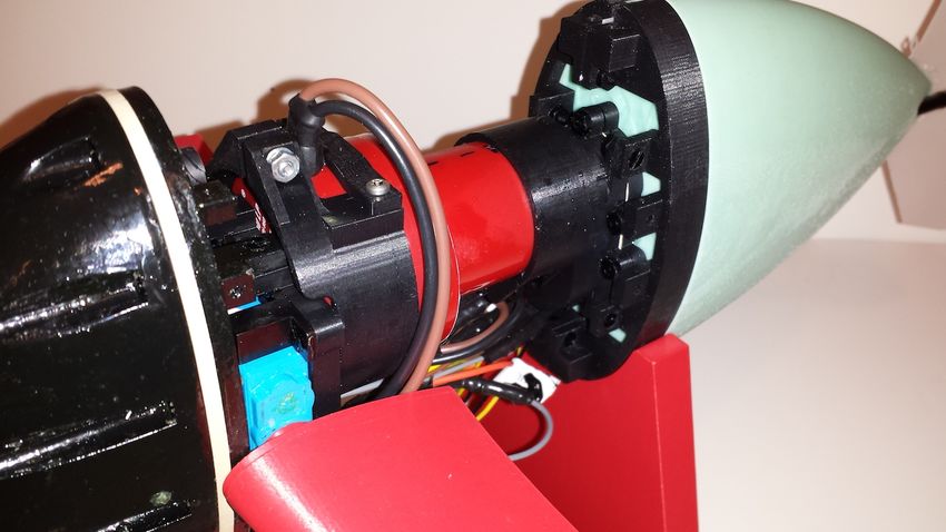
Hydraulic Autonomous Soft Fish for 3D Swimming         3

the principle of a passive, flexible mechanism driven by a traditional electrome-
chanical actuator. They are primarily designed to study the hydrodynamics of
the flexible body.
    There are also examples of compliant active-bodied robots that achieve fish-
like locomotion using distributed actuation. Shen et al. have used an oscillating
strip of ionic polymermetal composite as the posterior trunk of a dolphin-like
robot [19]. Suzumori et al. developed a soft-bodied manta using pneumatic ac-
tuation [20]. Both systems are free swimming robots, but are also limited by an
external tether.
    The Airacuda fish developed by Festo [21] uses tube-shaped pneumatic mus-
cles to actuate a flexible posterior body. The posterior body is composed of a
rigid plastic skeleton covered by flexible skin and has the two actuating muscles
at its center axis. In comparison, the posterior body presented in this work is
composed almost entirely of soft rubber with many fluidic elastomer actuators
embedded along both sides. The fluidic and electronic components of Airacuda
are located in the fishs rigid anterior. The Airacuda uses its pneumatic actuation
system not only for forward swimming and turning motions, but also for static
diving, whereas the hydraulic system presented in this work uses dive planes for
dynamic diving.
    The previous work by Marchese, Onal, and Rus [5] has a fluidic actuation
system that is embedded within the compliant and flexible body. This com-
pletely self-contained and autonomous system is capable of rapidly achieving
continuum-body motion, emulating forward swimming and planar escape ma-
neuvers of biological fish.

1.3   Extensions of Previous Work
This work extends in several ways the autonomous soft-bodied fish by Marchese,
Onal, and Rus [5]. In this previous work, it was demonstrated that soft robots
can be both self-contained and capable of rapid body motion. However, there
are several prohibitive shortcomings of this previous implementation. (1) The
fish used an open-circulation pneumatic actuation system that made prolonged
operation difficult; after energy was delivered to the distributed body actuators,
it was exhausted to the environment. This limitation is addressed in this paper
by designing a closed-circulation drive system. (2) The previous implementation
was pneumatically actuated without using an air bladder. The center of buoyancy
was therefore uncontrollably changing throughout the actuation cycle. Designing
the system to use water as a transmission fluid and being neutrally buoyant
addresses this use. (3) The previous implementation was constrained to move on
a pre-defined trajectory in two dimensions, which is addressed by introducing
dive planes to allow for dynamic diving.

1.4   Major Contributions
This work differs from previous work in that distributed hydraulic actuation, a
new drive system for this kind of actuation, and new fabrication techniques to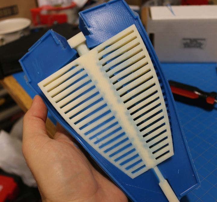
4       Hydraulic Autonomous Soft Fish for 3D Swimming

cast the distributed fluid elastomer actuator are used. Specifically, the following
contributions are made:

 1. Design of a water-driven soft-bodied actuator and a closed-circulation hy-
    draulic drive system;
 2. Fabrication technique for a soft-bodied actuator that allows arbitrarily formed
    fluidic channels, enabling a wide-range of continuous bending profiles;
 3. Biologically inspired fish-like gait and dynamic diving, enabling forward-
    swimming in 3D.

2   Technical Approach

The technical approach to develop an autonomously propulsing soft robotic fish
includes the mechanical design of individual functional units, a new fabrication
technique for fluidic elastomer actuators, and a control approach for the loco-
motion and steering of the fish.

Mechanical Design The robotic fish consists of three major functional com-
ponents. These are:

 1. the fish’s soft tail for forward propulsion and yaw motions,
 2. a waterproof gear pump unit as actuation source for the tail, and
 3. a pair of dive planes actuated by a waterproof servo to enable pitch control.

Furthermore, a dorsal and a ventral fin were added to protect the fish against
rolling. The control electronics are placed in a watertight nose compartment.
Figure 1 shows the robotic fish with all its major components.

Fish Tail The soft fish tail shown in Figure 2 belongs to the group of fluidic
elastomer actuators [2] [3]. The design mimics the rear portion of a fish, encom-
passing the posterior peduncle and the caudal fin. This tail can continuously
bend along its vertical center constraint layer by fluidic actuation of two lat-
eral cavity structures on each side. The inextensible and stiffer center constraint
layer splits the tail evenly along a vertical plane. An actuator consists of evenly
spaced ribs with hollow sections in between, connected by a center channel and
accessible by a front inlet. The rib structure allows for expansion or contraction
of the thin exterior skin under positive or negative fluidic pressure, respectively.
The sum of these expanding or contracting motions leads to bending of the
inextensible center constraint layer.

Fluidic Actuation Source Previous approaches with pneumatic actuation us-
ing compressed gas cartridges as an energy source allowed for fast propulsion,
but it was depleted after about 50 actuations [5]. Only a rather small compressed
gas cartridge fits into the self-contained fish robot. The energy to weight ratio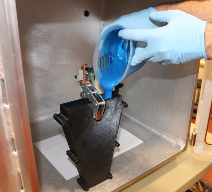
Hydraulic Autonomous Soft Fish for 3D Swimming        5

                   fluid elastomer           dorsal fin
                   actuator

                                                          gear pump

                                                              dive plane

      caudal fin

                   liquid
                            battery

                        ventral fin

                            electronics housing

                     Fig. 1: Isometric cut of fish assembly

of a compressed gas cartridge is lower than modern batteries. In order to de-
flate an actuator, all the gas inside it is exhausted to the environment without
reusing any of its kinetic energy. Furthermore, constantly releasing gas causes
non-neglible changes in the overall buoyancy of the robotic fish, which either
requires compensation through an air bladder or choosing a different actuation
approach. Alternately transporting fluid from one chamber to the other does not
require a storage unit in between, and the fluid does not need to be exhausted
in order to deflate the actuator. This motivated a closed circulation actuation
approach using an incompressible fluid like water and a gear pump to move it
back and forth. The gear pump including its actuating DC motor are shown in
Part B of Figure 3.
    The desired flapping frequency and curvature of the soft tail are determined
based on previous studies on self-propelling foils driven by an external robotic
actuator [22] [23]. The frequency and amplitude is applied onto a soft fish tail
using a hydraulic cylinder pump. The measurements on the displaced volume
and maximum pressures of the fish tail prototype combined with the desired
flapping frequency result in the desired volumetric flow rate. Based on those
results, a gear pump and its attached waterproof DC motor are designed and
specified. The volumetric displacement per shaft revolution of an external gear
pump is estimated with Q = π4 (D2 − d2 ) w, where w is the gear width, D is the
gear’s outer diameter, and d is the gear’s inner diameter [24].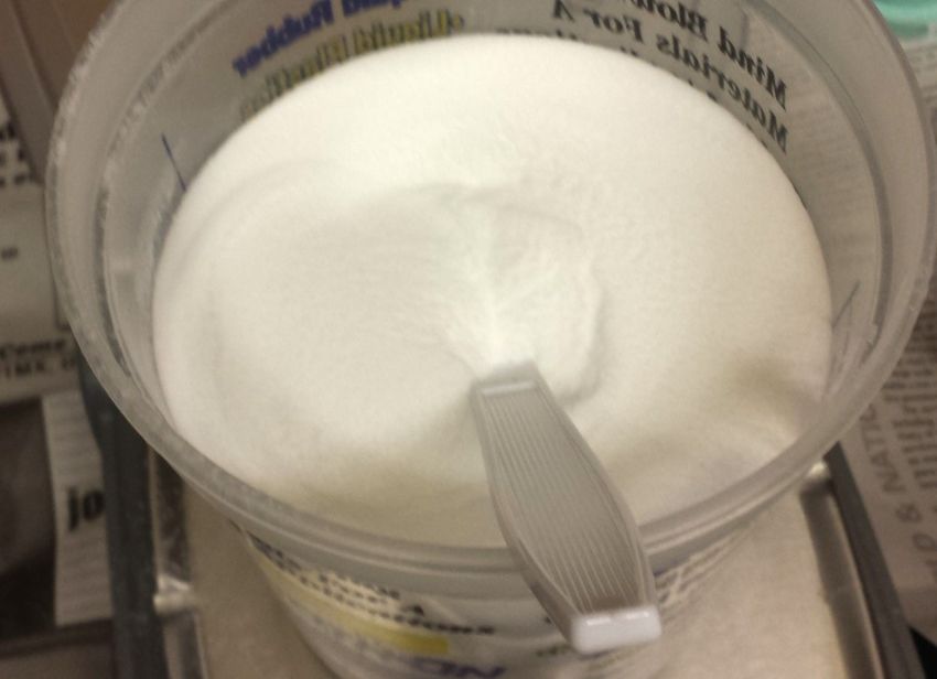
6          Hydraulic Autonomous Soft Fish for 3D Swimming

              center constraint layer
                                                                        left chamber

                                                           right
                                                           chamber
    outlet for initial
    priming
                                                         right front inlet
          center channel
                                                      head constraint
     ribs and hollow sections
                                                  left front inlet

Fig. 2: Fish’s soft tail as a fluidic elastomer actuator consisting of two fluidic
chambers, visualized with two different cut views.

                             A   clamp mount to      B
                                 DC motor                waterproof DC motor

                                                                      ball bearings   gear pump lid

servo motor
                                                  gear pump
                                                  housing                              pump outlets
                dive plane                                    gears                    to tail

Fig. 3: (A) Dive plane attached to waterproof servo and clamp mount, and (B)
gear pump with dc motor.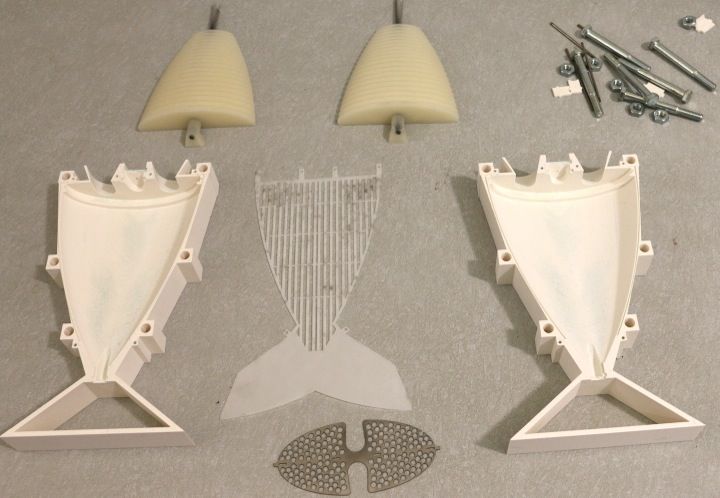
Hydraulic Autonomous Soft Fish for 3D Swimming                                            7

Dive Planes for Pitch Control In order to allow for pitch motion and there-
fore dynamic diving, a pair of servo actuated dive planes are designed and added
to the design at a place, where a fish’s pectoral fins are usually located. Pectoral
fins are responsible for the creation of a dynamic lifting forces to allow for depth
control. One dive plane including its clamp mount to the back of the DC motor
is shown in Part (A) of Figure 3. The dive plane profile is designed using a loft
limited by two symmetric air foil wing sections. A National Advisory Committee
for Aeronautics (NACA) 0013 profile with a cord length of 0.06 m and a NACA
0010 profile with a cord length of 0.025 m was used. The cord length was de-
termined by setting it to approximately 13% of the entire length of the body
of the fish. The thickness is defined by the size of the lever arm of the water-
proof servo, which in return defines the size of the mounting plate needed. A
symmetric profile is chosen so that no lift is produced when held in a horizontal
position.

2.1      Fish Tail Fabrication

The actuated cavities of the fish tail are achieved by lost-wax casting. The fab-
rication process is depicted in Figure 4.

            A       uncured
                    silicone
                                    B            cooled down                C
                                                                                        head
                                                                                      constraint
                     rubber                        wax core
                         rubber                                            wax core
                          mold

 outer                                                                                                            center
 mold                        outer mold
                                                                                                                constraint
                     lid                                       tail mold
                                                                  half                             spacer
                                                       E
                    D                                                        pin                            F
    uncured sili-
            sili                                                                                                fish tail
    cone rubber
    mixed with
    glass bubble

                                                                                                                 cooking pot
   assembled
    tail mold

                                          oven    cured fish tail   wax collecting
                                                  with wax core          pan

Fig. 4: Fish tail fabrication process: (A) Pour and cure a rubber mold, (B) pour
wax cores, (C) combine head constraint, center constraint and wax cores with
tail mold halves, (D) pour rubber mixed with glass bubbles into assembled tail
mold, (E) using an oven melt out wax core from the cured fish tail, and (F) cook
out remaining wax to create desired actuator cavities.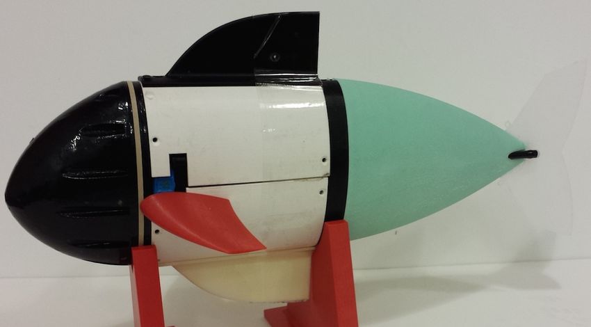
8       Hydraulic Autonomous Soft Fish for 3D Swimming

    In step (A), the rubber mold is poured and cured inside an assembly consist-
ing of an outer mold with lid and a model for the core inside of it. In preparation
for step (B), the lid and the model core are removed and the rubber mold is left
inside the outer mold. The rubber mold receives a small carbon fiber tube as an
inlay in its center cavity. This ensures that the wax core does not break when be-
ing removed from the rubber mold. Mold release spray is applied to the silicone
rubber mold to ease the wax core removal process. The wax is heated up until it
becomes fully liquefied. The assembly of rubber mold and outer mold is heated
up for a few minutes to the same temperature as the wax. Using a syringe, the
liquid wax is injected into the assembly. Within a few minutes, the injected wax
will start to solidify and significantly shrink in volume; this is counteracted by
injecting more hot wax into the solidifying wax core during the cool down. In
step (B), the wax core is first allowed to completely cool down, then it is released
from the mold. In step (C), a head constraint, a center constraint, and two wax
cores are assembled together inside the tail mold halves using spacers, position-
ing pins and screws. In step (D), a mix of silicone rubber with glass bubbles is
poured into the tail assembly and allowed to cure. In step (E), most of the wax
core is melted out by placing the fish tail in an upright position into an oven.
Finally, in step (F) the remaining wax residues are cooked out in a boiling water
bath.

2.2   Control
The motion control of the robotic fish is mainly determined by the propulsive for-
ward swimming motion of the soft tail. Yaw control is achieved through keeping,
on average, more fluidic volume in one fish half than the other. Pitch control
is done through adjusting the attack angle of the dive planes. Both yaw and
pitch control effort depend on the forward swimming speed by the tail. An on-
board 9 degrees of freedom inertial measurement unit provides absolute attitude
measurements, which will be used in a future version of the fish for closed-loop
attitude control.

Forward Swimming Controlling the speed of the gear pump determines the
volumetric flow from one side of the fin to the other. Alternating actuation
at approximately 1Hz results in a flapping motion of the posterior peduncle
and phase-shifted flapping of the caudal fin. The voltage profile of the motor is
shaped with an alternating trapezoidal profile to avoid impulsive switching, high
peak currents, and high angular momentum around the roll axis. To adjust the
forward swimming speed, the frequency and motor velocity are controlled.

Yaw Control Controlling the heading requires that the fish tail has an ad-
justable average offset from the neutral tail position. This can be achieved by
adjusting the alternating actuation so that on average more fluidic volume flows
into one fish half than the other. This can be done by (a) adjusting the amplitude
ratio between the positive and negative actuation trapezoid while keeping the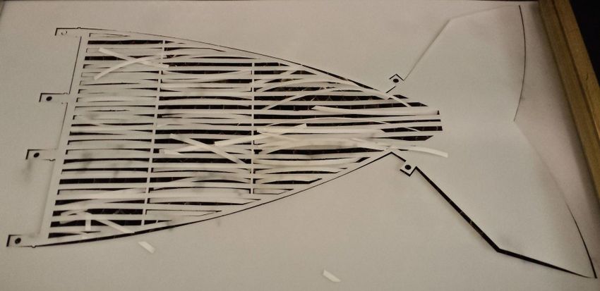
Hydraulic Autonomous Soft Fish for 3D Swimming            9

time duration of both trapezoids the same, or (b) adjusting the ratio of time du-
ration of both trapezoids so that one half is filled up longer than the other. The
latter approach was chosen for the fish presented in this work. A combination of
both methods is also possible.

Pitch Control Controlling the pitch of the fish is achieved through adjusting
the attack angle of the dive planes in a range of − π4 rad to π4 rad. The forward
swimming speed directly determines how fast the pitch of the fish is changed
and can be maintained.

3   Results
The implemented fabrication process for the wax is depicted in Figure 5, showing
each major step from silicone rubber mold creation to de-molding of the wax
core. The outer mold, the lid, and the model core are 3d printed. The silicone
rubber mold has an A30 durometer. Beeswax with a melting point of 63◦ C is
heated up to 95◦ C for pouring into the rubber mold.

 (a) 3d printed model core   (b) Create silicone mold     (c) Release model core

(d) Heating wax and mold     (e) Pour wax with syringe   (f) Demolding of wax core

                    Fig. 5: Fabrication steps of the wax core

    The titanium head constraint was water jetted out of a 0.9 mm thick highly
corrosion-resistant grade 2 titanium plate. The center constraint was laser cut
out of a 0.5 mm thick flexible acetal sheet. Both fabrication steps are depicted
in Figure 6.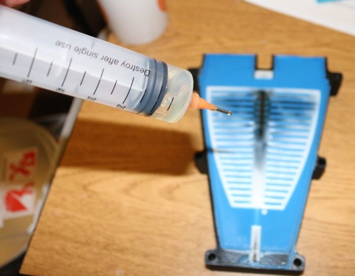
10        Hydraulic Autonomous Soft Fish for 3D Swimming

       Fig. 6: Laser cut center constraint layer and water jet head constraint

   In the final fabrication steps, two wax cores and both constraint layers are
combined with the fish tail molds. The steps are depicted in Figure 7.

     (a) Individual parts of tail (b) Assembling the tail   (c) Mixing of silicone rub-
     mold assembly                mold parts                ber and glass bubbles

     (d) Degassing and curing (e) Melting out the wax       (f) Cooking out residues
     silicone rubber fish tail core in an oven              of wax

             Fig. 7: Final fabrication steps of the silicone rubber fish tail

    The tail consists of A15 durometer silicone rubber mixed with low density
crush resistant glass bubbles to achieve a mixed density just below the density
of water. The mixing ratio, nb , between the bubble mass, mb , and the silicone
rubber mass, ms , is: nb = m   mb
                                s
                                   = (1 − ρρds )/( ρρdb − 1), where ρb stands for the
density of the glass bubbles, ρs stands for the density of the silicone rubber, and
ρd stands for the desired mixed density. The density of the used silicone rubber
is ρs = 1.18 g/cm3 and the density of the glass bubbles is ρb = 0.125 g/cm3 . In
order to make the fish tail slightly lighter than water, a desired mixed density of
ρd = 0.991 g/cm3 with a mixing ratio of nb = 2.3% is used. This mixing step is
important for achieving overall neutral buoyancy of the robotic fish. Otherwise,
Hydraulic Autonomous Soft Fish for 3D Swimming 11
the weight of the fish tail has to be compensated with thick styrofoam flotation
attachments around the center of the fish, which introduces undesired drag.
The nose of the fish is a waterproof housing for the microcontroller, mo-
tor driver, and wireless communication electronics. The housing is 3D printed
and waterproofed by brush-coating it with a polyurethane paint and subsequent
degassing [25]. Behind the nose is the dive plane assembly, consisting of two
individually controllable dive plane units. Each unit consists of a dive plane,
which is directly mounted onto the lever arm of a waterproof servo motor. The
dive plane assembly is mounted to the end of the brushed DC motor of the gear
pump. The motor and gear pump unit is directly attached to the soft fish tail.
Underneath the gear pump motor sits a lithium polymer battery to power all
components.
Each actuator has a removable plug at the caudal fin: the initial dive is
started with plugs removed so water can fill the actuation chambers by running
the self-priming gear pump at a low frequency for a short duration. After all air
has been removed, the plugs are inserted to seal the chambers.
The 1.65 kg mass of the complete assembly was slightly adjusted to make it
almost neutrally buoyant using foam attachments and additional weights placed
outside and inside the 3D printed center hull of the fish. The fish has the dimen-
sions: 0.45 m x 0.19 m x 0.13 m.
The fish receives 72MHz wireless communication commands to move forward,
move up and down, or turn left and right. The on-board micro-controller trans-
lates these high-level commands into the control law for the tail actuation and
the angular positions of the dive planes.
The assembled fish with and without outer hulls is shown in Figure 8.
Fig. 8: Fully assembled soft robotic fish with and without outer hulls
4 Experiments
The goal of the experiments is to show the capabilities of the soft robotic fish in
continuous forward swimming and pitch control, using a single battery loading.
Additionally, yaw control was demonstrated in the pool experiments.12 Hydraulic Autonomous Soft Fish for 3D Swimming
4.1 Fish Tank Experiments
The fish swam in a tank of a length of 1.22 m in a straight, horizontal line from
wall to wall and repeated this 25 times. It was manually placed back to the start
after each completion of one lap.
Fig. 9: Fish Tank Experiment: Forward Swimming
For an average horizontal distance of 0.74 m, the horizontal swimming speed
was 0.10 m/s, which is equivalent to 0.15 body lengths per second. One repetition
of the horizontal forward swimming experiment is shown in Figure 9.
To test the pitch control, the fish’s submergence was adjusted as it moved
forward over the span of the tank by setting the pitch angle of the dive planes
to π4 rad. For 13 repetitions of this experiment, the average diving speed was
0.015 m/s over an average vertical distance of 0.13 m. The horizontal swimming
speed was 0.08 m/s over an average horizontal distance of 0.74 m. One repetition
of the diving experiment is shown in Figure 10.
Fig. 10: Fish Tank Experiment: Diving
After 35 minutes of continuous wireless underwater operation, the 1.3 Ah
lithium polymer battery was almost depleted. This corresponded to 52 repeated
runs through the tank, resulting in a total distance of approximately 40 m.Hydraulic Autonomous Soft Fish for 3D Swimming 13
4.2 Pool Experiments
In a 13.25 m x 7 m x 1.12 m pool, the maximum horizontal swimming speed was
0.23 body lengths per second. One trial of the horizontal forward swimming
experiment in the pool is shown in Figure 9. The figure shows overlaid fish’s
poses for every time it had moved for one full body length.
To test the pitch control, the fish’s submergence was adjusted as it moved
near the side wall of the pool. The pitch angle of the dive planes was set to
approximately π4 rad. One trial of the diving experiment in the pool is shown in
Figure 11b.
The heading or yaw control was also tested. The fish was able to turn in the
pool, as can be seen in Figure 11c.
(b) Diving
(a) Forward Swimming (c) Turning
Fig. 11: Pool experiments demonstrating locomotion capabilities14 Hydraulic Autonomous Soft Fish for 3D Swimming
After about 40 minutes of continuous operation in the pool and swimming
an accumulative distance of approximately 130 m, the 1.3 Ah lithium polymer
battery was almost depleted.
5 Main Experimental Insights
The approach proposed in this work for creating an autonomous soft-bodied
robotic fish resulted in a robot that demonstrated prolonged and consistent
underwater operation. While most soft robots are pneumatically powered, it
was shown that hydraulic power increases the capabilities for a given range of
applications. For example, when high frequency change of actuation direction
is needed, exemplified by the flapping foil, or prolonged actuation of an au-
tonomous soft robot is required. Hydraulic actuation allows for a higher force as
shown by the overcoming of hydrodynamic resistance used for the fish-like lo-
comotion [26]. The presented prototype is a step towards creating a closed-loop
controlled biomimetic robotic fish which is inherently soft, performs continuous
body deformations from nose to tail, and allows for safe interaction with other
living beings. Based on the experimental results, the novel actuation system of
the robot prototype will influence future work in the field, both in terms of fish
robots and soft robots in general.
References
1. Albu-Schaffer, A., Eiberger, O., Grebenstein, M., Haddadin, S., Ott, C., Wimbock,
T., Wolf, S., Hirzinger, G.: Soft robotics. Robotics & Automation Magazine, IEEE
15(3) (2008) 20–30
2. Correll, N., Onal, C.D., Liang, H., Schoenfeld, E., Rus, D.: Soft autonomous
materials - using active elasticity and embedded distributed computation. In:
12th International Symposium on Experimental Robotics (ISER), New Delhi, India
(2010)
3. Onal, C.D., Chen, X., Whitesides, G.M., Rus, D.: Soft mobile robots with on-board
chemical pressure generation. In: International Symposium on Robotics Research
(ISRR). (2011)
4. Marchese, A.D., Onal, C.D., Rus, D.: Soft robot actuators using energy-efficient
valves controlled by electropermanent magnets. In: Intelligent Robots and Systems
(IROS), 2011 IEEE/RSJ International Conference on, IEEE (2011) 756–761
5. Marchese, A.D., Onal, C.D., Rus, D.: Autonomous soft robotic fish capable of
escape maneuvers using fluidic elastomer actuators. Soft Robotics 1(1) (2014)
6. Barrett, D.S.: Propulsive efficiency of Robotuna. PhD thesis, PhD thesis, Mas-
sachusetts Institute of Technology (1988)
7. Triantafyllou, M.S., Triantafyllou, G.S.: An efficient swimming machine. Scientific
american 272(3) (1995) 64–71
8. Zhong, Y., Chong, C., Zhou, C., Seet, G.G., Low, K.: Performance predict model
for a body and caudal fin (bcf) biomimetics fish robot. In: International Conference
on Advanced Intelligent Mechatronics, IEEE/ASME (2009) 1230–1235
9. Liu, J., Hu, H.: Biological inspiration: from carangiform fish to multi-joint robotic
fish. Journal of Bionic Engineering 7(1) (2010) 35–48Hydraulic Autonomous Soft Fish for 3D Swimming 15
10. Wen, L., Wang, T., Wu, G., Liang, J.: Hydrodynamic investigation of a self-
propelled robotic fish based on a force-feedback control method. Bioinspiration &
Biomimetics 7(3) (2012) 036012
11. Rossi, C., Colorado, J., Coral, W., Barrientos, A.: Bending continuous structures
with smas: a novel robotic fish design. Bioinspiration & Biomimetics 6(4) (2011)
045005
12. Trivedi, D., Rahn, C.D., Kier, W.M., Walker, I.D.: Soft robotics: Biological inspi-
ration, state of the art, and future research. Applied Bionics and Biomechanics
5(3) (2008) 99–117
13. Laschi, C., Cianchetti, M., Mazzolai, B., Margheri, L., Follador, M., Dario, P.: Soft
robot arm inspired by the octopus. Advanced Robotics 26(7) (2012) 709–727
14. El Daou, H., Salumae, T., Ristolainen, A., Toming, G., Listak, M., Kruusmaa, M.:
A bio-mimetic design and control of a fish-like robot using compliant structures. In:
Advanced Robotics (ICRA), 2011 15th International Conference on, IEEE (2011)
563–568
15. El Daou, H., Salumae, T., Toming, G., Kruusmaa, M.: A bio-inspired compliant
robotic fish: Design and experiments. In: Robotics and Automation (ICRA), 2012
IEEE International Conference on, IEEE (2012) 5340–5345
16. Valdivia y Alvarado, Pablo; Youcef-Toumi, K.: Design of machines with compli-
ant bodies for biomimetic locomotion in liquid environments. ASME Journal of
Dynamics Systems Measurement and Control 128 (March 2006) 3–13
17. Long, J.H., Koob, T., Schaefer, J., Summers, A., Bantilan, K., Grotmol, S., Porter,
M.: Inspired by sharks: a biomimetic skeleton for the flapping, propulsive tail of
an aquatic robot. Marine Technology Society Journal 45(4) (2011) 119–129
18. Long, J.H., Krenitsky, N.M., Roberts, S.F., Hirokawa, J., de Leeuw, J., Porter,
M.E.: Testing biomimetic structures in bioinspired robots: how vertebrae control
the stiffness of the body and the behavior of fish-like swimmers. Integrative and
comparative biology 51(1) (2011) 158–175
19. Shen, Q., Wang, T., Liang, J., Wen, L.: Hydrodynamic performance of a biomimetic
robotic swimmer actuated by ionic polymer–metal composite. Smart Materials and
Structures 22(7) (2013) 075035
20. Suzumori, K., Endo, S., Kanda, T., Kato, N., Suzuki, H.: A bending pneumatic
rubber actuator realizing soft-bodied manta swimming robot. In: International
Conference on Robotics and Automation, IEEE (2007) 4975–4980
21. Festo: Airacuda. http://www.festo.com/cms/en_corp/9761.htm (2006) Accessed:
2014-05-24.
22. Lauder, G.V., Flammang, B., Alben, S.: Passive robotic models of propulsion by
the bodies and caudal fins of fish. Integrative and comparative biology 52(5) (2012)
576–587
23. Alben, S., Witt, C., Baker, T.V., Anderson, E., Lauder, G.V.: Dynamics of freely
swimming flexible foils. Physics of Fluids (1994-present) 24(5) (2012) 051901
24. Karassik, I.J., Messina, J.P., Cooper, P., Heald, C.C.: Pump Handbook. Volume 4.
McGraw-Hill New York (2008)
25. Mireles, J., Adame, A., Espalin, D., Medina, F., Winker, R., Hoppe, T., Zinniel,
B., Wicker, R.: Analysis of sealing methods for fdm-fabricated parts. Technical
report, W.M. Keck Center for 3D Innovation. The Univ. of Texas, El Paso (2011)
26. Drucker, E.G., Lauder, G.V.: Locomotor forces on a swimming fish: three-
dimensional vortex wake dynamics quantified using digital particle image velocime-
try. Journal of Experimental Biology 202(18) (1999) 2393–2412You can also read