Implementing Remote Customer Service API using WebRTC and Jitsi SDK - Aaltodoc
←
→
Page content transcription
If your browser does not render page correctly, please read the page content below

Implementing Remote Customer
Service API using WebRTC
and Jitsi SDK
Markus Kullberg

School of Science

Thesis submitted for examination for the degree of Master of
Science in Technology.
Espoo 29.7.2018

Supervisor

                             Prof. Petri Vuorimaa

Advisor
                             M.Sc. (Tech.), M.Sc. (Econ.)
                             Harri Jokela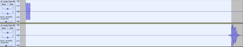
Copyright © 2018 Markus Kullberg
Aalto University, P.O. BOX 11000, 00076 AALTO
                                                                         www.aalto.fi
                                                       Abstract of the master’s thesis

Author Markus Kullberg
Title Implementing Remote Customer Service API using WebRTC
     and Jitsi SDK
Degree programme Computer, Communication and Information Sciences
Major Computer Science                                       Code of major SCI3042
Supervisor Prof. Petri Vuorimaa
Advisor M.Sc. (Tech.), M.Sc. (Econ.) Harri Jokela
Date 29.7.2018              Number of pages 8+54                  Language English
Abstract
WebRTC and SIP open up new interesting possibilities to combine legacy phone
systems and the PSTN directly with web applications. In this thesis I examine
how such an application can be built using Open Source Software and a SIP trunk.
The application is mainly directed towards customer service as a way to integrate
video calls in contact center solutions. The technologies and components behind the
application are explained before delving into implementation details. Problems faced
along the way when developing the application are presented along with solutions to
them.
   Since the audio in a video call travels via the PSTN and is therefore not sent
over the IP network in its entirety, there exists audio/video synchronization error.
To quantify the differential delay, the latency of audio and video was measured.
The results show that audio is delayed w.r.t. video by 150-320 ms, depending on
various factors. This range is partly within the acceptable threshold of 240 ms,
which is defined by previous studies. The test results also show that using a VoLTE
connection and the PCMA codec minimizes audio delay.
Keywords WebRTC, PSTN, SIP, customer service, contact center, lip sync
Aalto-universitetet, PB 11000, 00076 AALTO
www.aalto.fi
sammandrag av diplomarbetet
Författare Markus Kullberg
Titel Implementering av en API för användning inom kundtjänst med hjälp av
WebRTC och Jitsi SDK
Utbildningsprogram Computer, Communication and Information Sciences
Huvudämne Computer Science Huvudämnets kod SCI3042
Övervakare Prof. Petri Vuorimaa
Handledare DI, EM Harri Jokela
Datum 29.7.2018 Sidantal 8+54 Språk Engelska
Sammandrag
WebRTC och SIP öppnar nya intressanta möjligheter att kombinera äldre telefon-
system och det publika telefonnätet (PTN) direkt med webbapplikationer. I denna
avhandling undersöker jag hur en sådan applikation kan byggas med hjälp av en
SIP trunk och programvaror med öppen källkod. Applikationen är främst avsedd för
användning inom kundtjänst som ett sätt att integrera videosamtal i en kontaktcenter-
lösning. Teknologierna och komponenterna bakom applikationen samt detaljerna av
implementeringen beskrivs. Motgångar som uppstod under applikationens utveckling
samt reflektioner över för- och nackdelar kring olika tillvägagångssätt presenteras.
I och med att ljudet i ett videosamtal rör sig via PTN och därmed inte skickas
över IP-nätverket i dess helhet, är synkroniseringen av ljud och video ett problem.
För att kvantifiera synkroniseringsfelet mätte jag födröjningen av video och ljud.
Resultaten visar att ljudet är försenat till video med 150-320 ms, beroende på olika
faktorer. Detta intervall ligger delvis inom det godtagbara tröskelvärdet på 240 ms,
som är fastsällt av tidigare studier. Testresultaten visar också att användning av en
VoLTE-anslutning och PCMA-kodning minimerar ljudfördröjningen.
Nyckelord WebRTC, PTN, SIP, kundtjänst, kontaktcenter, läppsynk5
Preface
I want to thank Prof. Petri Vuorimaa for giving me free hands to write my thesis the
way I wanted. I also want to thank you for your invaluable feedback and suggestions
when I was not sure what to do next.
I wish to thank my advisor and colleague Harri Jokela for helping me devise my
thesis subject and for taking me into your team at Telia Finland to work on this
application. It has been a very interesting project and has taught me a great deal
about software development.
Thank you Daniel Bruzual for suggesting the latency measurement tests when I
struggled to come up with my own ideas. Without your help I would probably still
be stuck writing this thesis.
Lastly, I wish to thank my colleague Jaakko Lehtinen for spending your time to
read through my thesis multiple times to give me feedback. Having just finished your
own thesis, your input was very valuable.
Otaniemi, 29.7.2018
Markus H. F. Kullberg6
Contents
Abstract 3
Abstract (in Swedish) 4
Preface 5
Contents 6
Abbreviations 8
1 Introduction 1
1.1 Research scope . . . . . . . . . . . . . . . . . . . . . . . . . . . . . . 1
1.2 Research questions . . . . . . . . . . . . . . . . . . . . . . . . . . . . 2
1.3 Goal . . . . . . . . . . . . . . . . . . . . . . . . . . . . . . . . . . . . 2
1.4 Structure . . . . . . . . . . . . . . . . . . . . . . . . . . . . . . . . . 2
2 Background 3
2.1 WebRTC as a Unified Communications Platform . . . . . . . . . . . . 3
2.2 Signaling . . . . . . . . . . . . . . . . . . . . . . . . . . . . . . . . . . 4
2.2.1 SDP . . . . . . . . . . . . . . . . . . . . . . . . . . . . . . . . 4
2.2.2 SIP . . . . . . . . . . . . . . . . . . . . . . . . . . . . . . . . . 6
2.2.3 Jingle . . . . . . . . . . . . . . . . . . . . . . . . . . . . . . . 7
2.3 Telephony Networks and VoIP . . . . . . . . . . . . . . . . . . . . . . 11
2.3.1 PBX and SIP Trunking . . . . . . . . . . . . . . . . . . . . . 12
2.4 WebRTC . . . . . . . . . . . . . . . . . . . . . . . . . . . . . . . . . . 13
2.4.1 API . . . . . . . . . . . . . . . . . . . . . . . . . . . . . . . . 14
2.4.2 Codecs . . . . . . . . . . . . . . . . . . . . . . . . . . . . . . . 16
2.4.3 ICE . . . . . . . . . . . . . . . . . . . . . . . . . . . . . . . . 18
2.5 Contact center software . . . . . . . . . . . . . . . . . . . . . . . . . . 18
2.6 WebRTC frameworks . . . . . . . . . . . . . . . . . . . . . . . . . . . 21
2.7 Jitsi . . . . . . . . . . . . . . . . . . . . . . . . . . . . . . . . . . . . 22
2.7.1 Jitsi Meet . . . . . . . . . . . . . . . . . . . . . . . . . . . . . 23
2.7.2 Jitsi Videobridge . . . . . . . . . . . . . . . . . . . . . . . . . 23
2.7.3 Jicofo . . . . . . . . . . . . . . . . . . . . . . . . . . . . . . . 25
2.7.4 Jigasi . . . . . . . . . . . . . . . . . . . . . . . . . . . . . . . 27
2.8 Callstats . . . . . . . . . . . . . . . . . . . . . . . . . . . . . . . . . . 28
2.9 Related work . . . . . . . . . . . . . . . . . . . . . . . . . . . . . . . 28
3 Implementation 30
3.1 Requirements . . . . . . . . . . . . . . . . . . . . . . . . . . . . . . . 30
3.2 Architecture . . . . . . . . . . . . . . . . . . . . . . . . . . . . . . . . 31
3.3 Jitsi modifications . . . . . . . . . . . . . . . . . . . . . . . . . . . . . 32
3.4 Security and authentication . . . . . . . . . . . . . . . . . . . . . . . 33
3.5 Issues and workarounds . . . . . . . . . . . . . . . . . . . . . . . . . . 357 4 Measurements 38 4.1 Results . . . . . . . . . . . . . . . . . . . . . . . . . . . . . . . . . . . 42 5 Discussion 51 6 Summary 54 Appendices A Appendix 60
8

Abbreviations
API     Application Programming Interface
CSRC    Contributing Source (Identifier)
DTLS    Datagram Transport Layer Security
ICE     Interactive Connectivity Establishment
IETF    Internet Engineering Task Force
JSEP    JavaScript Session Establishment Protocol
JWT     JSON Web Token
MCU     Multipoint Control Unit
NAT     Network Address Translation
LTE     Long-Term Evolution
OSS     Open Source Software
P2P     Peer-To-Peer
PBX     Private Branch Exchange
PCM     Pulse Code Modulation
PCMA    PCM A-law
PSTN    Public-Switched Telephony Network
RTC     Real-Time Communications
RTCP    Real-Time Transport Control Protocol
RTP     Real-Time Protocol
SBC     Session Border Controller
SDP     Session Description Protocol
SFU     Selective Forwarding Unit
SIP     Session Initiation Protocol
SRTP    Secure Real-Time Protocol
STUN    Session Traversal Utilities for NAT
TDM     Time Division Multiplexing
TURN    Traversal Using Relays around NAT
VoIP    Voice over IP
VoLTE   Voice over LTE
W3C     World Wide Web Consortium
1        Introduction
Web Real-Time Communications (WebRTC) is a technology, which allows web
applications to capture and stream audio and/or video media as well as arbitrary
data over the Internet without the need for third-party plugins. In other words,
the browser can request access to the user’s microphone and web camera, enabling
video calling and file transfer functionality to other browsers. An interesting use case
for WebRTC is the integration with other communications platforms, such as the
telephone network. Integrating voice over IP (VoIP) with legacy telephone systems
is not a new invention; for example, the renown VoIP application Skype has been
able to place calls to the telephone network since long ago. However, integrating a
WebRTC application with the telephone network eliminates the need to install an
external application such as Skype, since it runs in the browser. This opens up many
different possibilities for new services.
    One use case is in customer service; when the customer browses a company’s
website he no longer needs the customer service’s phone number or his own phone.
The company can embed a button on the website, which starts a call using WebRTC
to the customer service, without the user having to leave the website. On top of this,
it is easy to add video or chat functionality to the WebRTC application, opening
up possibilities for screen sharing and more. This would not be possible using the
telephone network alone.
    One might wonder why it is important to integrate WebRTC with the telephone
network - why not just use WebRTC at both ends? The reason in this use case is
that customer services are heavily invested in their customer service software, which
are often based on the legacy telephone network. These software implement functions
such as call queueing, reporting, recording and more. Also, even though VoIP
performance is constantly improving, the performance and stability of traditional
phone calls are still better than VoIP calls. Therefore, customer services cannot
move away from these systems, so interoperable systems are needed.
    WebRTC is royalty and license free, which means that companies can save a
significant amount of money compared to other video conferencing solutions. In this
thesis I discuss the background technologies and propose a service based on an Open
Source Software (OSS) for companies to integrate in their customer service.

1.1       Research scope
The purpose of this thesis is to present a solution for enterprises to embed video
customer service in their website. The service is built with the OSS Jitsi Meet1 ,
which utilizes WebRTC. The thesis takes on a practical approach, explaining the
process of creating and setting up the application and rationalizing the choices made.
Focus is set on integrating WebRTC with the PSTN for use within customer service.
Latency measurements of video and audio are also presented to identify lip sync
problems in the service.
    1
        https://jitsi.org/jitsi-meet/
2
1.2 Research questions
The following questions were used as a base for the thesis:
• How to connect WebRTC with the PSTN?
• How to integrate WebRTC-powered video real-time communication with contact
center software?
• Why did I choose the Jitsi Meet as my WebRTC SDK?
• What is the latency difference between audio and video in a WebRTC-PSTN
video call?
1.3 Goal
The following points summarize the goal of the thesis:
• Description of an implementation to integrate video real-time communications
with contact center software
• Audio/video differential delay measurement of the application with analysis
1.4 Structure
The thesis is laid out as following. In this section, the reader was introduced to the
thesis subject and the motivation behind the thesis was laid out. In Section 2, the
key technologies behind VoIP and WebRTC are explained. An introduction to the
WebRTC API is also given. In addition to this, I describe contact center software
and explain how WebRTC can be integrated with them. Then, I discuss the purpose
of WebRTC SDKs/frameworks and motivate why I chose Jitsi. Finally, I describe
the components that Jitsi consists of and discuss related work.
In Section 3, I show how I was able to build a WebRTC video calling application
on top of Jitsi Meet, suitable for enterprises to integrate in their customer service. I
discuss the architecture of the application, describe what modifications was needed
in Jitsi and lastly I present issues related to security and authentication and explain
how I solved them.
In Section 4, the measurement methods used in the thesis are presented. I measure
the latency of both the video and audio streams using different scenarios. I then
present the results of the tests. In the following section, I analyze the results and
compare the values to thresholds as identified by several standard bodies and already
conducted research.
Finally, in Section 6, I summarize the thesis and present ideas for future work.3
2 Background
2.1 WebRTC as a Unified Communications Platform
Before the emergence of WebRTC, video conferencing required specialized software
to be installed on client machines. Major players in this business are Cisco with their
WebEx and Spark products, and Microsoft with their Teams product. The products
offer a rich amount of services, including video conferencing rooms with file sharing
features, desktop, presentation and dissemination. With WebRTC it is possible to
do all of this without the need of installing third-party software. All of the major
browsers (Chrome, Firefox, Opera, Edge, Safari) support WebRTC, so as long as
the client has one of these browsers installed they can use WebRTC. Best of all,
in the simplest peer-to-peer scenario, a simple JavaScript application is enough for
establishing a connection without the need for a media server.
The benefits of using WebRTC as a unified communications platform are many.
The first one, which plays an important role for enterprises, is the cost savings
compared to commercial products such as the ones mentioned in the previous
paragraph. For small businesses that require occasional videoconferencing, there
exists several free WebRTC video conference applications that are hosted, such as
Google’s AppRTC2 and Atlassian’s Jitsi Meet3 . If security is a concern, it is also
possible for the enterprise to host the application themselves. The second benefit, as
already mentioned, is the elimination of third-party software. For large enterprises
it can require much effort to manage and update the software on every employee’s
computer. A third benefit is that the end user can use his own SIP trunk for telephone
services if he already has one, and not rely on, e.g., Cisco infrastructure and therefore
their rates. A fourth benefit is that developing a communications platform has never
been easier than now, when there exists open and well-defined APIs and tutorials.
Before WebRTC, most communications software were closed software, so enterprises
were almost forced to buy instead of developing themselves.
Not only does WebRTC help in corporate usage, but it also favors everyday
users. Popular video conferencing applications for everyday users include Skype and
Google Hangouts. With the emergence of WebRTC, they are now also available as
web applications4,5 , so they no longer require you to install the application. This
shows that WebRTC is also a technology, which favors already established unified
communications service providers, rather than being a competitive technology. In
the gaming scene, Discord6 has revolutionized voice communication. Before Discord
existed, gamers had many VoIP applications to choose from: TeamSpeak, Ventrilo,
Skype and Mumble, to name a few. Many users dislike cluttering their operating
system with many different apps that serve the same purpose. Each person had their
own preference and their own server, often resulting in frustration when trying to
2
https://appr.tc
3
https://meet.jit.si
4
https://web.skype.com
5
https://hangouts.google.com
6
https://discordapp.com/4
agree on a common application. After Discord made its way into the scene, users
quickly moved over to it. This is a prime example of how WebRTC can revolutionize
real-time communication.
2.2 Signaling
Signaling is the process of coordinating communication between two or more peers
over the Internet. Signaling is needed in the context of real-time communications to
first connect the peers who wish to communicate with each other. Without signaling,
the real-time application does not know where to send data and in what format.
Sam Dutton summarizes what information is exchanged via the signaling service [1]:
– Session control messages used to open or close communication
– Error messages
– Media metadata, such as codecs and codec settings, bandwidth and media
types
– Key data, used to establish secure connections
– Network data, such as a host’s IP address and port as seen by the outside world
A visualization of the signaling architecture is given in Figure 1. It can be seen
from the figure that without signaling it would not be possible to connect the two
browsers. Apart from opening and closing the communication, signaling is also used
for sending control messages such as pausing or muting a call.
Two popular signaling protocols are Session Initiation Protocol (SIP) and Jingle,
which is a signaling extension for XMPP. In WebRTC applications, it is not unusual to
create your own signaling protocol. Custom signaling solutions often use WebSockets
or Ajax as the communication protocol.
2.2.1 SDP
Session Description Protocol (SDP) [2] is a protocol for describing multimedia
sessions for the purposes of session announcement, session invitation, and other
forms of multimedia session initiation. SDP is needed to convey information about
media details, transport addresses, and other session description metadata to the
participants. The protocol is independent of transport protocols to support as many
scenarios as possible.
In a nutshell, SDP defines a format for exchanging the information mentioned
before. An SDP object is a message consisting of types and values, separated by an
equal sign. Every "type" starts on a newline and its "value" can have many lines. An
example SDP message is given in Listing 1.
Listing 1: Example SDP message.
v=05
o=j d o e 2890844526 2890842807 IN IP4 1 0 . 4 7 . 1 6 . 5
s=SDP Seminar
i=A Seminar on th e s e s s i o n d e s c r i p t i o n p r o t o c o l
u=http : / /www. example . com/ s e m i n a r s / sdp . pdf
e=j . doe@example . com ( Jane Doe )
c=IN IP4 2 2 4 . 2 . 1 7 . 1 2 / 1 2 7
t =2873397496 2873404696
a=r e c v o n l y
m=audio 49170 RTP/AVP 0
m=v i d e o 51372 RTP/AVP 99
a=rtpmap : 9 9 h263 −1998/90000
The most important part of the SDP description with regard to WebRTC are the
"a" and "m" types. These types contain information about the media that is to be
transferred and how, i.e., if the media is audio or video, what codec is used, which
transport protocol to use along with the network ports. The importance of these
fields and how WebRTC makes use of them in the signaling process will become clear
later in this thesis.
Signaling
Signaling
Application Application
Session Description Session Description
Media
Figure 1: Signaling overview.6
2.2.2 SIP
Session Initiation Protocol (SIP) [3] is an application-layer protocol for initiating,
modifying and terminating multimedia sessions, such as video and voice calls over
the Internet. SIP borrows characteristics from Hypertext Transfer Protocol (HTTP)
and Simple Mail Transfer Protocol (SMTP). SIP messages consist of a set of header
fields, both optional and mandatory. The protocol follows a request-response pattern
(like HTTP) and features status codes. SIP is not tied to any particular transport
protocol, so it can be used with transport protocols like TCP and UDP.
A typical SIP call flow is visualized in Figure 2. This is called the SIP trapezoid
because of its geometric shape. The SIP connection is started by one of the parties
(Alice) by sending a SIP message to the other party (Bob) with the INVITE method
in the first line of the message. The INVITE row contains Bob’s SIP Uniform
Resource Identifier (URI), which uniquely identifies him. A SIP URI has the form
sip:username@domain, e.g., sip:bob@aalto.fi. Alternatively, if the SIP messages are
to be secured over Transport Layer Security (TLS), the SIPS URI scheme [4] is used.
The SIP message is sent to Alice’s SIP proxy, which uses DNS to locate Bob’s proxy,
and forwards it. After the message reaches Bob’s proxy, his location is resolved and
finally the message is sent to him.
At each step, when the messages passes through a proxy (there might be more
than just the two visualized), an Answer message is sent back to the previous sender.
In the case of the INVITE method, the TRYING method is sent back, to give the
initiator some feedback. It is up to the application to decide what to do with this
message, e.g., showing a message on Alice’s screen that the call is being established.
After the INVITE message reaches Bob, he sends back a Ringing message to
Alice to signal that the invite has reached him and he is now considering whether
to answer or to decline. Typically, Alice’s application would start playing a ringing
sound at this point. When Bob accepts the call, an OK message is sent to Alice.
The OK message contains Bob’s SDP, which tells, e.g., what audio and video codecs
he prefers. After the message reaches Alice, she replies with an ACK, following the
request-reply pattern. Alice’s SDP was sent with the initial INVITE message. Now
that Alice and Bob know each others’ SDPs, they can start sending media. The
media along with the ACK message are sent directly between the call participants,
since they now know each others’ network addresses. This means that the proxies
are only used for establishing the call.
After Alice and Bob are done communicating, either of them can end the call by
sending a BYE message. The other party receives the message and replies with an
OK message. This concludes the SIP call.
SIP messages consist of more than just the method row as described earlier. After
the method, a number of header fields exist. A header field is a named attribute
that provide additional information about the message. For example, an INVITE
message contains at least the following header fields: Via, Max-Forwards, To, From,
Call-ID, CSeq, Contact, Content-Type and Content-Length. In addition to header
fields, a message body also exists in a SIP message, much like a HTTP body. The
type of message content is specified by the Content-Type header field, and in the7
case of INVITE, the caller’s SDP is sent in the message body.
2.2.3 Jingle
Jingle [5] is an XMPP protocol extension for initiating and managing peer-to-peer
media sessions between two XMPP entities in a way that is interoperable with
existing Internet standards. The protocol provides a pluggable model that enables
the core session management semantics (compatible with SIP) to be used for a wide
variety of application types (e.g., voice chat, video chat, file transfer) and with a wide
Figure 2: SIP session setup example with SIP trapezoid.8
variety of transport methods (e.g., TCP, UDP, ICE, application-specific transports).
Before delving into the details of Jingle messages, first it is necessary to understand
the core of XMPP. There are two fundamental concepts, which are used in XMPP
messages: XML Streams and XML Stanzas [6]. An XML stream is a container for
the exchange of XML elements between any two entities over a network. In other
words, to exchange XML elements with an entity, they have to be inside an XML
Stream. The beginning of an XML Stream is denoted by the tag and
the closing of an XML Stream by . The opening and closing of XML
streams are sent separately; any amount of messages can be exchanged between these
times. The opening and closing of streams follow the request-response pattern so
the receiver has to respond with a corresponding or message.
This process is visualized in Figure 3.
Figure 3: Opening and closing an XMPP Stream.
An XML Stanza is a first-level element, i.e., an immediate child of
and can be thought of as an action. Three different stanzas exist: message, presence,
and IQ (short for "Info/Query"). The stanzas provide three different communication
primitives. A message stanza is used for unidirectional generalized messaging; a so
called "push" mechanism. A presence stanza is used for broadcasting information
about network availability, i.e., a "publish-subscribe" mechanism. An IQ stanza9
follows the "request-response" mechanism for exchanging structured data, just like
HTTP.
The basic flow of a Jingle session is illustrated in Figure 4.
Figure 4: Basic Jingle flow.
As can be seen, the Jingle flow is very similar to the SIP flow if the proxies are
disregarded. It can also be seen that the requests are responded to (referred to as
"ack" in Figure 4). In other words the entities Alice and Bob are sending IQ stanzas
to each other. XMPP sessions can be used for many different purposes such as voice
and video chat, file transfer, application sharing, collaborative editing, whiteboarding,
and secure transmission of end-to-end XML streams. I will be focusing on the voice
and video applications in this thesis.
Jingle RTP Sessions is a standard that defines a Jingle application type for
negotiating one or more sessions that use the Real-time Transport Protocol (RTP) to
exchange media such as voice or video. The application type includes a straightforward
mapping to Session Description Protocol (SDP) for interworking with SIP media10
endpoints. [7]
When initiating a session as a RTP session application type, the initiation phase
is roughly the same as in the basic Jingle flow. An RTP session may need additional
negotiation of ICE candidates before starting the media session. An example session
initiation message is shown in Listing 2. The XML stream initiation is omitted from
the example and is assumed to already have been initiated. Similarly to SIP, the
receiving entity then acknowledges the IQ and responds with a session-accept stanza,
containing a subset of the codecs advertised in the session-initiate stanza. The subset
of codecs is based on the receiver’s supported codecs. The session-accept stanza also
includes the responders ICE candidates.
Listing 2: Example Jingle RTP session-initiate stanza.
< j i n g l e xmlns= ' u r n : x m p p : j i n g l e : 1 '
a c t i o n= ' s e s s i o n −i n i t i a t e '
i n i t i a t o r= ' alice@some−proxy . com/ o r c h a r d '
s i d= ' a 7 3 s j j v k l a 3 7 j f e a '>11
i d= ' e l 0 7 4 7 f g 1 1 '
i p= ' 1 0 . 0 . 1 . 1 '
network= ' 1 '
p o r t= ' 8998 '
p r i o r i t y= ' 2130706431 '
p r o t o c o l= ' udp '
type= ' h o s t ' />
2.3 Telephony Networks and VoIP
The Public Switched Telephone Network (PSTN) is an aggregation of circuit-switched
networks that is optimized for continuous real-time voice communications. The
standards of technical operations in PSTN, e.g., the international numbering plan [8],
are created by the International Telegraph Union Telecommunication Standardization
Sector (ITU-T). Traditional voice calls, i.e., not VoIP calls, use this network to this
day. The PSTN uses circuit-switched telephony between two endpoints in contrast
to VoIP, which uses packet-switched telephony. Circuit-switched telephony means
that a continuous physical wire is allocated to these two endpoints, guaranteeing the
full bandwidth of the channel and connection for the duration of the communication
session. This is the reason that until recent times the PSTN has been favored over
VoIP-solutions, because they guarantee stability and performance. However, because
of technology evolving and smarter software, VoIP performance is catching up to
PSTN. VoIP is cheaper than PSTN and it does not require specific hardware, so it
is gaining popularity. The popularity of VoIP can be seen, e.g., in Statista [9], which
shows that there are over 300 million estimated active Skype users each month as of
June 2018, and over 1.5 billion WhatsApp users.12
2.3.1 PBX and SIP Trunking
A Private Branch Exchange (PBX) acts as the central switching system for phone
calls within a business. A PBX may also be connected to the PSTN, allowing the
business to call endpoints in the outside world as well. They are traditionally used
by businesses to reduce phone call costs; routing via the PSTN costs money while
routing within the PBX is free.
An IP-PBX is a PBX that supports Internet Protocol connectivity, i.e., it supports
VoIP. SIP is the current de-facto standard for VoIP, so IP-PBXs usually support
it. Asterisk7 is a popular open source IP-PBX used in telecommunications. To be
able to connect to the PSTN there are practically two options. The first option
is to connect the PBX directly to the PSTN with a wire. The wire connects to a
telephone exchange, which then routes it to the endpoint. The wire that connects
the telephone exchange and the PBX is called a trunk.
The other option is to have a SIP trunk connecting the PBX and the telephony
service provider, as visualized in Figure 5. This way the call is routed over the
Internet, i.e., using the packet-switched network. The call is consequently sent over
IP a longer distance compared to the first option. After the packets reach the other
end of the SIP trunk they are handled and forwarded over the PSTN. In the figure,
media and signaling is drawn on the same line, but in reality they use separate
connections. However, they still travel the same path. The Session Border Controller
(SBC) shown in the figure is a device, which protects the SIP trunk and its internal
network topology, much like a firewall. Apart from security, an SBC may provide
functions that help with connectivity, quality of service, regulatory, media services
and billing information. When operating a registrarless SIP trunk, IP addresses are
most likely whitelisted in the SBC to allow communication.
The more modern term for PBX is Unified Communications. When PBXs
were originally developed, wireline phone calls were the only type of electronic
communication available. Today, the communications landscape has expanded to
include email, instant messaging, video conferencing, desktop sharing, SMS and
mobile telephony. Unified Communications is a catch-all term that describes the
process of merging all of these technologies and integrating them with business
processes. Unified Communications aims to increase efficiency while simplifying
management. [10]
Today when referring to a PBX it does not necessarily mean the traditional phone
call switching system. An IP-PBX does not need to support traditional phone calls
and may in fact only support VoIP calls. A simple SIP client is an example of this,
even if it is not technically an accurate term. Another example is Skype for Business,
which also supports PSTN calls, so it is a full-fledged IP-PBX. It is useful to keep
this in mind when reading about SIP trunk implementations. For example, in the
SIPconnect standard [11], it is a requirement to have a SIP-PBX that connects to
the SIP trunk. This "PBX" can just be a SIP client with access to the Internet.
7
https://www.asterisk.org/13
Figure 5: SIP Trunking architecture.
2.4 WebRTC
WebRTC, or Web Real-Time Communication, is a technology, which enables Real-
Time Communication in the browser as well as in native mobile apps. WebRTC was
initiated by Google and is being standardized by the World Wide Web Consortium
(W3C) and the Internet Engineering Task Force (IETF). The W3C specification of
the JavaScript API is still ongoing standardization and at the time of writing the
draft is a candidate recommendation. In other words, the specification should be
stable and no significant changes should happen. The IETF Working Group, on the
other hand, defines the specifications regarding protocols and session establishment
used in WebRTC. Most of the specifications are still ongoing standardization.
The WebRTC API can be divided into 3 main components:
– getUserMedia [12]
– RTCPeerConnection and RTCDataChannel [13].
The overall architecture of WebRTC is visualized in Figure 6. At the top level
there is the JavaScript API, which is used by web developers. Underneath the Web
API is the C++ layer, which is for browser developers. In the following section, I
will describe the three API components outlined above.14
Figure 6: WebRTC architecture. [14]
.
2.4.1 API
getUserMedia (gUM) is an API for requesting permission to access the user’s mul-
timedia devices, such as video cameras and microphones. The API also provides
means for accessing other media sources, such as video and audio files or the user’s
screen. This means that getUserMedia (and WebRTC) can be used even without
multimedia devices. getUserMedia transforms the input into so called MediaStream
objects (also defined in [12]), which can be used by the RTCPeerConnection API to
transfer it to other peers over a network.
A MediaStream consists of zero or more MediaStreamTrack objects. A MediaS-
treamTrack object represents media of a single type that originates from one media
source in the client, e.g., video produced by a web camera. A MediaStream then
combines these MediaStreamTrack objects into one unit, which can be rendered in a
media element. MediaStream also features synchronization of the individual tracks,
but it is not a hard requirement.
The getUserMedia function accepts a constraints object with two members: audio
and video. These members can either have a boolean value or a JavaScript object
with constraints. Some typical constraints used for a video source include width,
height and frame rate. See Listing 3 for an example constraints object.
Listing 3: gUM constraints example
{
a ud i o : t r u e ,15
video : {
width : { min : 1 0 2 4 , i d e a l : 1 2 8 0 , max : 1920 } ,
h e i g h t : { min : 7 7 6 , i d e a l : 7 2 0 , max : 1080 }
}
}
gUM returns an ES6 Promise. If the function call was successful the Promise
passes a MediaStream object, otherwise an Exception is passed. Exceptions can
happen, e.g., when the user denies access to a resource or when the constraints
cannot be satisfied. The MediaStream object from a successful getUserMedia call
can then be used as a source in a sink, e.g., in a or HTML tag.
This is how the getUserMedia API works in a nutshell, and the next step is how to
send it over a network using RTCPeerConnection.
Both RTCPeerConnection and RTCDataChannel are covered in the same spec-
ification. As described in [13], these APIs take care of three different facets of
peer-to-peer communications and video-conferencing in HTML:
– Connecting to remote peers using NAT-traversal technologies such as ICE,
STUN, and TURN.
– Sending the locally-produced tracks to remote peers and receiving tracks from
remote peers.
– Sending arbitrary data directly to remote peers.
RTCPeerConnection is responsible for establishing and sending data to another
peer. However, RTCPeerConnection does not provide methods for coordinating the
communication, i.e., the signaling. Signaling is needed in order for the peers to
exchange vital information before establishing the WebRTC call. The WebRTC API
does not provide a means for handling signaling and it is up to the developer to
provide this functionality. Generally, signaling is performed using WebSockets [15],
Jingle or XMLHttpRequest (XHR) [16] by a script in the page via a server.
The RTCPeerConnection interface takes a configuration object as its parameter.
The configuration object is an RTCIceConfiguration dictionary with values specifying
ICE [17] information, i.e., STUN [18] and TURN [19] servers along with the credentials
and the authentication strategy. ICE will be explained in detail in Section 2.4.3.
The dictionary also specifies various ICE strategies, such as ICE Agent candidates,
media-bundling policy, rtcp-mux policy, DTLS certificates and some other security
related options. Typically, only STUN and TURN servers are configured, while
the rest of the options are assigned default values. See Listing 4 for an example
RTCIceConfiguration dictionary.
Listing 4: Example RTCIceConfiguration dictionary.
[
{ u r l s : " stun : stun1 . example . n e t " } ,
{ u r l s : [ " t u r n s : turn . example . or g " ,
" turn : turn . example . n e t " ] ,16
username : " u s e r " ,
c r e d e n t i a l : " myPassword " ,
c r e d e n t i a l T y p e : " password " } ,
{ u r l s : " t u r n s : turn2 . example . n e t " ,
username : " 2 2 BIjxU93h /IgwEb " ,
credential : {
macKey : " WmtzanB3ZW9peFhtdm42NzUzNG0=" ,
acce ssTok en : "AAwg3kPHWPfvk9bDFL936wYvkoctMADzQ5VhND
geMR3+ZlZ35byg972fW8QjpEl7bx91YLBPFsIhsxloWcXPhA
=="
},
c r e d e n t i a l T y p e : " oauth " }
}
]
An RTCPeerConnection has several states defined: a signaling state, a connection
state, an ICE gathering state, and an ICE connection state, which are all initialized
when the object is created. When these states change, they fire an event which should
be handled by the developer. For example, after the RTCPeerConnection object is
created, it will contact the ICE servers to get ICE candidates. Under the hood, the
JavaScript Session Establishment Protocol (JSEP) [20] is used. These candidates will
trigger an event, which causes the onicecandidate method of the RTCPeerConnection
object to be called. The ICE candidates have to be forwarded via the signaling
channel so that the peers can get each others’ IP addresses. Similarly, the peers will
negotiate SDPs through the signaling channel using the onnegotiationneeded method
of the RTCPeerConnection object.
The RTCDataChannel interface is used for sending and receiving generic appli-
cation data peer-to-peer, as opposed to sending streams of real-time media (audio
or video) via the RTCPeerConnection interface. An RTCDataChannel is created
via a factory method, createDataChannel, on an RTCPeerConnection object. The
data channel can be created either by one of the peers, or it can be created by the
application. Both of these methods signals an event at the other peer (or both peers)
that they should create an RTCDataChannel object.
An RTCDataChannel is configured with an underlying data transport when the
channel is created. This specifies what data transport should be used to transfer the
data to the other peer. Properties of the the data transport include in order delivery
settings and reliability mode. Reliability mode is analogous with TCP/UDP.
2.4.2 Codecs
WebRTC requires browsers to support certain audio and video codecs. Required
supported video codecs are H.264 and VP8. H.264 was developed by the ITU-T Video
Coding Experts Group (VCEG) together with the ISO/IEC JTC1 Moving Picture
Experts Group (MPEG). It is an open codec, but it is not free for commercial use.
This means that any non-free product, which implements H.264 encoding/decoding
or content that is encoded with H.264 is required to pay a licensing fee. The license is17
free up to a certain number of sold copies/subscriptions and the maximum yearly fee
is $9.75 million (until year 2020). In 2013, Cisco released OpenH2648 , which is their
implementation of H.264 licensed under the permissive 2-clause BSD license [21].
They provide both the source code and the binaries of the implementation. Cisco
pays the MPEG LA licensing royalties of H.264 for the binaries. In other words, it is
possible to use H.264 commercially free of charge if using the OpenH264 binaries.
Mozilla Firefox and Chromium are two examples that use the OpenH264 binaries.
The VP8 video codec is owned by Google and is open and royalty free. Google
acquired the creators of VP8, On2 Technologies, and open sourced the implementation
[22]. VP8 is the default codec used in WebRTC and it is also used in WebM, an
audiovisual media format designed for the web, together with Opus for audio. Google
made this decision to counter the licensing fees of H.264. [23][24]
The performance of H.264 and VP8 is very similar. The big difference between
these two codecs is related to hardware acceleration. H.264 has been around for very
long, is very mature and is widely accepted as the de-facto codec for video compression.
Because of this, hardware (CPUs and GPUs) often come with H.264 hardware
acceleration. In other words, they have a System on Chip (SoC), which performs
H.264 encoding and decoding, offloading it from the CPU. This is very important, e.g.,
in mobile devices where computation power is limited. Software encoding/decoding
(i.e., done on the CPU in contrast to on a SoC) is computationally expensive,
especially at higher resolutions. Until recent times mobile devices supported mostly
H.264 hardware acceleration, but VP8 hardware accelerated devices are becoming
more common [25]. SDPs should be carefully generated in WebRTC applications if
they are targeting mobile devices: H.264 should most likely be prioritized over VP8
in this case.
VP9 and H.265/HEVC (High Efficiency Video Coding) are the successor codecs
of VP8 respective H.264. They both require more processing power than their
predecessors, with the advantage of requiring lower bit rate for the same quality.
Until consumer hardware gets better at reasonable prices it is unlikely that VP9 and
H.265 will become widely used, and hardware acceleration will not be implemented
until then. H.265 has even higher licensing fees compared to H.264 [26] whereas VP9
stays royalty free.
For audio, WebRTC requires browsers to support at least the G.711 (PC-
MA/PCMU) and Opus codecs as well as the audio/telephone-event media type
[27]. The audio/telephony-event media type is used for sending DTMF signals and
is specified in [28]. G.711 is an old codec from 1972 and uses a fixed bit rate of 64
kbit/s, whereas Opus can adjust the bit rate from 6 kbit/s to 510 kbit/s. G.711
is usually used in the PSTN. Opus should be the preferred codec (and it is the
default one in WebRTC), since it is performs better than G.711. However, Opus is
not supported by the PSTN, so it is not possible to use it when calling to the PSTN
without having to transcode. Both G.711 and Opus are open source and royalty free.
8
https://www.openh264.org/18
2.4.3 ICE
In real-time communications, a peer-to-peer connection is preferred and in some cases
even required to guarantee real-time transport of media. Interactive Connectivity
Establishment (ICE) is a protocol for circumventing the problem of establishing
peer-to-peer connections through Network Address Translation (NAT). NAT is a
technique used by Internet Service Providers (ISP) for conserving global address
space in the face of IPv4 address exhaustion. NAT works by remapping one IP
address space into another by modifying network address information in IP header
of packets while they are in transit across a traffic routing device. By remapping (or
masquerading) a private IP address space behind a public IP address, it is possible
to save the public IPv4 address space. For example, it is typical to masquerade the
192.168.0.0/24 private address behind a router’s public IP address. The details of
how the router then handles the traffic from and to the endpoint inside the private
address space is outside the scope of this thesis. However, usually this is accomplished
by creating virtual ports and storing the mapping in the router’s memory.
Problems arise with peer-to-peer connections, when endpoints reside behind
NAT. The problem is further amplified, when there are multiple NATs between the
peers. In addition to NAT, firewalls also contribute to the problem of establishing
peer-to-peer connections. The problem with NAT is that the endpoint does not
know its IP address, which is shown to the public Internet - it only knows its private
address. One solution for this problem is the Session Traversal Utilities for NAT
(STUN), which the ICE protocol uses. STUN is a protocol, which allows an endpoint
to contact it and ask for its public IP address and port, i.e., the IP address and port
combination outside the NAT. Sometimes, none of the candidates returned by the
STUN server may be usable. This may be due to, e.g., firewall restrictions. As a
last resort, ICE can use Traversal Using Relays around NAT (TURN). A TURN
server acts as a proxy between the endpoints. This means that the TURN server
will open ports via which the peers can communicate, so all traffic goes via the
TURN server. In real-time communications, this option is not preferred, since it
adds latency. The order in which ICE gathers so called Candidate Addresses (IP
address+port combination) is as follows (See Figure 7 for a visualization):
– A transport address on a directly attached network interface, i.e., an address,
which can be determined locally by the peer.
– A translated transport address on the public side of a NAT (a "server reflexive"
address), i.e., an address returned by STUN.
– A transport address allocated from a TURN server (a "relayed address").
2.5 Contact center software
A contact center is operated by a company for the purpose of handling incoming
product support or information inquiries from its customers. It is the central point
from which all customer contacts are managed. Traditionally, when a contact center19
Figure 7: ICE Candidate Relationships.
only administered phone calls, they were called call centers. Today, however, contact
centers can also handle email, chat, VoIP, website support and more.
Contact center software lets phone calls from customers reach agents for customer
service, solutions and sales. Some contact center software support video calling as
well, but they are quite uncommon and usually requires a specific app or software at
the client. With video calling growing in popularity, contact centers that lack the
capability for video calls are at a disadvantage. Changing from one contact center
software to another one for the purpose of supporting video calls can be a big and
costly change. Since customer service agents are most likely working at a computer
with Internet access, using WebRTC for streaming video is a viable solution that
doesn’t require additional hardware. This is assuming that the agent is using a
modern, up-to-date web browser and has access to a web camera and a microphone.
Some key functionalities of a contact center include Interactive Voice Response20
(IVR), Automatic Call Cistributor (ACD) and Computer Telephony Integration
(CTI). IVR allows the customer to interact with a menu over a phone call, and is best
explained with an example. When the customer calls the contact center, an automated
voice message is played presenting different options. In health care, for example, the
voice message could say "press 1 for urgent matters" followed by "press 2 for other
non-urgent matters". When the user then chooses an option by pressing a number
on the phone’s keypad, the phone sends a Dual-Tone Multi-Frequency (DTMF) [29]
signal to the IVR. It is also possible for the IVR to use speech recognition. The ACD
can then automatically forward the call to an agent with the right skills. Typically,
the call is forwarded to a queue that many customer service agents are serving. A
CTI allows the agent to control a call from an application on his/her computer. For
example, the agent can answer calls, put them on hold, transfer calls and get call
information such as the caller’s number.
There are four main types of contact centers: on-premise, hosted, cloud and
browser-based [30]. An on-premise contact center is one where all the hardware and
software is maintained and operated within the organization. Naturally, this requires
technical skill and real-estate within the organization and a large initial cost. Hosted
and cloud contact centers are similar. In a hosted contact center, the hardware is
still owned by the organization, but it is managed by another organization remotely.
A cloud contact center is one that is hosted in a cloud platform (e.g., OpenStack or
AWS), where the computing resources are shared and can be scaled on-the-fly. Cloud
contact centers require an app to be installed on the client’s device and is accessed
over the Internet. A browser-based contact center is one, as the name implies, that is
accessed through the browser, thus eliminating the need for a dedicated application.
It is often deployed in the cloud, but it is not a requirement. With a browser-based
contact center, contact center agents are not geographically restricted, eliminating
the need for the organization to have real-estate for the agents. Instead, the agents
can work from their home using the browser-based contact center software.
One advantage of integrating WebRTC and SIP calls with existing contact center
solutions is that call queuing, agent hour reporting and call monitoring/recording is
already taken care of. It also does not require any significant changes by the company
that wants to integrate WebRTC with their contact center software. For normal
voice calls from the browser to the customer service agent it requires no changes at
the customer service side; after the SIP trunk the call behaves just like a normal
phone-to-phone call over PSTN, so the contact center software does not know that
the media is sent from a browser.
In WebRTC, the typical way to connect two users is by having them join the
same conference room, which is identified by a unique ID. The room is usually
specified in the URL, e.g., https://example.com/MyRoomIdentifier. It is then up
to the application to connect the endpoints in this room using a signaling protocol
of choice. To integrate WebRTC video calls with the contact center software it must
be possible to extract some information about the caller to be able to join the same
conference room. The contact center software should preferably be able to open a
URL containing this information. In Chapter 3, I will explain in detail how this
information can be used to connect the client with the customer service agent.21
2.6 WebRTC frameworks
Many different WebRTC frameworks, SDKs and libraries exist today, both commercial
and free. Since the browsers already provide an API for WebRTC, one might wonder
why a WebRTC framework is needed. Perhaps the most useful feature, which almost
every framework includes, is an integrated signaling plane. For a JavaScript developer
that is not familiar with signaling and VoIP, this can be a tremendous time saver.
Since signaling is not specified in the WebRTC standard, there are many different
options to choose from and it can feel overwhelming for the developer.
Another benefit of using a framework is that the framework’s API can obscure
differences between the WebRTC API between browsers. In the early days of
WebRTC the function names were different between different browsers (e.g., Firefox
and Chrome), so the developer had to write different code for each browser. Google
created adapter.js9 , a polyfill JavaScript library, to insulate apps from specification
changes and prefix differences.
Other benefits of a WebRTC framework can be, e.g., integrated NAT traversal
mechanisms (STUN/TURN), a media server that enables recording or processing
of streams as well as integration with other communication platforms such as the
PSTN over a SIP trunk or streaming through RTMP to services like YouTube Live
Streaming. A media server becomes a mandatory component if the use case of the
WebRTC application includes conferences with multiple participants.
When I was choosing a WebRTC framework, I had the following set of require-
ments:
– Open source and free
– Up-to-date and frequent updates (based on the Git repository)
– Support for SIP
– Built-in signaling
– Screen sharing supported
– Customizable UI
– Reconnection functionality if connection is lost in a session
– Callstats integration
– Good documentation
JsSIP10 is a library, which is often used in WebRTC applications. For example, in
the article "Videoconference System Based on WebRTC With Access to the PSTN"
[31], it is used together with Asterisk. However, since jsSIP is only a library for
SIP, it does not meet my criteria as WebRTC signaling would still need to be taken
9
https://github.com/webrtc/adapter
10
http://jssip.net/22
care of. EasyRTC is a full-stack open source WebRTC toolkit, which was used by
Julian Jang-Jaccard et al. in their article about WebRTC in telehealth services
[32]. I considered this library for a while and tested it, but no updates in two years
ultimately led me to not choosing it. Another once popular, but now abandoned
library, is rtc.io. SimpleWebRTC is also a popular library, but it does not feature a
SIP client nor Callstats integration.
Kurento and Jitsi are both projects, that not only provide a WebRTC client API,
but also a media server. They have a similar feature set and so the choice between
these two was not straightforward. However, at the time, Kurento lacked support
for Callstats integration. This was ultimately the deciding factor why I decided to
choose Jitsi as my framework. On December 4, 2017, Kurento added support for
Callstats.
2.7 Jitsi
Jitsi11 is an open source video conferencing application distributed under the Apache
Software License. Jitsi comes in 2 versions: the Windows desktop application Jitsi
Desktop (now deprecated) and the web/mobile application Jitsi Meet, which supports
WebRTC. In this thesis, the Jitsi Meet application is used.
Jitsi, formerly known as SIP Communicator, began as a student project in 2003
by Emil Ivov at the University of Strasbourg. Initially, it was created as a video
phone with support for IPv6 using SIP (hence the name SIP Communicator). In
2009, Emil Ivov founded the Blue Jimp company and employed some of Jitsi’s main
contributors to offer professional support and development services. In 2011, support
for XMPP’s Jingle extension was added to SIP Communicator, so its name was
changed to Jitsi. A year later, video conferencing abilities were added based on the
concept of routing video streams. At this time, it was the conference organizer that
acted as the video router. In 2013, the video routing capabilities were separated
from Jitsi as a component called Jitsi Videobridge. The Jitsi Videobridge added
support for ICE and DTLS/SRTP, which was an important step towards supporting
WebRTC. In 2015, Atlassian acquired Blue Jimp and made the project open source
and available to anyone on GitHub. [33]
Most of Jitsi’s components are written in Java. The decision to use Java was
based on maximum cross-platform support. The components of Jitsi are written
conforming to the Apache Felix OSGi modularity framework. This means that the
components run independently and has the advantage of being able to be updated
independently. It also follows that the components could be run in separate machines
or environments if wanted.
Today, the Jitsi project has an active community with over 50 contributors and
over 5000 commits as well as over 2500 star ratings in the Jitsi Meet Github repository
alone.
11
https://jitsi.org/23
2.7.1 Jitsi Meet
Jitsi Meet is the front end module of the Jitsi application. The web application
is built using React and Redux, while the mobile applications (iOS/Android) are
built with React Native. When using the web application the client does not have to
install anything, since it runs in the browser. Jitsi Meet is deployed to a server and
served through a web server. Jitsi Meet does not do a whole lot on its own though,
as the video conferencing part relies on the other Jitsi components.
Jitsi Meet provides an API for easy embedding in other applications. An example
API call is given in Listing 5. The API provides customization options through the
options object. The options.parentNode value specifies the HTML element ID where
the iframe should be loaded into. Typically, this is a element on the page.
Listing 5: Jitsi Meet API.
var domain = "my . j i t s i . domain " ;
var o p t i o n s = {
roomName : " MarkusConference " ,
width : 7 0 0 ,
height : 700 ,
parentNode : document . q u e r y S e l e c t o r ( '# meet ' )
}
var a p i = new J i t s i M e e t E x t e r n a l A P I ( domain , o p t i o n s ) ;
After the iframe is loaded into the page, i.e., after the JitsiMeetExternalApi()
function call, the conference can be controlled with the api object. Actions include,
e.g., muting the microphone, pausing video, starting screen sharing and hanging
up the video call. The api object also triggers events for various actions, so they
can be listened to for creating custom behavior. One example could be to listen for
the participantJoined and participantLeft events to show a custom message while
waiting for another participant and automatically closing the iframe when the last
participant has left.
Jitsi Meet handles all the WebRTC API calls. When a user joins a Jitsi Meet
conference, it requests for the user’s permission to use his microphone and camera
using the WebRTC getUserMedia API. ICE candidates are gathered from Jitsi
Videobridge, which uses the Ice4j library. Ice4j is a Java implementation of the ICE
protocol, which is also maintained by the Jitsi community. Signaling is handled by
the Jicofo component.
2.7.2 Jitsi Videobridge
Jitsi Videobridge is a WebRTC compatible video router or Selective Forwarding Unit
(SFU), that lets build highly scalable video conferencing infrastructure. The core idea
behind an SFU is to relay media from one participant to all other participants without
processing the media in any way. This makes it a very lightweight service in terms of
CPU power, but it requires plenty of network bandwidth when the conference grows.
In its simplest form, the SFU forwards every media stream to every participant,
making it just a forwarding unit. The "selective" part of an SFU is not standardized,You can also read