INDIAN JOURNAL OF SCIENCE AND TECHNOLOGY
←
→
Page content transcription
If your browser does not render page correctly, please read the page content below

INDIAN JOURNAL OF SCIENCE AND TECHNOLOGY

REVIEW ARTICLE

                                      A comprehensive review of parallel
                                      concatenation of LDPC code techniques
                                      S Chaitra1 , V Rekha2 ∗ , A M Harisha3 , T A Madhu4 , S Mallikarjunaswamy5 ,
                                      N Sharmila6 , H N Mahendra5
     OPEN ACCESS
                                      1 Dept of ECE, Vivarttana Technologies, Bangalore, 560041, Karnataka, India
Received: 02.12.2020
                                      2 Dept of CSE, SOET, Chirst (Deemed to be University), Bangalore, 560074, Karnataka, India
Accepted: 01.02.2021                  3 Dept of ECE, Xolcano Technologies, Bangalore, 560040, Karnataka, India
Published: 16.02.2021                 4 Dept of EEE, Sri Jayachamrajendra College of Engineering, Mysore, 570006, Karnataka, India
                                      5 Dept of ECE, JSS Academy of Technical Education, Bangalore, 560060, Karnataka, India
                                      6 Dept of EEE, RNS Institute of Technology, Bangalore, 560060, Karnataka, India

Citation: Chaitra S, Rekha V,
Harisha AM, Madhu TA,                 Abstract
Mallikarjunaswamy S, Sharmila N,
Mahendra HN (2021) A                  Objective: In the code theory, parallel concatenation of codes becomes more
comprehensive review of parallel
                                      popular after the introduction of turbo codes. In recent years, the Low Density
concatenation of LDPC code
techniques. Indian Journal of         Parity Check (LDPC) code has found remarkable advancement and has seen
Science and Technology 14(5):         them outshine turbo codes in terms of performance especially in the error
432-444. https://doi.org/
10.17485/IJST/v14i5.2171
                                      floor and higher code rate. The main objective of this paper is to address the
∗                                     various techniques of a parallel concatenation of LDPC code in code theory.
    Corresponding author.
                                      Method/Finding: To reduce the complexity of encoding and decoding for
rekha.v@christuniversity.in           longer codes various parallel concatenation of LDPC coding methods were
Funding: Vision Group of Science &    introduced and the performance was compared with other work. Novelty:
Technology (VGST ), Karnataka Fund    When a longer block length is used, the parallel LDPC decoder is suffered
for Infrastructure Strengthening in
Science & Technology (K-FIST)         from the complexity of prohibitive implementation. To overcome this issue
                                      and to achieve the best performance for longer codes, the different methods
Competing Interests: None
                                      for parallel concatenation of LDPC codes were introduced with reduced
Copyright: © 2021 Chaitra et al.
This is an open access article
                                      complexity. This will helps to break the long and complex LDPC code into less
distributed under the terms of the    complex and smaller LDPC to distribute the decoding and encoding load. Also,
Creative Commons Attribution          this will provides scalability and scope for improving the performance of LDPC
License, which permits unrestricted
use, distribution, and reproduction
                                      codes in practical delay-sensitive and energy-aware applications.
in any medium, provided the           Keywords: Parallel concatenation; LowDensity ParityCheck (LDPC); turbo
original author and source are
                                      codes; Parallel Concatenated Gallager Codes (PCGC)
credited.

Published By Indian Society for
Education and Environment (iSee)      1 Introduction
ISSN                                  The Low-density parity-check (LDPC) codes were first introduced by Robert Gallager
Print: 0974-6846                      in his research work in 1962 (1–3) . This introduced code will fit in a class of linear block
Electronic: 0974-5645
                                      code. But due to implementation complexity, LDPC codes were not suitable for many
                                      applications. Later, in 1995 these codes are modified by D. MacKay and R. Neal after the
                                      discovery of turbo codes by Berrou in 1993. In their work, prove that LDPC codes gain
                                      good performance in code theory. After modified in LDPC codes, it provides relatively
                                      low decoding complexity and a high degree of parallelism, hence it becomes a more
                                      attractive solution for error correction of codes. However, encoding complexity

https://www.indjst.org/                                                                                                        432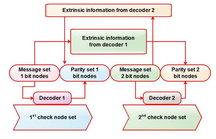
Chaitra et al. / Indian Journal of Science and Technology 2021;14(5):432–444

in LDPC codes increases with block length and for longer block length it will become relatively high. On the other hand, the
decoder of fully parallel LDPC is suffering from the complexity in implementation of the longer block length. The insensitive
application may limit the use of LDPC codes. Therefore, LDPC codes with the parallel concatenation of different methods were
introduced for longer codes to get better performance. Also, parallel concatenation reduces the encoding complexity for long
LDPC codes.
   Code concatenation of binary irregular LDPC codes is studded before (3–5) . Original parallel concatenated LDPC codes,
called Parallel Concatenated Gallager Codes (PCGCs), were proposed in (5) in which they showed how different component
codes with different parameters affect the overall performance in a Gaussian Channel. They restricted their description of
PCGC to rate 1/3 codes constructed by combining two rates 1/2 binary irregular LDPC codes without an interleaver.
   The authors in (6) showed that the interleaver is not needed for their proposed code. Also, they predicted that the conclusions
are easily extended to the case where three or more codes are used, as introduced in (7) in which a serial concatenated irregular
LDPC codes, without interleaver, is introduced. In (8) a PCGC was modified to use an interleaver. The interleaver swaps the
element positions of the code; i.e.it changes the weight distribution of the code. Thus, it helps increase the minimum distance
of the code. Also, the authors in (9) showed that high performance could be obtained, while fewer requirements of iterations,
with a serial concatenated of two binary irregular LDPC codes, with an interleaver. In (8) non-binary LDPC codes were applied
in a serial concatenation scheme with an interleaver. The authors in (9) showed that the proposed code scheme outperforms a
single nonbinary LDPC code. A serial concatenation of nonbinary LDPC codes is proposed in (9) . In this paper, we present the
different methods of LDPC codes with parallel concatenation.
   The rest of this paper is organized as follows: Overview about Parallel Concatenated Gallager Codes (PCGC) is presented
in section II, followed by PCGC structured as presented in section III. PCGC with the sets of two source bits, is presented
in section IV. Single encoder PCGC is presented in section VI. The modified PCGC is presented in section IV. PCGC with
interleaver is presented in section VII. At last conclusion is presented in section VIII.

2 Conventional PCGC
The Parallel Concatenated Gallager Codes (PCGC) is the class of concatenated codes (4) (5) . It allows to concatenate the two
LDPC encoders in parallel without using an interleaver between them. The PCGC conventional with concatenated codeword
and encoder structure is shown in Figure 1. The idea behind the development of PCGCs was to include the principle of turbo-
encoding in LDPC codes. In the long LDPC code, the complexity in decoding and encoding is divided into lower complexity
steps of decoding and encoding. Also, at the same time maintain the flow of information between decoder components and
reduces the information loss during the decoding steps. The component codes are selected based on the Mean Column Weight
(MCW) of the code’s parity-check matrix. MCW is the average column weight over all columns in the parity check matrix. It
has been found that by choosing low MCW code as the first component code and high MCW code as the second component
code, performance is improved. Figure 2 shows the effect of MCW on the extrinsic information in PCGC conventional encoder
for the various signal-to-noise range.

                             Fig 1. PCGC conventional encoder and structure of concatenated codeword

https://www.indjst.org/                                                                                                      433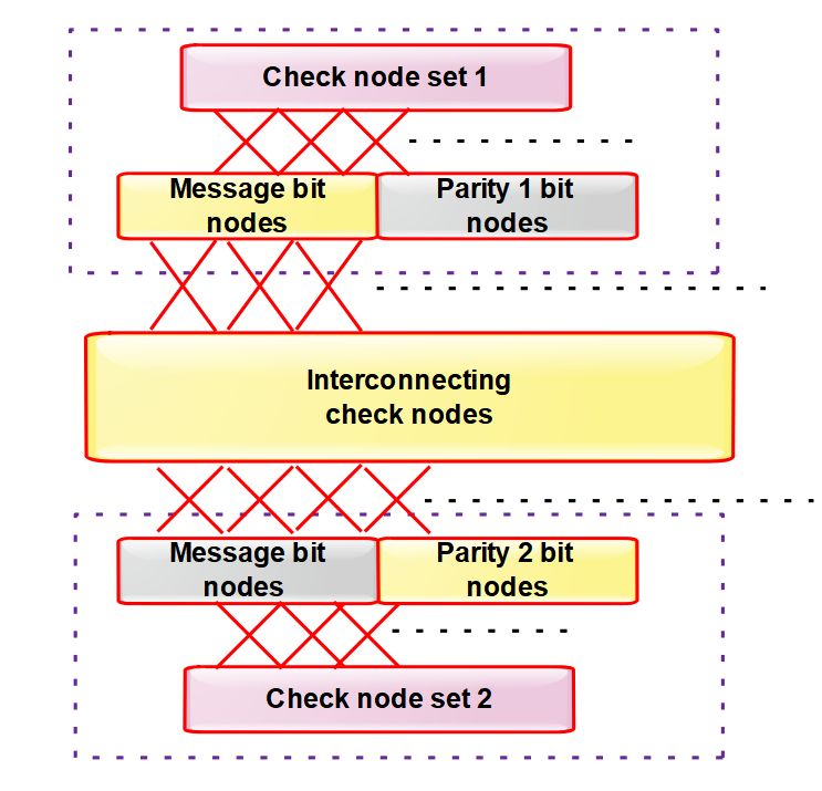
Chaitra et al. / Indian Journal of Science and Technology 2021;14(5):432–444

                          Fig 2. Effect of MCW on the extrinsic information SNR in PCGC conventional encoder

   The PCGCs decoding procedure is very similar to the turbo code decoding and no interleave between decoder components.
The Conventional PCGC decoder is shown in Figure 3. A posteriori probability is computed by each component of LPDC
decoder during the process of decoding as per (6) using a modified sum-product algorithm (3) . LDPC codes decoding is

https://www.indjst.org/                                                                                             434
Chaitra et al. / Indian Journal of Science and Technology 2021;14(5):432–444

an iterative process and this process will exchange the information between the decoder components. The LPDC decoder
component performs the algorithm of the sum-product in one complete cycle, which is referred to as local iteration. Any
information passing between decoder components, the local iterations must be performed by decoder components, and this
process called super iteration. The information exchange process between decoder components remains to continue till valid
codeword converges by both decoders. In the latter case, the output from the second component decoder is declared as the best
estimate of the transmitted sequence.

                                                 Fig 3. PCGC conventional decoder

   In conventional PCGC procedure, there are some limitations are reported. In each decoder component after performing a
fixed number of local iterations, the reliability i.e. log-likelihood ratio magnitudes of the systematic message bits are increased,
so it becomes difficult for the next component decoder to correct a maximum number of errors. Hence, coding gain provided
by concatenation of codes cannot be achieved. Further, local iterations perform by one decoder component, at the same time
other decoder component remains idle. After the fixed numbers of local iterations, information exchange may take place.
Therefore, in conventional PCGC delay in the decoding process is more. An “extensive computer search” was required to
select the component codes with different MCWs. As such, the efficacy of the scheme depends mainly on the complementary
behaviors of the individual LDPC codes.

2.1 Multiple PCGC
The generalization of PCGCs codes are from the Multiple Parallel Concatenated Gallager Codes [MPCGC] (7) . The encoder for
MPCGC is shown in Figure 4. Multiple LDPC encoders are connected in parallel in the structure of MPCGC instead of only
two encoder components in conventional PCGC. The LPDC component parity check matrices are constructed based on the
MCW and also make sure that in parity check matrices weights of the row must be uniform. In order to reduce the complexity
of MPCGC decoding and encoding, divide the long LPDC code into small subcodes, without compromising in performance.
The encoding complexity of conventional LDPC code is quadratic to the block length which is comparatively higher than the
sum of the complexities of the individual shorter component codes making up the MPCGC.

https://www.indjst.org/                                                                                                        435
Chaitra et al. / Indian Journal of Science and Technology 2021;14(5):432–444

                                                  Fig 4. Multiple PCGC encoders

   In terms of code parameters, the architecture of MPCGC has got flexibility in the greater potential to achieve the different
code rates using different subsets of component codes. In order to adapt to different channel conditions, it is also possible to
switch to different decoder configurations. This makes the architecture a desirable one for various applications.
   It is observed that, with low MCWs, LDPC codes outperform, and with high MCWs at low to moderate SNR, while they
exhibit low-grade performance at high SNR. (8) . Based on this statement MPCGC is designed to combine the codes of MCW
LPDC with low strength to a region of moderate SNR. The good design of MPCGC depends mainly on the choosing component
codes in design parameters. An “extensive computer search” option was used to obtain relatively higher, moderate, and low
LDPC codes.

                                     Fig 5. Effect of Bit error rate with respect to the code rate

https://www.indjst.org/                                                                                                     436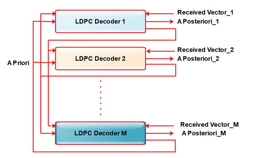
Chaitra et al. / Indian Journal of Science and Technology 2021;14(5):432–444

   Figure 5 shows the effect of MCW on the extrinsic information in PCGC conventional encoder for the various signal-to-noise
range.

                                                Fig 6. Serial Decoder of MPCGC

    The serial decoder structure of the MPCGC is shown in Figure 6. The process of decoding in the serial decoder of MPCGC
is similar to conventional PCGC, except that serial combinations of M component decoder are used. This serial process
will lead to more delay in producing the required results. Therefore, parallel decoding process is presented in (9) and the
corresponding structure of the MPCGC parallel decoder is shown in Figure 7. The decoding delay in the parallel decoding
process is significantly reduced by performing an operation in parallel by all M decoders. From the analysis, it was found that
at low SNR it is beneficial to increase the number of local iterations and decrease the number of super iterations. While at
moderate to high SNR, a few local iterations and more super iterations are recommended (10) .

                                             Fig 7. The parallel decoder of MPCGC

https://www.indjst.org/                                                                                                    437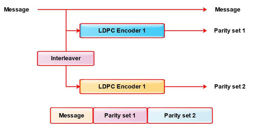
Chaitra et al. / Indian Journal of Science and Technology 2021;14(5):432–444

   The main drawback of the parallel decoding process was that combination of high, medium, and low MCW LDPC were
essential as component codes. Therefore, this scheme’s efficiency is rested with the individual LDPC codes complementary
behavior.

3 PCGC structure
The study shows that excellent bit-error rate (BER) performance can be obtained for large block lengths with the randomly
constructed LPDC codes. But in hardware implementation, the memory required for non-zero elements representation for
random matrix becomes more challenging. For the purpose of encoding and decoding the structured LDPC codes provides
simpler implementations. The effectiveness of the decoding algorithms for LPDC codes is characterized by the parameter called
Girth and it regulates the number of independent iterations. In the Tanner graph, the shortest cycle length is the parity check
matrix or Girth of the LDPC code. The performance of the LDPC decoders degrades in the Tanner graph due to the short cycle
having low girth because iterative decoding affects the exchange of extrinsic information (11) . Hence, LDPC code design with a
large girth is of great interest. The construction methods of structured LDPC, the main objective is to maintain girth as high as
possible in design LDPC codes. Based on Graphical models and Cayley graphs, the performance of half-rate, two structured,
and parallel concatenated LDPC codes are evaluated (12) . The performance is obtained through well-structured procedures of
two concatenated LDPC codes and compared with the same length of two randomly created LDPC components of conventional
PCGC.
    This method is less attractive for long block lengths because, as the length of the individual codes increases the SNR value at
which they will be outperformed by the parallel concatenated code is increased. Therefore, it can be concluded that this method
is a very good option only for short block lengths and high SNR values. Also, it could replace a single LDPC code of the same
length.

4 Two sets of source bits of PCGC
The two sets of source bits structure gas got better performance compared to conventional PCGC because it depends on the
architecture of concatenation (13) . The code selection of distinct components is not required for this method and used two
different parity check matrices (14–16) . The data interleaving between decoders component needs to be ensured, because of
using parity check matrices of two different. At the side of the transmission, this structure has two copies of the source message
bits, therefore, channel information is needed not be removed from the posterior metrics. Also, during extrinsic information
computing, this information was shared between the two decoder components and prior information was removed. The two
copies of source message bits are transmitted because one decoder component received information is different, hence source
bit information received independently by the other decoder component.
    First, at the transmitting side duplicate the message bits and then different generator matrices are used to encode the set
message bits to develop the set of two codewords, which are then concatenated. The structure of the concatenated codeword at
the transmitting side is shown in Figure 8. The resulting code is modulated further using binary phase-shift keying (BPSK) and
is then sent through the additive white Gaussian noise (AWGN) channel.

                             Fig 8. Structure of PCGC concatenated code word with two sets of source bits

   The PCGC decoder architecture with source bits of two sets is shown in Figure 9. At the side of the receiving link, the
received packet of the first set is assigned to the first decoder, and vectors of the second set are assigned to the second decoder.

https://www.indjst.org/                                                                                                        438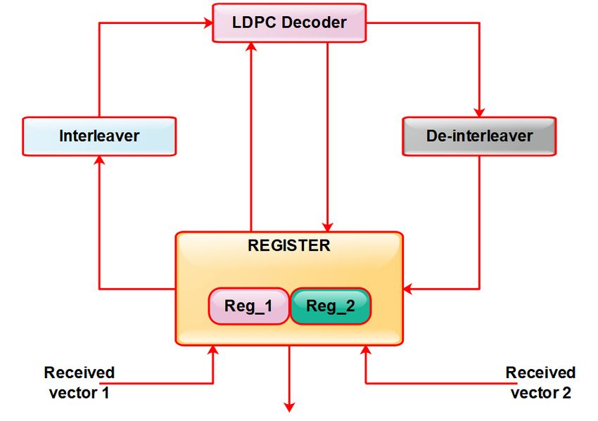
Chaitra et al. / Indian Journal of Science and Technology 2021;14(5):432–444

The extrinsic information is shared between the systematic message bits of the two-component decoders.

                                   Fig 9. PCGC architecture of decoder with source bits of two sets

5 Single encoder PCGC
Only a single component LDPC code with MCW >2.5 is used in a single encoder PCGC (17) . The message bits corresponding
same parity bits are transmitted twice. A single encoder PCGC structure with concatenated codeword and encoder is shown
in Figure 10. In this structure complexity of encoding is significantly reduced and is less compared to the other parallel
concatenation techniques.

                          Fig 10. A single encoder PCGC structure with concatenated codeword and encoder

https://www.indjst.org/                                                                                               439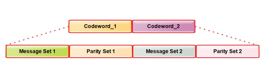
Chaitra et al. / Indian Journal of Science and Technology 2021;14(5):432–444

   The decoder for PCGC with a single encoder is shown in Figure 11. At the side of the decoding two-component decoders
are connected in parallel by using check nodes called the interconnecting check node. Each interconnecting check node
corresponds to one parity-check equation of the corresponding parity-check matrix and an edge joins an interconnecting check
node and a bit node of each component decoder if that particular bit is involved in the corresponding parity-check equation. In
the first step of the super iteration, both component decoders will independently and simultaneously perform one local iteration
of the iterative decoding i.e. the intrinsic information from bit nodes are transferred to the check nodes of the corresponding
decoder, and bit nodes are updated based on the extrinsic message available from the check nodes.

                                            Fig 11. PCGC decoder with a single encoder

   Further, in the next step decoder component, each bit is updated first (i.e. modified value likelihood ratio) by using intrinsic
information of the second decoder component. Similarly, in the second decoder component, each bit is updated by using
intrinsic information of the first decoder component. Until one of the decoders converges to a valid codeword this process

https://www.indjst.org/                                                                                                       440
Chaitra et al. / Indian Journal of Science and Technology 2021;14(5):432–444

will continue or a maximum number of super iterations are over.

6 Modified PCGC
In the modified PCGC structure, two different sets of parity bits are transmitted for the same information block (18–21) . The zero
syndrome criteria satisfy by parity bits of one set and non-zero syndrome criteria satisfy another set of parity bits. At the starting
of the message block a ‘1’ is added to generate the non-zero syndrome parity set from the second decoder. The performance
can be slightly increased compared to PCGC with a single encoder, due to the increase in minimum distance for the carefully
chosen syndrome vector, without any change in the complexity of the decoder.
   The modified PCGC structure with concatenated codeword and encoder is shown in Figure 12.
   Encoder for modified PCGC consists of a pair of simple LDPC encoders, one for obtaining code word that satisfies zero
syndrome criteria and the other for obtaining code word that satisfies non-zero syndrome criteria.

                              Fig 12. Modified PCGC structure with concatenated codeword and encoder.

    For decoding, message-passing algorithm needed slight modifications to accommodate the non-zero syndrome criteria. Bit
flipping algorithm is used for decoding. In the first step of the super iteration, the decoder will perform a local iteration with
code word satisfying zero syndrome criteria. In the second step, the decoder will perform a local iteration with code word
satisfying non-zero syndrome criteria. In the third step, intrinsic information is updated using the extrinsic information that
each bit node received from the check nodes. Bit nodes corresponding to parity bits and systematic message bits are updated
separately. This process of super iteration continues until one of the decoders converges to a valid codeword or a maximum
number of super iterations are over.
    The structure of the modified PCGC also has some limitations. The extrinsic messages received by each bit node during
a super iteration are not fully independent and are correlated, which worsens the performance of the iterative decoding. It is
because if there is a bit in error, then there is a possibility that the messages received by the bit nodes from the check nodes
will be contradictory. So as to have improved performance, all the information received by a bit node has to be independent.
Other demerits include its applicability only in Binary Symmetric Channel (BSC) and random selection of non-zero syndrome
vector (22) .

https://www.indjst.org/                                                                                                          441
Chaitra et al. / Indian Journal of Science and Technology 2021;14(5):432–444
7 PCGC with Interleaver
An interleaver is used, to make PCGC to be independent, when nodes received the extrinsic messages bit by bit. In PCGC
with interleaver, nodes will receive the messages independently, because the parity equations will become entirely different by
using an interleaver and this will make to improve the performance (23–26) . An interleaver PCGC structure with concatenated
codeword and encoder is shown in Figure 13. In this interleaver structure message bits of parity, sets are provided by the first
encoder, and message bits for interleaved parity set are provided by the second encoder. Here syndrome criteria are satisfied
by both parity bits. The message bits randomly permutes by using a random interleaver. Because of the use of interleaver, the
complexity of the structure is increased and this becomes the main drawback of this structure.
Fig 13. Interleaver PCGC structure with concatenated codeword and encoder
The decoder for PCGC with interleaver is shown in Figure 14. A simple LDPC decoder is used to decode both the codeword.
It also consists of a register block, a random interleaver, and a de- interleaver.
In the structure of decoder for PCGC with interleaver contains two registers set Reg1 and Reg 2 to store code word. Also, total
extrinsic information and intrinsic information is stored in these registers of a corresponding codeword of each bit. Decoder
outputs the total extrinsic message for each bit after a local iteration. Decoder is connected directly as well as through interleaver
and de-interleaver to register block. De-interleaver does the reverse operation of interleaver. Complexity and decoding delay
will be more compared with other techniques due to the presence of interleaver and de-interleaver. Decoding delay can be
reduced by using parallel set of decoders.
The algorithm called Bit flipping is used for the purpose of decoding. In the super iteration first step decoder performs a local
iteration with the first codeword and the total extrinsic information is sent back to the Reg1 of the register block. The intrinsic
information of message bits and parity bits are taken directly to decoder and total extrinsic information of the message bits and
parity bits are transferred directly to the Reg1. In the second step of the super iteration, decoder performs a local iteration with
permuted codeword and the total extrinsic information is sent back to the Reg2 of the register. Here the intrinsic information of
message bits is taken to decoder through interleaver and that of parity bits are taken directly. While the total extrinsic message
corresponding to parity bits is sent back through the direct path and the total extrinsic message corresponding to message bits
is sent back through the de-interleaver. In the third step of the super iteration, intrinsic information in the register block (Reg1
and Reg2) is updated using the total extrinsic information received from the decoder. But the parity bits and the systematic
message bits are updated separately. This process of super iteration continues until one of the decoder converges to a valid
codeword or a maximum number of super iterations are over.
The performance of PCGC with interleaver is compared with modified PCGC in BSC (27–30) and results show PCGC with
interleaver has better performance. In an AWGN channel, the performance of PCGC with interleaver is increased by a factor,
which is the indirect increase of column-weight. This is because there is an indirect increase in the number of check nodes
connected to each bit node without changing the number of bit nodes connected to each check node. Hence, this scheme of
https://www.indjst.org/ 442Chaitra et al. / Indian Journal of Science and Technology 2021;14(5):432–444
Fig 14. Decoder for PCGC with interleaver
concatenation provides the better performance as good a dedicated LDPC but with increased complexity due to deployment of
an interleaver. The implementation problem associated with a longer block length iterative decoder is solved with PCGC with
interleaver without much compromise in the performance.
8 Conclusion
The parallel concatenation of multiple LDPC codes is evaluated based on different decoding techniques. By breaking a
long, high-complexity single LDPC code into multiple lower-complexity LDPC codes and appropriately exchanging extrinsic
information among the component decoders, it is shown that a competitive BER performance can be achieved while still
maintaining the low complexity and flexibility attributes of these strategies. By optimizing the construction of the component
LDPC codes, the performance of MPCGC can be significantly improved and the complexity can be further reduced. MPCGC
strategies can be attractive in applications where an on-line trade-off of resource vs coding performance is required; these are
also advocated for the emerging multicore processing platform.
This study provides complete fundamental details of the design and implementation of LDPC codes by considering forward
error corrections, error floor, and higher code rate for performance analysis. In recent years, the Low Density Parity Check
(LDPC) code has found remarkable advancement and has seen them outshine turbo codes in terms of performance especially
in the error floor and higher code rate. The performance and other inherent advantages make the LDPC codes the best choice
for error-correction. However, complexity in the implementation of longer block length code is the main shortcoming of this
code. In many practical applications, the LDPC codes outperform the turbo codes, therefore over turbo codes, the LPDC codes
are not preferred because of this drawback. In terms of performance, parallel concatenation with interleaver structure is a good
choice than the existing structure. However, the presence of interleaver makes this structure more complex.
Acknowledgement
The authors acknowledge with thanks Vision Group of Science & Technology (VGST ), Karnataka Fund for Infrastructure
Strengthening in Science & Technology (K-FIST).
https://www.indjst.org/ 443Chaitra et al. / Indian Journal of Science and Technology 2021;14(5):432–444
References
1) Branco P, Mateus P, Salema C, Souto A. Using Low-Density Parity-Check codes to improve the McEliece cryptosystem. Information Sciences. 2020;510:243–
255. Available from: https://dx.doi.org/10.1016/j.ins.2019.09.030.
2) Pramanik A, Maity SP, Sarkar S. Compressed sensing image reconstruction by low density parity check codes and soft decoding of space time block codes.
Computers & Electrical Engineering. 2018;72:553–565. Available from: https://dx.doi.org/10.1016/j.compeleceng.2018.01.014.
3) Shrinidhia J, Krishnaa PS. Modified Min Sum Decoding Algorithm for Low Density Parity Check Codes. Third International Conference on Computing
and Network Communications (CoCoNet’19). 2020;p. 2128–2136. Available from: https://doi.org/10.1016/j.procs.2020.04.230.
4) Aswathy GP, Gopakumar K, Ahamed TPI. Parallel concatenated Gallager codes for reliable data transmission in cognitive radio networks. Physical
Communication. 2019;37. Available from: https://dx.doi.org/10.1016/j.phycom.2019.100831.
5) Oudjani B, Tebbikh H, Doghmane N. Modification of extrinsic information for parallel concatenated Gallager/Convolutional code to improve
performance/complexity trade-offs. AEU - International Journal of Electronics and Communications. 2018;83:484–491. Available from: https://dx.doi.
org/10.1016/j.aeue.2017.10.033.
6) Behairy H, Chang SC. Analysis and design of parallel concatenated Gallager codes. Electronics Letters. 2002;38(18). Available from: https://dx.doi.org/
10.1049/el:20020719.
7) Aftan A, Benaissa M. Efficient coding Method of Multiple Parallel Concatenated Gallager Codes for WiMAX. IEEE publisher. 2018;23:1–6. Available
from: https://doi.org/10.1109/WIAD.2018.8588450.
8) Behairy HM, Benaissa M. Multiple parallel concatenated gallager codes: Code design and decoding techniques. IETE Journal of Research. 2013;59(6):659–
659. Available from: https://dx.doi.org/10.4103/0377-2063.126948.
9) Aswathy GP, Gopakumar K. Performance Comparison of Parallel Concatenated Gallager Codes with Different Types of Interleavers. International CET
Conference on Control, Communication, and Computing (IC4). 2018;p. 210–216. Available from: https://doi.org/10.1109/CETIC4.2018.8531011.
10) Mostari L, Taleb-Ahmed A. Serial Concatenation of Binary LDPC Codes with Iterative Decoding. International Journal of Recent Engineering Science
(IJRES);6(6):7–10.
11) Rankin DM, Gulliver TA, Taylor DP. Parallel and Serial Concatenated Single Parity Check Product Codes. EURASIP Journal on Advances in Signal
Processing. 2005;2005(6):775–783. Available from: https://dx.doi.org/10.1155/asp.2005.775.
12) Alfiras M, Hadi AHW. Parallel Concatenation of LDPC Codes with LTE Modulation Schemes. Applied Mathematics & Information Sciences An
International Journal. 2018;6:1165–1176. Available from: http://dx.doi.org/10.18576/amis/120611.
13) Liu S, Song A. Optimization of LDPC Codes over the Underwater Acoustic Channel. International Journal of Distributed Sensor Networks. 2016;12(2).
Available from: https://dx.doi.org/10.1155/2016/8906985.
14) Paolini E, Flanagan M. Low-Density Parity-Check Code Constructions. Channel Coding: Theory, Algorithms, and Applications. 2014;p. 141–209. Available
from: http://dx.doi.org/10.1016/B978-0-12-396499-1.00003-0.
15) Shivaji R, Nataraj KR. Design and implementation of reconfigurable DCT based adaptive PST techniques in OFDM communication system using
interleaver encoder. Journal of Science and Technology;2020(29):3008–3020. Available from: https://doi.org/:10.17485/IJST/v13i29.976.
16) Madhu TA, Komala M. Design of fuzzy logic controlled hybrid model for the control of voltage and frequency in microgrid. Journal of Science and
Technology. 2020;13(35):3612–3629. Available from: https://doi.org/10.17485/IJST/v13i35.1510.
17) Mallikarjunaswamy S, Sharmila N. Implementation of an effective hybrid model for islanded microgrid energy management. Indian Journal of Science
and Technology. 2020;13(27):2733–2746. Available from: https://dx.doi.org/10.17485/ijst/v13i27.982.
18) Raj KS, Siddesh GK. Interference resilient stochastic prediction based dynamic resource allocation model for cognitive MANETs”. Journal of Science and
Technology. 2020;13(41):4332–4350. Available from: https://doi.org/10.17485/IJST/v13i41.687.
19) Zhe Z, Fei G, Hao Z, Xue Y. Area-efficient analog decoder design for low density parity check codes in deep-space applications. The Journal of China
Universities of Posts and Telecommunications. 2017;24(4):69–75. Available from: https://dx.doi.org/10.1016/s1005-8885(17)60225-5.
20) Vijayalakshmi S, Nagarajan V. Energy efficient low density parity check scheme for body channel communication using FPGA. Microprocessors and
Microsystems. 2019;68:84–91. Available from: https://dx.doi.org/10.1016/j.micpro.2019.04.005.
21) Maier AJ, Cockburn BF. Optimization of Low-Density Parity Check decoder performance for OpenCL designs synthesized to FPGAs. Journal of Parallel
and Distributed Computing. 2017;107:134–145. Available from: https://dx.doi.org/10.1016/j.jpdc.2017.04.001.
22) Liu H, Ma L, Chen J. Multistep linear programming approaches for decoding low-density parity-check codes. Tsinghua Science and Technology.
2009;14(5):556–560. Available from: https://dx.doi.org/10.1016/s1007-0214(09)70117-8.
23) Umashankar ML, Mallikarjunaswamy S, Ramakrishna MV. Design of High Speed Reconfigurable Distributed Life Time Efficient Routing Algorithm in
Wireless Sensor Network. Journal of Computational and Theoretical Nanoscience. 2020;17(9):3860–3866. Available from: https://dx.doi.org/10.1166/jctn.
2020.8975.
24) Umashankar ML, Ramakrishna MV. Design of High Speed Reconfigurable Deployment Intelligent Genetic Algorithm in Maximum Coverage Wireless
Sensor Network. 2019 International Conference on Data Science and Communication (IconDSC). 2019;p. 1–6. Available from: https://doi.org/10.1109/
IconDSC.2019.8816930.
25) Satish P, Srikantaswamy M, Ramaswamy N. A Comprehensive Review of Blind Deconvolution Techniques for Image Deblurring. Traitement du Signal.
2020;37(3):527–539. Available from: https://dx.doi.org/10.18280/ts.370321.
26) Yang Y, Jian-Zhong H. Replica horizontal-shuffled iterative decoding of low-density parity-check codes. The Journal of China Universities of Posts and
Telecommunications. 2010;17(6):32–40. Available from: http://dx.doi.org/10.1016/S1005-8885(09)60522-7.
27) Hao Z, Shuyi Z, Lintao L, Yuan G, Liwei S. Probability stopping criterion for analog decoding of LDPC codes. The Journal of China Universities of Posts
and Telecommunications. 2017;24:35–39. Available from: https://dx.doi.org/10.1016/s1005-8885(17)60185-7.
28) Mahendra HN, Shivakumar BR, Praveen J. Pixel-based Classification of Multispectral Remotely Sensed Data Using Support Vector Machine Classifier”.
International Journal Of Innovative Research In Electrical, Electronics, Instrumentation And Control Engineering. 2015;3:94–98. Available from: http:
//dx.doi.org/10.17148/IJIREEICE.
29) Mahendra HN, Mallikarjunaswamy S, Rekha V, Puspalatha V, Sharmila N. Performance Analysis of Different Classifier for Remote Sensing Application.
International Journal of Engineering and Advanced Technology. 2019;9:7153–7158. Available from: http://dx.doi.org/10.35940/ijeat.A1879.109119.
30) Mahendra HN, Mallikarjunaswamy S, Siddesh GK, Komala M, Sharmila N. Evolution of real-time onboard processing and classification of remotely
sensed data. Indian Journal of Science and Technology. 2020;13. Available from: https://doi.org/10.17485/IJST/v13i20.459.
https://www.indjst.org/ 444You can also read