MODBUS RTU Network Adapter Light - RIO3-MBRL
←
→
Page content transcription
If your browser does not render page correctly, please read the page content below
1                            HX-RIO3 Series

    MODBUS RTU Network Adapter Light

                          RIO3-MBRL
                         User manual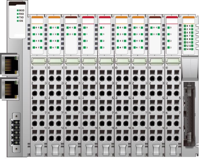
2                                                  HX-RIO3 Series

                      DOCUMENT CHANGE SUMMARY
REV       PAGE               REMARKS             DATE      EDITOR
1.00   New Document                             Feb 2021    Faber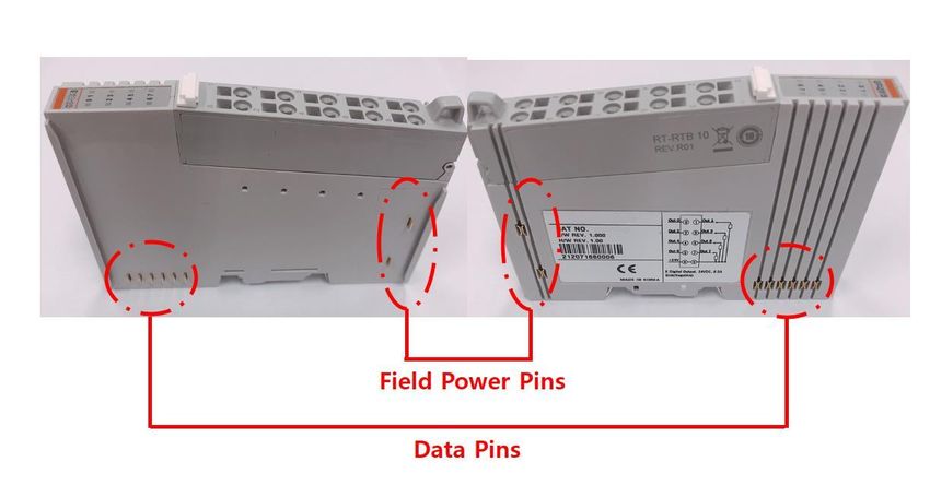
3                                                                                                                      HX-RIO3 Series

Contents

1. Important Note .......................................................................................................................... 5
1.1. Safety Instruction ................................................................................................................... 6
1.1.1. Symbols ............................................................................................................................... 6
1.1.2. Safety Notes ........................................................................................................................ 6
1.1.3. Certification ......................................................................................................................... 6
2. Specification.............................................................................................................................. 7
2.1. Interface .................................................................................................................................. 7
2.1.1. RIO3-MBRL .......................................................................................................................... 7
2.2. Specification........................................................................................................................... 8
2.2.1. General Specification.......................................................................................................... 8
2.2.2. Interface Specification ........................................................................................................ 9
2.3. LED Indicator........................................................................................................................ 10
2.3.1 MOD (Module Status LED) ................................................................................................. 10
2.3.2 RXD (Receive Data LED) .................................................................................................... 10
2.3.3 TXD (Transmit Data LED)................................................................................................... 10
2.3.4 IOS LED (Extension Module Status LED) ......................................................................... 10
3. Dimension ............................................................................................................................... 11
3.1. RIO3-MBRL ........................................................................................................................... 11
4. Mechanical Set Up .................................................................................................................. 12
4.1. Total Expansion ................................................................................................................... 12
4.2. Plugging and Removal of the Components ....................................................................... 12
5. MODBUS Electrical Interface ................................................................................................. 12
5.1. G-Bus System ...................................................................................................................... 14
5.3. RIO3-MBRL Electrical Interface........................................................................................... 16
5.3.1. RJ-45 Socket ..................................................................................................................... 16
5.3.2. MODBUS Dip Switch Setup .............................................................................................. 16
5.3.3. Process Image Map ........................................................................................................... 17
5.3.4. MODBUS Interface Register/Bit Map ............................................................................... 17
5.4. Example ................................................................................................................................ 18
5.4.1. Example of Input Process Image (Input Register) Map .................................................. 18
5.4.2. Example of Output Process Image (Output Register) Map ............................................ 19
6. MODBUS TCP/UDP INTERFACE ............................................................................................ 20
6.1 MODBUS TCP/ UDP Protocol ............................................................................................... 20
4                                                                                                                   HX-RIO3 Series

6.1.1. Comparison of MODBUS TCP/UDP and MODBUS/RTU ................................................. 20
6.1.2. MODBUS TCP/ UDP MBAP Header .................................................................................. 21
6.2 Supported MODBUS Function Codes.................................................................................. 21
6.2.1. 1(0x01) Read Coils ............................................................................................................ 22
6.2.2. 2(0x02) Read Discrete Inputs ........................................................................................... 22
6.2.3. 3(0x03) Read Holding Registers....................................................................................... 23
6.2.4. 4 (0x04) Read Input Registers .......................................................................................... 23
6.2.5. 5 (0x05) Write Single Coil ................................................................................................. 24
6.2.6. 6 (0x06) Write Single Register .......................................................................................... 25
6.2.7. 8 (0x08) Diagnostics ......................................................................................................... 25
6.2.8. 15 (0x0F) Write Multiple Coils........................................................................................... 27
6.2.9. 16 (0x10) Read/Write Multiple Registers .......................................................................... 28
6.2.10. 23 (0x17) Read/Write Multiple Registers ........................................................................ 29
6.2.11 Error Response ................................................................................................................ 29
6.3 MODBUS Special Register Map ........................................................................................... 30
6.3.1 Adapter Identification Special Register (0x1000, 4096) ................................................... 30
6.3.2 Adapter Watchdog Time, other Time Special Register (0x1020, 4128) ........................... 31
6.3.3 Adapter Information Special Register (0x1100, 4352)...................................................... 31
6.3.4 Expansion Slot Information Special Resister (0x2000, 8192) .......................................... 33
6.4. MODBUS Reference ............................................................................................................. 34
7. Troubleshooting...................................................................................................................... 35
How to diagnose by LED indicator ............................................................................................ 35
How to diagnose when device couldn't communicate network .............................................. 36
A.1 Product List .......................................................................................................................... 37
A.2. Glossary ............................................................................................................................... 38
5                                                                                           HX-RIO3 Series

1. Important Note
Solid state equipment has operational characteristics differing from those of electromechanical equipment.
Safety Guidelines for the Application, Installation and Maintenance of Solid-State Controls describes some
important differences between solid state equipment and hard-wired electromechanical devices.
Because of this difference, and also because of the wide variety of uses for solid state equipment, all persons
responsible for applying this equipment must satisfy themselves that each intended application of this
equipment is acceptable.
In no event will HITACHI be responsible or liable for indirect or consequential damages resulting from the use
or application of this equipment.
The examples and diagrams in this manual are included solely for illustrative purposes. Because of the many
variables and requirements associated with any installation, HITACHI cannot assume responsibility or liability
for actual use based on the examples and diagrams.

    Warning!

✓    If you don't follow the directions, it could cause a personal injury, damage to the equipment or
     explosion
⚫        Do not assemble the products and wire with power applied to the system. Else it may cause an
electric arc, which can result into unexpected and potentially dangerous action by field devices. Arching is
explosion risk in hazardous locations. Be sure that the area is non-hazardous or remove system power
appropriately before assembling or wiring the modules.
⚫       Do not touch any terminal blocks or IO modules when system is running. Else it may cause the unit to
an electric shock or malfunction.
⚫        Keep away from the strange metallic materials not related to the unit and wiring works should be
controlled by the electric expert engineer. Else it may cause the unit to a fire, electric shock or malfunction.

    Caution!

✓    If you disobey the instructions, there may be possibility of personal injury, damage to equipment
     or explosion. Please follow below Instructions.
⚫      Check the rated voltage and terminal array before wiring. Avoid the circumstances over 55℃ of
temperature. Avoid placing it directly in the sunlight.
⚫        Avoid the place under circumstances over 85% of humidity.
⚫        Do not place Modules near by the inflammable material. Else it may cause a fire.
⚫        Do not permit any vibration approaching it directly.
⚫        Go through module specification carefully, ensure inputs, output connections are made with the
specifications. Use standard cables for wiring.
⚫        Use Product under pollution degree 2 environment.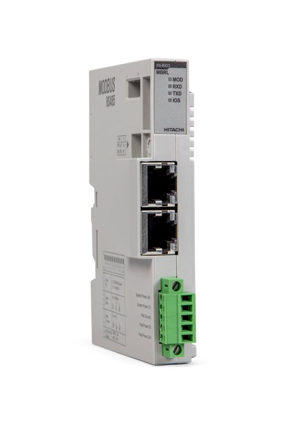
6                                                                                   HX-RIO3 Series

1.1. Safety Instruction
1.1.1. Symbols

                    Information about practices or circumstances that can cause an explosion in a
                  hazardous environment, which may lead to personal injury or death property
                  damage, or economic loss.

                  Identifies information that is critical for successful application and understanding of
                  the Product.

                 Identifies information about practices or circumstances that can lead to personal
                 Injury, property damage, or economic loss.
                 Attentions help you to identity a hazard, avoid a hazard, and recognize the
                 consequences.

1.1.2. Safety Notes

                 The modules are equipped with electronic components that may be destroyed by
                 electrostatic discharge. When handling the modules, ensure that the environment
                 (persons, workplace and packing) is well grounded. Avoid touching conductive
                 components, e.g. G-BUS Pin.

1.1.3. Certification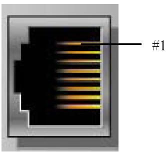
7                                                  HX-RIO3 Series

2. Specification
2.1. Interface
2.1.1. RIO3-MBRL

                   Pin No.    Signal Description
                      1      System Power, 24V
                      2      System Power, 24V
                      3               F.G
                      4      Field Power, Ground
                      5        Field Power, 24V
8 HX-RIO3 Series
2.2. Specification
2.2.1. General Specification
General specification
UL System Power Supply voltage: 24Vdc nominal, Class 2
Supply voltage: 24Vdc nominal
System Power Supply voltage range: 15~28.8Vdc
Reverse polarity protection
Power Dissipation 20mA typical @ 24Vdc
Current for I/O Module 1.0A @ 5Vdc
System power to internal logic: Non-isolation
Isolation
System power I/O driver: Isolation
UL Field Power Supply voltage: 24Vdc nominal, Class 2
Supply voltage: 24Vdc typical
Field Power * Field Power Range is different depending on IO Module series.
Refer to IO Module`s Specification.
Max. Current Field Power Contact DC 8A Max
Wiring I/O Cable Max. 2.0㎟(AWG14)
Torque 0.8Nm (7 lb-in)
Weight 77g
Module Size 22mm x 109mm x 70mm
Environmental specification
Operating Temperature - 20℃ ~ 60 ℃: 1.0A full load is allowed.
UL Temperature - 20℃ ~ 60 ℃
Storage Temperature - 40℃ ~ 85 ℃
Relative Humidity 5% ~ 90% non-condensing
Mounting DIN rail9 HX-RIO3 Series
2.2.2. Interface Specification
Interface Specification RIO3-MBRL (RS-485)
Adapter Type Slave node (MODBUS Serial RTU/ASCII Server)
Protocol MODBUS RTU and ASCII
Max. Expansion Module 16 slots
Max. Data Size (Input + Output) Max. Input 256 bytes / Output 256 bytes
Max Length Bus Line 500m
Max. Nodes 8 nodes
Baud Rate 2400, 4800, 9600, 19200, 38400, 57600, 115200 bps
Interface Connector RJ-45 socket * 2pcs
Settable Node Address Via Dip switch
Indicator 4 LEDs
1 Green/Red, Module Status (MOD)
1 Green, Physical Connection (LINK)
1 Green, Exchange Date/Traffic Present (ACTIVE)
1 Green/Red, Expansion I/O Module Status (IOS)
Module Location Starter module left side of RIO3 Series system
General specification
Shock Operating IEC 60068-2-27
Vibration Resistance Based on IEC 60068-2-6
Industrial Emissions EN 61000-6-4/A11 : 2011
Industrial Immunity EN 61000-6-2 : 2005
Installation Position Vertical and horizontal installation is available
Product Certifications CE, UL, EAC10 HX-RIO3 Series
2.3. LED Indicator
LED LED Function / Description LED Color
MOD Module Status Green/Red
RXD Physical Connection Green
TXD Exchange Data/Traffic Present Green
IOS Expansion Module Status Green/Red
2.3.1 MOD (Module Status LED)
Status LED To indicate
Not Powered OFF Power is not supplied to the unit.
Device Operational Green The unit is operating in normal condition.
The device has an unrecoverable fault.
Unrecoverable Fault Red
- Memory error or CPU watchdog error.
2.3.2 RXD (Receive Data LED)
Status LED To indicate
Not Powered or Not Linked OFF Device is idle or may not be powered.
Adapter received correct Adapter (Slave) received correct frame which address to the
Green
message frame slave or broadcast. About 20msec flashing
2.3.3 TXD (Transmit Data LED)
Status LED To indicate
Not Powered OFF Device is idle or may not be powered.
Adapter transmit frame Flashing Green Adapter (slave) transmit frame. About 20msec flashing.
2.3.4 IOS LED (Extension Module Status LED)
Status LED To indicate
Not Powered OFF Device may not be powered.
No Expansion Module Flashing Red Adapter has no expansion module
Internal Bus Connection,
Green Exchanging I/O data.
Run Exchanging I/O
One or more expansion module occurred in fault state.
- Detected invalid expansion module ID.
- Overflowed Input /Output Size
- Too many expansion module
Expansion Configuration
Red - Initialization failure
Failed
- Communication failure.
- Changed expansion module configuration.
- Mismatch vendor code between adapter and expansion
module.11 HX-RIO3 Series
3. Dimension
3.1. RIO3-MBRL
(mm)12 HX-RIO3 Series
4. Mechanical Set Up
4.1. Total Expansion
The number of the module assembly that can be connected is 16. So the maximum length is 214mm
Exception.
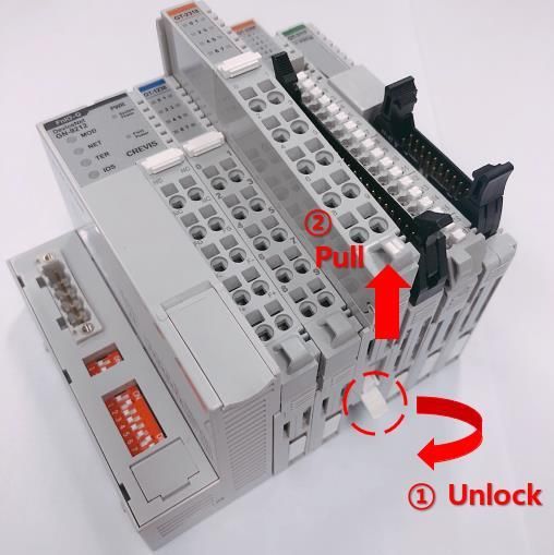
4.2. Plugging and Removal of the Components
As above figure in order to safeguard the RIO3 module from jamming, it should be fixed onto the DIN rail with
locking level. To do so, fold on the upper of the locking lever.
To pull out the RIO3 module, unfold the locking lever as below figure.
Before work is done on the components, the voltage supply must be turned off.13 HX-RIO3 Series
5. MODBUS Electrical Interface
Slot 1614 HX-RIO3 Series
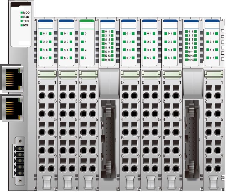
5.1. G-Bus System
• Network Adapter Module
The Network Adapter Module forms the link between the field bus and the field devices with the Expansion
Modules.
The connection to different field bus systems can be established by each of the corresponding Network
Adapter Module, e.g. for PROFIBUS, CAN open, Ethernet/IP, MODBUS/Serial, MODBUS/TCP etc.
• Expansion Module
The Expansion Modules are supported a variety of input and output field devices.
There are digital and analog input/output modules and special function modules.
• Two types of G-Bus Message
- Service Messaging
- I/O Messaging15 HX-RIO3 Series
5.2 G-Bus Pin Description
Communication between the RIO3 series and the expansion module as well as system / field power supply
of the bus modules is carried out via the internal bus. It is comprised of 6 data pin and 2 field power
ping
No. Name Description
1 Vcc System supply voltage (5V dc).
2 GND System Ground.
3 Token Output Token output port of Processor module.
4 Serial Output Transmitter output port of Processor module.
5 Serial Input Receiver input port of Processor module.
6 Reserved Reserved for bypass Token.
7 Field GND Field Ground.
8 Field Vcc Field supply voltage (24Vdc).
Do not touch data and field power pins in order to avoid soiling and damage by ESD
noise.16 HX-RIO3 Series
5.3. RIO3-MBRL Electrical Interface
5.3.1. RJ-45 Socket
RJ-45 Signal Name Description
1 RS485 + Transmit +
2 RS485 − Transmit −
3 GND Communication Ground
4 −
5 −
6 −
7 −
8 FG Frame Ground
Shield RJ-45 Socket Case Shield
5.3.2. MODBUS Dip Switch Setup
DIP Switch
Item Item setup
#1 #2 #3 #4 #5 #6 #7 #8 #9 #10
EEPROM value* OFF OFF OFF
Node ID Node ID 1 ON OFF OFF
Node ID 7 ON ON ON
115200bps OFF OFF OFF
2400 bps ON OFF OFF
4800 bps OFF ON OFF
9600 bps ON ON OFF
Baud rate
19200 bps OFF OFF ON
38400 bps ON OFF ON
57600 bps OFF ON ON
115200 bps ON ON ON
8bit, No Parity, 1Stop OFF OFF OFF
8bit, Even Parity, 1Stop ON OFF OFF
8bit, Odd Parity, 1Stop OFF ON OFF
Byte
8bit, No Parity, 2Stop ON ON OFF
Format
7bit, Even Parity, 1Stop** ON OFF ON
7bit, Odd Parity, 1Stop** OFF ON ON
8bit, No Parity, 1Stop ON ON ON
RTU/ASCI RTU Mode OFF
I Mode ASCII Mode ON
* Factory default value is 1.
** ASCII Mode is only available17 HX-RIO3 Series
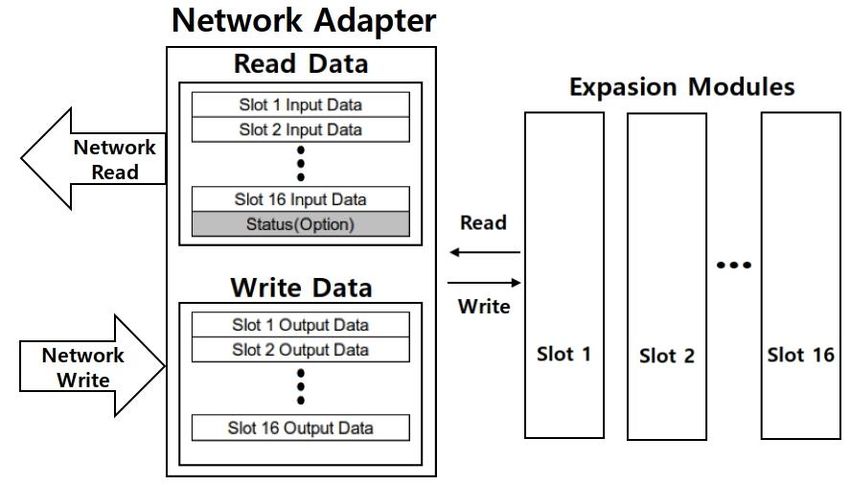
5.3.3. Process Image Map
An expansion module may have 3 types of data as I/O data, configuration parameter and memory register.
The data exchange between Network Adapter and expansion modules is done via an I/O process image data
by RIO3 Series protocol. The following figure shows the data flow of process image between Network Adapter
and expansion modules.
5.3.4. MODBUS Interface Register/Bit Map
• Register Map
Start Func. Code
Read/Write Description
Address
0x0000 ~ Read Process input image registers (Real Input Register) 3,4,23
0x0800 ~ Read/Write Process output image registers (Real Output Register) 3,16,23
0x1000 * Read Adapter Identification special registers. 3,4,23
0x1020 * Read/Write Adapter Watchdog, other time special register. 3,4,6,16,23
0x1100 * Read/Write Adapter Information special registers. 3,4,6,16,23
0x2000 * Read/Write Expansion Slot Information special registers. 3,4,6,16,23
* The special register map must be accessed by read/write of each address (one address).
• Register Map
Start Address Read/Write Description Func. Code
0x0000~ Read Process input image bits
All input registers area is addressable by bit address. 2
Size of input image bit is size of input image register * 16.
Process output image bits
All output registers area is addressable by bit address.
0x1000~ Read/Write 1,5,15
Size of output image bit is size of output image register *
16.18 HX-RIO3 Series
5.4. Example
5.4.1. Example of Input Process Image (Input Register) Map
Input image data depends on slot position and expansion slot data type. Input process image data is only
ordered by expansion slot position.
Example slot configuration
Slot Module Description
Address
#0 MODBUS RS485 Adapter
#1 8-discrete input
#2 8-discrete input
#3 4-analog input
#4 16-discrete input
#5 8-discrete input
#6 8-discrete input
#7 8-discrete input
#8 16-discrete input
#9 8-discrete input
Address B15 B14 B13 B12 B11 B10 B9 B8 B7 B6 B5 B4 B3 B2 B1 B0
0x0001 Discrete Input 8 pts (Slot#2) Discrete Input 8 pts (Slot#1)
0x0002 Analog Input Ch0 high byte (Slot#3) Analog Input Ch0 low byte (Slot#3)
0x0003 Analog Input Ch1 high byte (Slot#3) Analog Input Ch1 low byte (Slot#3)
0x0004 Analog Input Ch2 high byte (Slot#3) Analog Input Ch2 low byte (Slot#3)
0x0005 Analog Input Ch3 high byte (Slot#3) Analog Input Ch3 low byte (Slot#3)
0x0006 Discrete Input 8 pts (Slot#4) Discrete Input 8 pts (Slot#4)
0x0007 Discrete Input 8 pts (Slot#6) Discrete Input 8 pts (Slot#5)
0x0008 Discrete Input 8 pts (Slot#8) Discrete Input 8 pts (Slot#7)
0x0009 Discrete Input 8 pts (Slot#9) Discrete Input 8 pts (Slot#8)19 HX-RIO3 Series
5.4.2. Example of Output Process Image (Output Register) Map
Output image data depends on slot position and expansion slot data type. Output process image data is only
ordered by expansion slot position.
Example slot configuration
Slot Module Description
Address
#0 MODBUS RS485 Adapter
#1 8-discrete output
#2 8-discrete output
#3 4-analog output
#4 4-relay output
#5 4-relay output
#6 8-discrete output
#7 8-discrete output
#8 4-analog output
#9 4-relay output
#10 16-discrete output
Address B15 B14 B13 B12 B11 B10 B9 B8 B7 B6 B5 B4 B3 B2 B1 B0
0x0800 Discrete Output 8 pts (Slot#2) Discrete Input 8 pts (Slot#1)
0x0801 Analog Output Ch0 high byte (Slot#3) Analog Input Ch0 low byte (Slot#3)
0x0802 Analog Output Ch1 high byte (Slot#3) Analog Input Ch1 low byte (Slot#3)
0x0803 Analog Output Ch2 high byte (Slot#3) Analog Input Ch2 low byte (Slot#3)
0x0804 Analog Output Ch3 high byte (Slot#3) Analog Input Ch3 low byte (Slot#3)
0x0805 Empty, Don’t Care Discrete Out 4 pts Empty, Don’t Care Discrete Out 4 pts
(Slot#5) (Slot#4)
0x0806 Discrete Output low 8 pts (Slot#7) Discrete Output low 8 pts (Slot#6)
0x0807 Analog Output Ch0 high byte (Slot#8) Analog Output Ch0 low byte (Slot#8)
0x0808 Analog Output Ch1 high byte (Slot#8) Analog Output Ch1 low byte (Slot#8)
0x0809 Analog Output Ch2 high byte (Slot#8) Analog Output Ch2 low byte (Slot#8)
0x080A Analog Output Ch3 high byte (Slot#8) Analog Output Ch3 low byte (Slot#8)
0x080B Discrete Output low 8 pts (Slot#10) Empty, Don’t Care Discrete Out 4 pts
(Slot#9)
0x080C Empty, Don't Care Discrete Output high 8 pts (Slot#10)20 HX-RIO3 Series 6. MODBUS TCP/UDP INTERFACE 6.1 MODBUS TCP/ UDP Protocol The MODBUS messaging service provides a Client/Server communication between devices connected on an Ethernet TCP/IP network. All MODBUS/TCP messages are sent via TCP on registered port 502. Refer to Modbus_Messaging_Implementation_Guide_V1_0a.pdf. 6.1.1. Comparison of MODBUS TCP/UDP and MODBUS/RTU This header provides some differences compared to the MODBUS RTU application data unit used on serial line: • The MODBUS ‘slave address’ field usually used on MODBUS Serial Line is replaced by a single byte ‘Unit Identifier’ within the MBAP Header. The ‘Unit Identifier’ is used to communicate via devices such as bridges, routers and gateways that use a single IP address to support multiple independent MODBUS end units. • All MODBUS requests and responses are designed in such a way that the recipient can verify that a message is finished. For function codes where the MODBUS PDU has a fixed length, the function code alone is sufficient. For function codes carrying a variable amount of data in the request or response, the data field includes a byte count. • When MODBUS is carried over TCP, additional length information is carried in the MBAP header to allow the recipient to recognize message boundaries even if the message has been split into multiple packets for transmission. The existence of explicit and implicit length rules and use of a CRC-32 error check code (on Ethernet) results in an infinitesimal chance of undetected corruption to a request or response message. MODBUS TCP/ UDP MBAP Header Function Data 7 chars 1 char Up to 252 chars MODBUS RTU Start Address Function Data CRC Check END ≥ 3.5 char 1 char 1 char Up to 252 chars 2 chars ≥ 3.5 char Function and data field of MODBUS/TCP are identical to function and data field of MODBUS/RTU.
21                                                                                           HX-RIO3 Series

6.1.2. MODBUS TCP/ UDP MBAP Header
The MBAP (MODBUS Application Protocol) header contains the following fields.
Fields      Length Description                     Client            Server
                   Identification of a MODBUS
Transaction                                        Initialized by    Recopied by the server from the
            2bytes Request /Response
Identifier                                         the client        received
                   transaction.
Protocol                                           Initialized by    Recopied by the server from the
            2bytes 0 = MODBUS protocol
Identifier                                         the client        received
                                                   Initialized by
                                                                     Initialized by the server
Length      2bytes Number of following bytes       the client
                                                                     (Response)
                                                   (Request)
                   Identification of a remote
Unit                                               Initialized by    Recopied by the server from the
            1byte  slave connected on a serial
Identifier                                         the client        received
                   line or on other buses.

• Transaction Identifier - It is used for transaction pairing; the MODBUS server copies in the response the
transaction identifier of the request.
• Protocol Identifier – It is used for intra-system multiplexing. The MODBUS protocol is identified by the value
0.
• Length - The length field is a byte count of the following fields, including the Unit Identifier and data fields.
• Unit Identifier – This field is used for intra-system routing purpose. Typically, MODBUS server must be
returned with the same value set by MODBUS client.

6.2 Supported MODBUS Function Codes
Function
                   Function                           Description
Code
1(0x01)            Read Coils                 Read output bit
2(0x02)            Read Discrete Inputs       Read input bit
3(0x03)            Read Holding Registers     Read output word
4(0x04)            Read Input Registers       Read input word
5(0x05)            Write Single Coil          Write one-bit output
6(0x06)            Write Single Register      Write one-word output
8(0x08)            Diagnostics                Read diagnostic register
15(0x0F)           Write Multiple Coils       Write a number of output bits
16(0x10)           Write Multiple registers   Write a number of output words
                                              Read a number of input words /Write a number of output
 23(0x17)       Read/Write Multiple registers
                                              words
- Refer to MODBUS APPLICATION PROTOCOL SPECIFICATION V1.1a
22 HX-RIO3 Series
6.2.1. 1(0x01) Read Coils
This function code is used to read from 1 to 2000 contiguous status of coils in a remote device. The Request
PDU specifies the starting address, i.e. the address of the first coil specified, and the number of coils. In the
PDU Coils are addressed starting at zero. Therefore, coils numbered 1-16 are addressed as 0-15. The coils in
the response message are packed as one coil per bit of the data field. Status is indicated as 1= ON and 0=
OFF.
• Request
Field name Example
Function Code 0x01
Starting Address Hi 0x10
Starting Address Lo 0x00
Quantity of Outputs Hi 0x00
Quantity of Outputs Lo 0x0A
• Response
Field name Example
Function Code 0x01
Byte Count 0x02
Output Status 0x55
Output Status 0x02
- In case of address 0x1015~0x1000 output bit value: 10101010_01010101.
6.2.2. 2(0x02) Read Discrete Inputs
This function code is used to read from 1 to 2000 contiguous status of discrete inputs in a remote device. The
Request PDU specifies the starting address, i.e. the address of the first input specified, and the number of
inputs. In the PDU Discrete Inputs are addressed starting at zero. Therefore, Discrete inputs numbered 1-16
are addressed as 0-15. The discrete inputs in the response message are packed as one input per bit of the
data field. Status is indicated as 1= ON; 0= OFF.
• Request
Field name Example
Function Code 0x02
Starting Address Hi 0x00
Starting Address Lo 0x00
Quantity of Inputs Hi 0x00
Quantity of Inputs Lo 0x0A23 HX-RIO3 Series
• Response
Field name Example
Function Code 0x02
Byte Count 0x02
Output Status 0x80
Output Status 0x00
- In case of address 0x0015~0x0000 input bit value: 00000000_10000000.
6.2.3. 3(0x03) Read Holding Registers
This function code is used to read the contents of a contiguous block of holding registers in a remote device.
The Request PDU specifies the starting register address and the number of registers.
The register data in the response message are packed as two bytes per register, with the binary contents
right justified within each byte. For each register, the first byte contains the high order bits and the second
contains the low order bits
• Request
Field name Example
Function Code 0x02
Starting Address Hi 0x00
Starting Address Lo 0x00
Quantity of Inputs Hi 0x00
Quantity of Inputs Lo 0x0A
• Response
Field name Example
Function Code 0x02
Byte Count 0x02
Output Status 0x80
Output Status 0x00
- In case of address 0x0800, 0x0801 output register value: 0x1122, 0x3344.
6.2.4. 4 (0x04) Read Input Registers
This function code is used to read from 1 to approx. 125 contiguous input registers in a remote device. The
Request PDU specifies the starting register address and the number of registers. The register data in the
response message are packed as two bytes per register, with the binary contents right justified within each
byte. For each register, the first byte contains the high order bits and the second contains the low order bits.
This function code is used to read from 1 to approx. 125 contiguous input registers in a remote device. The
Request PDU specifies the starting register address and the number of registers. The register data in the
response message are packed as two bytes per register, with the binary contents right justified within each
byte. For each register, the first byte contains the high order bits and the second contains the low order bits.24 HX-RIO3 Series
• Request
Field name Example
Function Code 0x04
Starting Address Hi 0x00
Starting Address Lo 0x00
Quantity of Resister Hi 0x00
Quantity of Resister Lo 0x02
• Response
Field name Example
Function Code 0x03
Byte Count 0x04
Input Register#0 Hi 0x00
Input Register#0 Lo 0x80
Input Register#1 Hi 0x00
Input Register#1 Lo 0x00
- In case of address 0x0000, 0x0001 input register value: 0x0080, 0x0000.
6.2.5. 5 (0x05) Write Single Coil
This function code is used to write a single output to either ON or OFF in a remote device. The requested
ON/OFF state is specified by a constant in the request data field. A value of FF 00 hex requests the output to
be ON. A value of 00 00 requests it to be OFF. All other values are illegal and will not affect the output.
• Request
Field name Example
Function Code 0x05
Output Address Hi 0x10
Output Address Lo 0x01
Output Value Hi 0xFF
Output Value Lo 0x00
• Response
Field name Example
Function Code 0x05
Output Address Hi 0x10
Output Address Lo 0x01
Output Value Hi 0xFF
Output Value Lo 0x00
- Output bit of address 0x1001 turns ON.25 HX-RIO3 Series
6.2.6. 6 (0x06) Write Single Register
This function code is used to write a single holding register in a remote device. Therefore, register numbered
1 is addressed as 0. The normal response is an echo of the request, returned after the register contents have
been written.
• Request
Field name Example
Function Code 0x06
Register Address Hi 0x08
Register Address Lo 0x00
Register Value Hi 0x11
Register Value Lo 0x22
• Response
Field name Example
Function Code 0x06
Register Address Hi 0x08
Register Address Lo 0x00
Register Value Hi 0x11
Register Value Lo 0x22
- In case of address 0x0800 output register value: 0x0000 changes to 0x1122.
6.2.7. 8 (0x08) Diagnostics
MODBUS function code 08 provides a series of tests for checking the communication system between a
client (Master) device and a server (Slave), or for checking various internal error conditions within a server.
The function uses a two–byte sub-function code field in the query to define the type of test to be performed.
The server echoes both the function code and sub-function code in a normal response. Some of the
diagnostics cause data to be returned from the remote device in the data field of a normal response.
• Request
Field name Example
Function Code 0x08
Sub-Function Hi 0x00
Sub-Function Lo 0x00
Data Hi 0x11
Data Lo 0x22
• Response
Field name Example
Function Code 0x08
Sub-Function Hi 0x00
Sub-Function Lo 0x00
Data Hi 0x11
Data Lo 0x2226 HX-RIO3 Series The data passed in the request data field is to be returned (looped back) in the response. The entire response message should be identical to the request. Sub-function Data Field (Request) Data Field (Response) Description 0x0000(0) Any Echo Request Data Sub-function 0x0001(1) Restart Communications Option The remote device could be initialized and restarted, and all its communications event counters are cleared. Especially, data field 0x55AA make the remote device to restart with factory default setup of EEPROM. Sub-function Data Field (Request) Data Field (Response) Description 0x0001(1) 0x0000 or 0xFF00 Echo Request Data Reset 0x0001(1) 0x55AA+0xAB7B+Sumcheck Echo Request Data Reset with Factory default 1) 0x0001(1) 0x55AA+0xAA55+Sumcheck Echo Request Data Reset with Factory default 2) 1) Watchdog time value, auto recovery will be the factory defaults value. 2) Mac Address, IP Address, Subnet Mask Address, Gateway Address will be the factory default value. Sub-function 0x000A (10) Clear Counters and Diagnostic Register The goal is to clear all counters and the diagnostic register. Counters are also cleared upon power–up. Sub-function Data Field (Request) Data Field (Response) Description 0x000A(10) 0x0000 Echo Request Data Sub-function 0x000B (11) Return Bus Message Count The response data field returns the quantity of messages that the remote device has detected on the communications system since its last restart, clear counters operation, or power–up. Sub-function Data Field (Request) Data Field (Response) Description 0x000B(11) 0x0000 Total Message Count Sub-function 0x000C (12) Return Bus Communication Error Count The response data field returns the quantity of CRC errors encountered by the remote device since its last restart, clear counters operation, or power–up. Sub-function Data Field (Request) Data Field (Response) Description 0x000C(12) 0x0000 CRC Error Count Sub-function 0x000D (13) Return Bus Exception Error Count The response data field returns the quantity of MODBUS exception responses returned by the remote device since its last restart, clear counters operation, or power–up. Exception responses are described and listed in section 6.2.11. Sub-function Data Field (Request) Data Field (Response) Description 0x000D(13) 0x0000 Exception Error Count Sub-function 0x000E (14) Return Slave Message Count The response data field returns the quantity of messages addressed to the remote device, or broadcast, that the remote device has processed since its last restart, clear counters operation, or power–up. Sub-function Data Field (Request) Data Field (Response) Description 0x000E(14) 0x0000 Slave Message Count
27                                                                                       HX-RIO3 Series

Sub-function 0x000F (15) Return Slave No Response Count
The response data field returns the quantity of messages addressed to the remote device for which it has
returned no response (neither a normal response nor an exception response), since its last restart, clear
counters operation, or power–up.
Sub-function     Data Field (Request)      Data Field (Response)           Description
0x000F(15)       0x0000                    Slave No Response Count

Sub-function 0x0064 (100) Return Slave ModBus, Internal Bus Status
The response data field returns the status of ModBus and Internal Bus addressed to the remote device.
This status values are identical with status 1word of input process image.
Sub-function      Data Field (Request)        Data Field (Response)          Description
0x0064(100)       0x0000                      ModBus, Internal Bus Status    Same as status 1word

Sub-function 0x0065 (101) Return Slave Watchdog Error Count
The response data field returns the quantity of watchdog error addressed to the remote device since its last
restart, clear counters operation, or power–up.
Sub-function          Data Field (Request)         Data Field (Response)           Description
0x0065(101)           0x0000                       Watchdog Error Count

6.2.8. 15 (0x0F) Write Multiple Coils
This function code is used to force each coil in a sequence of coils to either ON or OFF in a remote device.
The Request PDU specifies the coil references to be forced. Coils are addressed starting at zero. A logical '1'
in a bit position of the field requests the corresponding output to be ON. A logical '0' requests it to be OFF.
The normal response returns the function code, starting address, and quantity of coils forced

                                                  • Request
                                      Field name                Example
                                      Function Code             0x0F
                                      Starting Address Hi       0x10
                                      Starting Address Lo       0x00
                                      Quantity of Outputs Hi    0x00
                                      Quantity of Outputs Lo    0x0A
                                      Byte Count                0x02
                                      Output Value#0            0x55
                                      Output Value#1            0x01

                                                  • Response
                                      Field name                Example
                                      Function Code             0x0F
                                      Starting Address Hi       0x10
                                      Starting Address Lo       0x00
                                      Quantity of Outputs Hi    0x00
                                      Quantity of Outputs Lo    0x0A

-In case of address 0x1015~0x1000 output bit value: 00000000_00000000 changes to 00000001_01010101.
28 HX-RIO3 Series
6.2.9. 16 (0x10) Read/Write Multiple Registers
This function code is used to write a block of contiguous registers (1 to approx. 120 registers) in a remote
device. The requested written values are specified in the request data field. Data is packed as two bytes per
register. The normal response returns the function code, starting address, and quantity of registers written.
• Request
Field name Example
Function Code 0x0F
Starting Address Hi 0x10
Starting Address Lo 0x08
Quantity of Registers Hi 0x00
Quantity of Registers Lo 0x02
Byte Count 0x04
Register Value#0 Hi 0x11
Register Value#0 Lo 0x22
Register Value#1 Hi 0x33
Register Value#1 Lo 0x44
• Response
Field name Example
Function Code 0x0F
Starting Address Hi 0x10
Starting Address Lo 0x08
Quantity of Registers Hi 0x00
Quantity of Registers Lo 0x02
-In case of address 0x0800, 0x0801 output register value: 0x0000, 0x0000 changes to 0x1122, 0x3344.29 HX-RIO3 Series
6.2.10. 23 (0x17) Read/Write Multiple Registers
This function code performs a combination of one read operation, and one write operation in a single
MODBUS transaction. The write operation is performed before the read. The request specifies the starting
address and number of holding registers to be read as well as the starting address, number of holding
registers, and the data to be written. The byte count specifies the number of bytes to follow in the write data
field. The normal response contains the data from the group of registers that were read. The byte count field
specifies the quantity of bytes to follow in the read data field.
• Request
Field name Example
Function Code 0x17
Read Starting Address Hi 0x08
Read Starting Address Lo 0x00
Quantity of Read Hi 0x00
Quantity of Read Lo 0x02
Write Starting Address Hi 0x08
Write Starting Address Lo 0x00
Quantity of Write Hi 0x00
Quantity of Write Lo 0x02
Byte Count 0x04
Write Reg. Value#0 Hi 0x11
Write Reg. Value#0 Lo 0x22
Write Reg. Value#1 Hi 0x33
Write Reg. Value#1 Lo 0x44
• Response
Field name Example
Function Code 0x0F
Byte Count 0x04
Read Reg. Value#0 Hi 0x11
Read Reg. Value#0 Lo 0x22
Read Reg. Value#1 Hi 0x33
Read Reg. Value#1 Lo 0x44
- In case of address 0x0800, 0x0801 output register value: 0x0000, 0x0000 changes to 0x1122, 0x3344.
6.2.11 Error Response
In an exception response, the server sets the MSB of the function code to 1. This makes the function code
value in an exception response exactly 80 hexadecimal higher than the value would be for a normal response.
•Exception Response Example
Field name Example
Function Code 0x81
Exception Code 0x0230 HX-RIO3 Series
•Exception Codes
Exception
Name Description
Code
The function code received in the query is not an allowable action
01 Illegal Function
for the server (or slave).
The data address received in the query is not an allowable address
02 Illegal Data Address
for the server (or slave).
A value contained in the query data field is not an allowable value
03 Illegal Data Value
for server (or slave).
An unrecoverable error occurred while the server (or slave) was
04 Slave Device Failure
attempting to perform the requested action.
The server (or slave) has accepted the request and is processing
05 Acknowledge
it, but a long duration of time will be required to do so.
Specialized use in conjunction with programming commands.
The server (or slave) is engaged in processing a long–duration
06 Slave Device Busy
program command. The client (or master) should retransmit the
message later when the server (or slave) is free.
The server (or slave) attempted to read record file, but detected a
08 Memory Parity Error parity error in the memory. The client (or master) can retry the
request, but service may be required on the server (or slave)
device.
Specialized use in conjunction with gateways, indicates that the
Gateway Path
0A gateway was unable to allocate an internal communication path
Unavailable
from the input port to the output port for processing the request.
- RIO3-MBRL response exception code 01, 02, 03, 04 and 06.
6.3 MODBUS Special Register Map
The special register map can be accessed by function code 3, 4, 6 and 16. Also the special register map must
be accessed by read/write of each address (one address).
6.3.1 Adapter Identification Special Register (0x1000, 4096)
Address Access Type, Size Description
0x1000(4096) Read 1word Vendor ID = 0x02E5 (741), HITACHI
0x1001(4097) Read 1word Device type = 0x000C, Network Adapter
0x1002(4098) Read 1word Product Code = 0x91A0
0x1003(4099) Read 1word Firmware revision, if 0x0101, revision 1.01
0x1004(4100) Read 2word Product unique serial number
String up to Product name string (ASCII)
0x1005(4101) Read
18byte “RIO3-MBRL,Modbus/485 Adapter,GBUS”
0x1006(4102) Read 1word Sum check of EEPROM
0x1010(4112) Read 2word Firmware release date
0x1011(4113) Read 2word Product manufacturing inspection date
Composite Id of following address
7word * RTU mode
- 1word 0x1100(4352), MSB: Modbus RS485 Node. LSB :
- 1word RS232 Node
0x101E(4126) Read - 1word 0x1000(4096), Vendor ID
- 1word 0x1001(4097), Device type
- 1word 0x1002(4098), Product code
- 2word 0x1003(4099), Firmware revision
0x1004(4100), Product serial number31 HX-RIO3 Series
- String Type consists of valid string length (first 1word) and array of characters
6.3.2 Adapter Watchdog Time, other Time Special Register (0x1020,
4128)
A watchdog timer can be configured for timeout periods up to 65535(1unit=100msec). The Watchdog timer
will timeout (timer decreased, reached 0) if ModBus operation to the slave node does not occur over the
configured watchdog value, then the slave adapter forces that slot output value is automatically set to
user-configured fault actions and values.
Type,
Address Access Description
Size
Watchdog time value 16bit unsigned.
0x1020(4128) Read/ 1word
The time value is represented by multiples of 100msec.
Write
The 0 (watchdog timeout disabled) is default value.
A changing of watchdog time value resets watchdog error and counter.
Watchdog timer remain value
0x1021(4129) Read 1word
This value is decreased every 100msec
0x1022(4130) Read 1word Watchdog error counter, it is cleared by writing address 0x1020
Read/ Enable/disable auto recovery Watchdog error when receiving new frame.
0x1023(4131) 1word
Write 0: Disable, 1:Enable(default). Its value is stored in EEPROM
0x1028(4136) Read 1word IO update time, main loop time. (1usec unit)
6.3.3 Adapter Information Special Register (0x1100, 4352)
Type,
Address Access Description
Size
Node address
0x1100(4352) Read/Write 1word
- MSB : Modbus RS485 Node. LSB : RS232 Node(Fixed 1).
0x1102(4354) Read 1word Start address of input image word register. =0x0000
0x1103(4355) Read 1word Start address of output image word register. =0x0800
0x1104(4356) Read 1word Size of input image word register.
0x1105(4357) Read 1word Size of output image word register.
0x1106(4358) Read 1word Start address of input image bit. = 0x0000
0x1107(4359) Read 1word Start address of output image bit. =0x1000
0x1108(4360) Read 1word Size of input image bit.
0x1109(4361) Read 1word Size of output image bit.
0x110A(4362) Read 1word Update time for cyclic data change (same as 0x1028)
0x110D(4365) Read 1word Current Dip Switch State.
Read up to Expansion slot’s GT-number including GL
0x110E(4366)
33word First 1word is adapter’s number, if RIO3-MBRL, then 0x9073
0x1110(4368) Read 1word Number of expansion slot
up to Expansion slot Module Id. Refer to Appendix A.1 Product List.
0x1113(4371) Read
33word First 1word is adapter’s module id.
Hi byte is Modbus status; low byte is internal status.
Zero value means ‘no error’.
0x1119(4377) Read 1word Modbus status Internal bus status(G-Bus)
0X00 :No Error 0X00 : OPERATING
0X01: ERR_DIP_SWITCH
0X01 : COMMUNICATION_FAULT
0X40:ERR_CRC_LRC32 HX-RIO3 Series
0X80: ERR_WATCHDOG 0X02 : CONNECT_FAULT
0X03 : CONFIG_FAULT
0X04: NO_EXPANSION
0X05: INVALID_ATTR_VALUE
0X06: TOO_MUCH_DATA
0X07: VENDOR_ERROR
0X08: NOT_EXPECTED_SLOT
0X09: CRC_ERROR
0x111D(4381) Read 1word Adapter RIO3 Series Revision.
* After the system is reset, the new “Set Value” action is applied.
** If the slot location is changed, set default value automatically (all expansion slot are live).33 HX-RIO3 Series
6.3.4 Expansion Slot Information Special Resister (0x2000, 8192)
Each expansion slot has 0x20(32) address offset and same information structure.
Slot#1 0x2000(8192)~0x201F(8223) Slot#2 0x2020(8224)~0x203F(8255)
Slot#3 0x2040(8256)~0x205F(8287) Slot#4 0x2060(8288)~0x207F(8319)
Slot#5 0x2080(8320)~0x209F(8351) Slot#6 0x20A0(8352)~0x20BF(8383)
Slot#7 0x20C0(8384)~0x20DF(8415) Slot#8 0x20E0(8416)~0x20FF(8447)
Slot#9 0x2100(8448)~0x211F(8479) Slot#10 0x2120(8480)~0x213F(8511)
Slot#11 0x2140(8512)~0x215F(8543) Slot#12 0x2160(8544)~0x217F(8575)
Slot#13 0x2180(8576)~0x219F(8607) Slot#14 0x21A0(8608)~0x21BF(8639)
Slot#15 0x21C0(8640)~0x21DF(8671) Slot#16 0x21E0(8672)~0x21FF(8703)
Address Expansion Expansion Expansion Expansion Expansion
……..
Offset Slot#1 Slot#2 Slot#3 Slot#4 Slot#16
+ 0x00(+0) 0x2000(8192) 0x2020(8224) 0x2040(8256) 0x2060(8288) ……. 0x21E0(8672)
+ 0x01(+1) 0x2001(8193) 0x2021(8225) 0x2041(8257) 0x2061(8289) ……. 0x21E1(8673)
+ 0x02(+2) 0x2002(8194) 0x2022(8226) 0x2042(8258) 0x2062(8290) ……. 0x21E2(8674)
+ 0x03(+3) 0x2003(8195) 0x2023(8227) 0x2043(8259) 0x2063(8291) ……. 0x21E3(8675)
+ 0x04(+4) 0x2004(8196) 0x2024(8228) 0x2044(8260) 0x2064(8292) ……. 0x21E4(8676)
+ 0x05(+5) 0x2005(8197) 0x2025(8229) 0x2045(8261) 0x2065(8293) ……. 0x21E5(8677)
+ 0x06(+6) 0x2006(8198) 0x2026(8230) 0x2046(8262) 0x2066(8294) ……. 0x21E6(8678)
+ 0x07(+7) 0x2007(8199) 0x2027(8231) 0x2047(8263) 0x2067(8295) ……. 0x21E7(8679)
+ 0x08(+8) 0x2008(8200) 0x2028(8232) 0x2048(8264) 0x2068(8296) ……. 0x21E8(8680)
+ 0x09(+9) 0x2009(8201) 0x2029(8233) 0x2049(8265) 0x2069(8297) ……. 0x21E9(8681)
+ 0x0A(+10) 0x200A(8202) 0x202A(8234) 0x204A(8266) 0x206A(8298) ……. 0x21EA(8682)
+ 0x0B(+11) 0x200B(8203) 0x202B(8235) 0x204B(8267) 0x206B(8299) ……. 0x21EB(8683)
+ 0x0C(+12) 0x200C(8204) 0x202C(8236) 0x204C(8268) 0x206C(8300) ……. 0x21EC(8684)
+ 0x0D(+13) 0x200D(8205) 0x202D(8237) 0x204D(8269) 0x206D(8301) ……. 0x21ED(8685)
+ 0x0E(+14) 0x200E(8206) 0x202E(8238) 0x204E(8270) 0x206E(8302) ……. 0x21EE(8686)
+ 0x0F(+15) 0x200F(8207) 0x202F(8239) 0x204F(8271) 0x206F(8303) ……. 0x21EF(8687)
+ 0x10(+16) 0x2010(8208) 0x2030(8240) 0x2050(8272) 0x2070(8304) ……. 0x21E0(8688)
+ 0x11(+17) 0x2011(8209) 0x2031(8241) 0x2051(8273) 0x2071(8305) ……. 0x21E1(8689)
+ 0x12(+18) 0x2012(8210) 0x2032(8242) 0x2052(8274) 0x2072(8306) ……. 0x21E2(8690)
+ 0x13(+19) 0x2013(8211) 0x2033(8243) 0x2053(8275) 0x2073(8307) ……. 0x21E3(8691)
+ 0x14(+20) 0x2014(8212) 0x2034(8244) 0x2054(8276) 0x2074(8308) ……. 0x21E4(8692)
+ 0x15(+21) 0x2015(8213) 0x2035(8245) 0x2055(8277) 0x2075(8309) ……. 0x21E5(8693)
+ 0x16(+22) 0x2016(8214) 0x2036(8246) 0x2056(8278) 0x2076(8310) ……. 0x21E6(8694)
+ 0x17(+23) 0x2017(8215) 0x2037(8247) 0x2057(8279) 0x2077(8311) ……. 0x21E7(8695)
+ 0x18(+24) 0x2018(8216) 0x2038(8248) 0x2058(8280) 0x2078(8312) ……. 0x21E8(8696)
+ 0x19(+25) 0x2019(8217) 0x2039(8249) 0x2059(8281) 0x2079(8313) ……. 0x21E9(8697)
+ 0x1A(+26) 0x201A(8218) 0x203A(8250) 0x205A(8282) 0x207A(8314) ……. 0x21EA(8698)
+ 0x1B(+27) 0x201B(8219) 0x203B(8251) 0x205B(8283) 0x207B(8315) ……. 0x21EB(8699)
+ 0x1C(+28) 0x201C(8220) 0x203C(8252) 0x205C(8284) 0x207C(8316) ……. 0x21EC(8700)
+ 0x1D(+29) 0x201D(8221) 0x203D(8253) 0x205D(8285) 0x207D(8317) ……. 0x21ED(8701)
+ 0x1E(+30) 0x201E(8222) 0x203E(8254) 0x205E(8286) 0x207E(8318) ……. 0x21EE(8702)
+ 0x1F(+31) 0x201F(8223) 0x203F(8255) 0x205F(8287) 0x207F(8319) ……. 0x21EF(8703)
Address
Access Type, Size Description
Offset34 HX-RIO3 Series
+ 0x02(+2) ** Read 1word Input start register address of input image word this slot.
+ 0x03(+3) ** Read 1word Input word’s bit offset of input image word this slot.
+ 0x04(+4) ** Read 1word Output start register address of output image word this slot.
+ 0x05(+5) ** Read 1word Output word’s bit offset of output image word this slot.
+ 0x06(+6) ** Read 1word Input bit start address of input image bit this slot.
+ 0x07(+7) ** Read 1word Output bit start address of output image bit this slot.
+ 0x08(+8) ** Read 1word Size of input bit this slot
+ 0x09(+9) ** Read 1word Size of output bit this slot
+
Read n words Read input data this slot
0x0A(+10)**
+ Read/Writ
n words Read/write output data this slot
0x0B(+11)** e
+ 0x0E(+14) Read 1word GT-number, if GT-1238, returns 0x1238
First 1word is length of valid character string.
If GT-1238, returns
“00 1E 52 54 2D 31 32 33 38 2C 20 38 44 49 2C 20 32 34 56 64
String
+ 0x0F(+15) Read 63 2C 20
upto 72bytes
55 6E 69 76 65 72 73 61 6C 00 00”
Valid character size = 0x001E =30 characters,
“GT-1238, 8DI, 24Vdc, Universal”
+ 0x10(+16) Read 1word Size of configuration parameter byte
+ Read/Writ Read/write Configuration parameter data, Refer to each IO
n words
0x11(+17)** e parameter Specification.
Firmware Revision
+ 0x17(+23) Read 2words
ex) 0x00010010 (Major revision 1 /Minor revision 1, Rev 1.001)
+ 0x19(+25) Read 2words Firmware release date.
* After the system is reset, the new “Set Value” action is applied.
** Nothing of output, input, memory or configuration parameter corresponding slot returns Exception 02.
6.4. MODBUS Reference
MODBUS Reference Documents
http://www.modbus.org
MODBUS Tools
http://www.modbustools.com, modbus poll
http://www.win-tech.com, modscan3235 HX-RIO3 Series
7. Troubleshooting
How to diagnose by LED indicator
LED Status Cause Action
- No power - Check main power Cable
All LED turns off - Contact Sales team and send
- System power is not supplied.
module for repair.
- Failure of initialization EEPROM - Contact Sales team and send
MOD LED flashes green
parameter. module for repair.
- Excess of expansion slot
- Use expansion slot up to 32.
- Excess of IO size
- Compose that IO total size is not
MOD LED flashes red - Wrong IO composition
excess.
- Occurrence of EEPROM checksum
- Check composition I/O Module
error
- Wrong address ID - Contact Sales team and send
MOD LED is red
- Occurrence critical error in firmware module for repair.
- Failure of realization expansion
- Check connector status both NA
I/O LED turns off Module
series and expansion module.
- No expansion Module
- Check communication cable with
Failure of configuration baud rate Master
- Check power for master.
- Use expansion slot up to 32.
I/O LED flashes red - Compose that I/O total size is not
excess.
Failure of initialization I/O
NA series notice unidentified
expansion module ID. Check status
of expansion module.
Check status of expansion I/O
I/O LED is red Failure of exchanging I/O data
connection.
Check main power for master and
NET LED turns off Failure of communication with Master
communication cable.
Check status in software for Master
NET LED flashed green Failure of exchanging data with master
configuration.
Check BUS line cable for connection
with master.
NET LED is red Communication connecting lost
Check duplication address.36 HX-RIO3 Series
How to diagnose when device couldn't communicate network
Inspection of wrong or omission cable connection.
- Check status of cable connection for each node.
- Check that all colour matches between connector and cable.
- Check wire omission.
Terminator resistor
- If terminator resistor is not installed, install terminator resistor
- Check location of terminator resistor
Configuration of Node address
- Check duplication node address.
Configuration of Master
- Check configuration of master
- Check whether to do download or don't
- Check composition is right
Configuration of communication baud rate
I/O size
Configuration of each node
Ground and environment
- Check ground is contacted
- Check environment factor (temperature, humidity, etc.) is in less than regular limit37 HX-RIO3 Series
APPENDIX A
A.1 Product List
No. RIO3-Number Description ID (hex)
Digital Input Module
01 RIO3-XDP8 8 Points, Universal, 24Vdc, 10RTB 1238
02 RIO3-XDP16C 16 Points, Universal, 24Vdc, 20P connector 123F
03 RIO3-XDP16T 16 Points, Universal, 24Vdc, 18RTB 12DF
04 RIO3-XDP32C 32 Points, Universal, 24Vdc, 40P connector 12FA
05 RIO3-XY16T 8 Sink Input / 8 Source Output with Diagnostic, 24Vdc 1428
06 RIO3-XAH4 4 Points, 240Vac, 10RTB 1904
Digital Output Module
07 RIO3-YTP8 8 Points, Source, 24Vdc/0.5A, 10RTB 2328
08 RIO3-YTP16C 16 Points, Source, 24Vdc/0.3A, 20P connector 222F
09 RIO3-YTP16T 16 Points, Source, 24Vdc/0.3A, 18RTB 226F
10 RIO3-YTP32C 32 Points, Source, 24Vdc/0.3A, 40P connector 22CA
11 RIO3-YS4 4 Points, MOS Relay, 240Vdc/ac, 0.5A, 10RTB 2734
12 RIO3-YS8 8 Points, MOS Relay Output Terminal, 240Vdc, 0.5A 2738
13 RIO3-YR4 4 Points, Relay, 24Vdc/2A, 240Vac/2A, 10RTB 2744
Analog Input Module
14 RIO3-LDC2 2ch load cell input unit, strain gauge 3002
15 RIO3-AX4I 4 Channels, 0~20, 4~20mA, 12bits, 10RTB 3114
16 RIO3-AXH4I 4 Channels, 0~20, 4~20mA, 16bits, 10RTB 3154
17 RIO3-AX8I 8 Channels, 0~20, 4~20mA, 12bits, 10RTB 3118
18 RIO3-AXH8I 8 Channels, 0~20, 4~20mA, 16bits, 10RTB 3158
19 RIO3-AX16IC 16 Channels, 0~20, 4~20mA, 12bits, 20P connector 311F
20 RIO3-AX16IT 16 Channels, 0~20, 4~20mA, 12bits, 18RTB 317F
21 RIO3-AX4V 4 Channels, 0~10, 0~5, 1~5Vdc, 12bits, 10RTB 3424
22 RIO3-AXH4V 4 Channels, 0~10, 0~5, 1~5Vdc, 16bits, 10RTB 3464
23 RIO3-AX8V 8 Channels, 0~10, 0~5, 1~5Vdc, 12bits, 10RTB 3428
24 RIO3-AXH8V 8 Channels, 0~10, 0~5, 1~5Vdc, 16bits, 10RTB 3468
25 RIO3-AX16VC 16 Channels, 0~10, 0~5, 1~5Vdc, 12bits, 20P connector 342F
26 RIO3-AX16VT 16 Channels, 0~10, 0~5, 1~5Vdc, 12bits, 18RTB 347F
27 RIO3-RTD4T 4 Channels, RTD, 10RTB 3704
28 RIO3-RTD8C 8 Channels, RTD, 20P connector 3708
29 RIO3-TC4T 4 Channels, Thermocouple, 10RTB 3804
30 RIO3-E3AC AC Measurement 3901
Analog Output Module
31 RIO3-AY4I 4 Channels, Current Output, 4~20mA, 12bits 4214
32 RIO3-AYH4I 4 Channels, Current Output, 4~20mA, 16bits 4254
33 RIO3-AY8I 8 CHANNELS CURRENT OUTPUT, 4~20mA, 12BIT 4218
34 RIO3-AY4V 4CH, 0~10Vdc, 12Bits, 10RTB 442438 HX-RIO3 Series
35 RIO3-AYH4V 4CH, 0~10Vdc, 16Bits, 10RTB 4464
36 RIO3-AY8V 8CH, 0~10Vdc, 12Bits, 10RTB 4428
37 RIO3-AY16VC 16CH, 0~10Vdc, 12Bits, 20P Connector 442F
38 RIO3-AY16VT 16CH, 0~10Vdc, 12Bits, 18RTB 447F
Special Module
39 RIO3-CU24L High Speed Counter, 2CHs, 24Vdc, Encoder Input, 10RTB
40 RIO3-RS232 1CH, RS 232, RTS/CTS, Full Duplex Type, 10RTB 5211
41 RIO3-RS485 1CH, RS 485, Half Full Duplex Type, 10RTB 5231
42 RIO3-PWM2 PWM Output, 2CHs, 0.5A/24Vdc, Source, 18RTB 5442
43 RIO3-PO2 Pulse Output, 2CHs, 0.5A/24Vdc, Source, 18RTB 5642
Power Module
44 RIO3-SHD Shield Module 7408
45 RIO3-0VDC Common for 0Vdc 7508
46 RIO3-PSD Power Expansion, In 24Vdc, Out 1A/5Vdc 7511
47 RIO3-24VDC Common for 24Vdc 7518
48 RIO3-VDC Common for 0Vdc, 24Vdc 7588
49 RIO3-PS Field Power, 5/24/48 Vdc, 110/220 Vac 7641
A.2. Glossary
- System Power: The power for starting up CPU.
- Field Power: The power for input and output line.
- Terminator Resistor: Resistor for prevention reflected wave.
- EDS: Electronic Data Sheet.
- Sink: The method of in/output power supply if a device has no power source.
- Source: The method of in/output power supply if a device has the power source.You can also read