Installation and Operation Instructions 12+ Pro Vantage Series Lightbars
←
→
Page content transcription
If your browser does not render page correctly, please read the page content below
Installation and Operation Instructions
                                                               12+ Pro Vantage™ Series Lightbars

  IMPORTANT! Read all instructions before installing and using. Installer: This manual must be delivered to the end user.

         WARNING!
         Failure to install or use this product according to manufacturer’s recommendations may result in property damage, serious injury, and/
         or death to those you are seeking to protect!

         Do not install and/or operate this safety product unless you have read and understood the safety information
         contained in this manual.
  1.   Proper installation combined with operator training in the use, care, and maintenance of emergency warning devices are essential to
       ensure the safety of emergency personnel and the public.
  2.   Emergency warning devices often require high electrical voltages and/or currents. Exercise caution when working with live electrical
       connections.
  3.   This product must be properly grounded. Inadequate grounding and/or shorting of electrical connections can cause high current arcing,
       whichcancausepersonalinjuryand/orseverevehicledamage,includingfire.
  4.   Proper placement and installation is vital to the performance of this warning device. Install this product so that output performance of
       the system is maximized and the controls are placed within convenient reach of the operator so that they can operate the system without
       losing eye contact with the roadway.
  5.   Do not install this product or route any wires in the deployment area of an air bag. Equipment mounted or located in an air bag
       deploymentareamayreducethee-ectivenessoftheairbagorbecomeaprojectilethatcouldcauseseriouspersonalinjury
       Refer to the vehicle owner’s manual for the air bag deployment area. It is the responsibility of the user/operator to determine a suitable
       mounting location ensuring the safety of all passengers inside the vehicle particularly avoiding areas of potential head impact.
  6.   It is the responsibility of the vehicle operator to ensure daily that all features of this product work correctly. In use, the vehicle operator
       should ensure the projection of the warning signal is not blocked by vehicle components (i.e., open trunks or compartment doors),
       people, vehicles or other obstructions.
  7.   The use of this or any other warning device does not ensure all drivers can or will observe or react to an emergency warning signal.
       Never take the right-of-way for granted. It is the vehicle operator’s responsibility to be sure they can proceed safely before entering an
       intersection,driveagainsttra-c,respondatahighrateofspeed,orwalkonoraroundtra-clanes.
  8.   This equipment is intended for use by authorized personnel only. The user is responsible for understanding and obeying all laws
       regarding emergency warning devices. Therefore, the user should check all applicable city, state, and federal laws and regulations. The
       manufacturer assumes no liability for any loss resulting from the use of this warning device.

Specifications
Length.................24”, 30”, 36”, 42”, 48”, 54”, 60”, 72”
Width...................11”
Height..................2.5”
Voltage................12-24VDC
Current Draw.......Single Color LED Module = 0.55A Avg. @ 12.8VDC
                        Dual Color LED Module = 0.55A Avg. @ 12.8VDC
		                      LED STT (pair) = 1.2A Avg.@ 12.8VDC
		                      LED AL,TD,WL = 1.2A Avg. @ 12.8VDC
Flash Patterns.....70
Fuse Recommendation:
Calculate the total amp draw from all the LED Modules.
Multiply the total amp draw by 1.25. Round up to the
nearest fuse.

                                                                                                                                      Page 1 of 14
Installation & Mounting
Unpacking and Pre-Installation
Carefully remove the lightbar and place it on a flat surface. Examine the unit for transit damage and locate all parts. If damage is found or
parts are missing, contact the transit company or ECCO. Do not use damaged or broken parts. Ensure the lightbar voltage is compatible with
the planned installation.
Mounting
Before proceeding with installation, plan all wiring and cable routing. Select the mounting location for the lightbar on a flat, smooth surface
and center the unit across the width of the vehicle. The mounting location for the lightbar should be chosen such that the lightbar is level
and visibility to approaching traffic is optimized. Mounting should be such that there is no less than ½” clearance between the roof and the
lightbar at any point.
CAUTION!
When drilling into any vehicle surface, make sure that the
area is free from any electrical wires, fuel lines, vehicle
upholstery, etc. that could be damaged.
Permanent Mounting
1. Determine the location of the lightbar, and the best route for the wiring. Install on the structural part of the roof or surface that has the
least amount of flex.
2. Determine the position of the mounting feet and drill the 5/16”-11/32” diameter mounting holes accordingly, if needed.
The spacing of the mounting feet from left to right is adjustable. It is suggested that the positioning of the feet be symmetrical and near
the curved edges of the roof where the roof is strongest. Ideally, the outermost holes on the feet should be used for installation.
3. Mount the lightbar, with the bolts going through the holes drilled in step 2, routing the wire as planned in step 1 (refer to diagram). See
the Wiring section of this manual for further wiring instructions. Install washers and nuts and secure the unit.
7.86”
5.31”
LIGHTBAR
LIGHTBAR
5/16” COACHBOLT
5/16” COACH BOLT
MOUNTING
MOUNTING SURFACE
SURFACE
(CUT OUT)
(CUT OUT)
LOAD WASHER
LOAD WASHER
5/16”NYLOCK
5/16 NYLOCK NUT
NUT
Page 2 of 14Gutter Mounting
IMPORTANT!Mountingbracketsarespecifictothevehiclemodel.Pleasemakesurethebracketsaresuitableforthevehiclebefore
installation.Installonthestructuralpartoftheroofthathastheleastamountofflex.
1. Remove mounting foot. Position bracket onto nubs of the foot.
2. Holding the bracket and foot together, insert the cage nut as shown. It will fit snugly underneath the mounting foot. Do not install it on
the outside face.
3. Install the mounting feet in reverse order of their removal. The metal bracket will be sandwiched between the bar and the composite
mounting foot. Adjust the spacing of the mounting feet before securely tightening the nuts.
4. Hand thread the M6 bolt through the star washer and mounting strap into the cage nut. Be careful not to cross thread the bolt, and
leave loose until later steps.
5. Once the bar is in position, use the strap as a template to drill Ø1/8” holes. It may be necessary to pull back the door sealing gasket or
trim. Apply silicone or sealant around the hole, behind the strap. Secure the straps with the provided #10 stainless steel sheet metal
screws with washers as shown. Screws should be tightened around 5-10 in-lb.
6. Tighten the M6 bolts evenly so that the bar is even and centered. Reinstall any removed trim and/or weather-stripping and close doors
to check secure fit of the lightbar.
LIGHTBAR
LIGHTBAR
MOUNTING
MOUNTING FOOT
FOOT 5/16” HEX BOLTS
5/16” HEX BOLTS
M6SCREW
M6 SCREW FOOTBRACKET
FOOT BRACKET
M6M6
STAR
STARWASHER
WASHER
MOUNTING
MOUNTING CAGENUT
M6 CAGE NUT
STRAP
STRAP
FLATWASHERS
5/16” FLAT WASHERS
5/16” SPLIT
5/16” SPLITLOCK
LOCK WASHERS
WASHERS
5/16” HEX
HEXNUTS
NUTS
VEHICLE ROOF
VEHICLE ROOF
Ø1/8”
Ø1/8” HOLES
HOLES
STARWASHERS
#10 STAR WASHERS
SHEET
SHEETMETAL
METALSCREWS
SCREWS
Page 3 of 14Wiring Instructions
IMPORTANT! This unit is a safety device and it must be connected to its own separate, fused power point to assure its continued operation
should any other electrical accessory fail.
Notes:
1. Larger wires and tight connections will provide longer service life for components. For high current wires it is highly recommended
that terminal blocks or soldered connections be used with shrink tubing to protect the connections. Do not use insulation displacement
connectors (e.g., 3M Scotchlock type connectors).
2. Route wiring using grommets and sealant when passing through compartment walls. Minimize the number of splices to reduce voltage
drop. All wiring should conform to the minimum wire size and other recommendations of the manufacturer and be protected from moving
parts and hot surfaces. Looms, grommets, cable ties, and similar installation hardware should be used to anchor and protect all wiring.
3. Fusesorcircuitbreakersshouldbelocatedasclosetothepowertakeo-pointsaspossibleandproperlysizedtoprotectt
devices.
4. Particular attention should be paid to the location and method of making electrical connections and splices to protect these points from
corrosion and loss of conductivity.
5. Ground termination should only be made to substantial chassis components, preferably directly to the vehicle battery.
6. Circuit breakers are very sensitive to high temperatures and will “false trip” when mounted in hot environments or operated close to their
capacity.
CAUTION!
Thisstrobepowersupplyisahighvoltagedevice.Toavoidtheriskofelectricalshock,wait5minutesafterturningo-powerb
removing the lens for access to internal parts of the strobe head.
General Wiring Instructions
Before attempting to connect the lightbar wiring harness, refer to the wiring diagram illustrated below. The wiring diagram describes the
function for each separate wire.
1. Route the lightbar power cable’s red wire to a fused, ignition-switched power point. Connect the black wire to a solid ground
connection on the vehicle (ideally, directly to the battery negative terminal). Use a fuse according to the wiring diagram.
2. After the lightbar has been mounted, route the control cable into the vehicle to the switch panel/controller location.
3. Connect the wires of the lightbar wiring harness to the switched side of each switch, or plug into optional controller. See the wiring
diagram for wire color/function legend.
4. Use cable ties and grommets to secure and protect all cables and wires.
STANDARD WIRING (Discrete cables for power/ground and control)
Pigtal connector
Pigtail connector (ER0021)
(ER0021)
12+
12+Pro
ProVantage™ Lightbar
Vantage™ Lightbar Control
Control Cable
Cable
Switches
Switches oror
control box
control box
BROWN
BROWN(PATTERN
(PATTERN1)1)
ORANGE
ORANGE(PATTERN
(PATTERN2)2)
STTs OPTIONAL
STTs OPTIONAL Power/Ground Cable
Power/Ground Cable
Optional Stop/Tail/Turn
Optional Stop/Tail/Turn YELLOW
YELLOW(ALLEY
(ALLEYLEFT)
LEFT)
(STT) Cable
(STT) Cable
GREEN
GREEN (ALLEY
(ALLEYRIGHT)
RIGHT)
BROWN (TAIL)
BROWN (TAIL) BLACK
BLACK
BLUE
BLUE (WORKLIGHTS/TAKEDOWNS)
(WORKLIGHTS/TAKEDOWNS)
NOTE: GREEN AND YELLOW
YELLOW (LEFTTURN)
YELLOW (LEFT TURN) VIOLET
VIOLET(PROGRAM
(PROGRAMPATTERNS)
PATTERNS)
WIRE FUNCTIONS
NOTE: ARE WIRE
GREEN AND YELLOW
FUNCTIONS
SWAPPED IN ARE SWAPPED WITH
LIGHTBARS IN
GREEN (RIGHT
(RIGHTTURN)
TURN) LIGHTBARS WITH PASSENGER
RED
RED
PASSENGER SIDE CABLE EXIT.
SIDE CABLE EXIT. USE THE RED See
SeeFuse
Fuse
RED (STOP)
(STOP) USE THE
WIRE RED WIRE
IN 3-WIRE IN 3-WIRE
SYSTEMS ONLY Recommendations IGNITION
IGNITION
Recommendationson
SYSTEMS ONLY. Page 1. 1.
on Page SWITCH
SWITCH
WHITE (STTGROUND)
WHITE (STT GROUND) 1A
NOTE:Combine
NOTE: Combine Brown
Brown and and
Orangewires
Orange wires
for for Pattern
Pattern 3 3
Programming Standard and Combined Power/Signal Cables
To change the flash pattern, apply power to the desired Pattern Wire. Next, double-tap the violet wire to power to enter pattern selection
mode. Single-tap the violet wire to power to cycle through flash patterns. Isolate the violet wire once pattern selections are complete.
Page 4 of 14COMBINED POWER/SIGNAL CABLE
Combined
Combined power/signal
12+
12+ Pro
Pro Vantage™ Lightbar
Vantage™ Lightbar cable
power/signal cable
Combinedpower/signal
Combined
cable
power/signal cable
BLACK (GROUND)
STTs OPTIONAL
STTs OPTIONAL
BROWN(PATTERN
BROWN (PATTERN1) 1)
OptionalStop/Tail/Turn
Optional Stop/Tail/Turn
(STT)
(STT) Cable
Cable ORANGE(PATTERN
(PATTERN *Brown
*Brown + Orange
Orange == Pattern
Pattern33
ORANGE 2) 2)
YELLOW(ALLEY
YELLOW (ALLEY LEFT)
LEFT)
GREEN (ALLEY
GREEN (ALLEY RIGHT)
RIGHT)
BROWN (TAIL)
BROWN (TAIL)
GREY
GREY (ARROWSTIK
(ARROWSTICKLEFT)
LEFT)
NOTE: GREEN AND YELLOW
YELLOW (LEFT TURN)
TURN) NOTE: GREEN AND YELLOW WIRE
WIRE FUNCTIONS ARE WHITE
WHITE(ARROWSTIK RIGHT)
(ARROWSTICK RIGHT)
FUNCTIONS ARE SWAPPED IN
GREEN (RIGHT TURN) SWAPPED IN LIGHTBARS WITH BLUE
LIGHTBARS WITH PASSENGER BLUE(WORKLIGHTS/TAKEDOWNS)
(WORKLIGHTS/TAKEDOWNS)
PASSENGER
SIDE SIDEUSE
CABLE EXIT. CABLE
THEEXIT.
RED
VIOLET
VIOLET(PROGRAM
(PROGRAMPATTERNS)
PATTERNS)
RED (STOP)
RED (STOP) USE THE
WIRE RED WIRE
IN 3-WIRE IN 3-WIRE
SYSTEMS ONLY
SYSTEMS ONLY.
WHITE (STT
WHITE (STT GROUND)
GROUND)
NOTE:See
NOTE: SeeFuse
fuseRecommendations
recommendations IGNITION
IGNITION
onPage
on page1. 1 SWITCH
SWITCH
NOTE:Combine
NOTE: Combine Brown
Brown andand
Orange
Orangewires forfor
wires Pattern 3 3
Pattern
ADVANCED CONTROLLER (EZ1202)
12+12+
ProProVantage™ Lightbar
Vantage™ Lightbar 4-PinCable
4-Pin Cable
STTsOPTIONAL
STTs OPTIONAL
Optional
Optional Stop/Tail/Turn
Stop/Tail/Turn (STT) Power/Ground
Power/Ground Cable Cable
Cable
(STT) Cable
BROWN (TAIL)
BROWN (TAIL) BLACK
BLACK
NOTE: GREEN AND YELLOW
YELLOW (LEFT
YELLOW (LEFT TURN)
TURN)
WIRE GREEN
NOTE: FUNCTIONS ARE WIRE
AND YELLOW
GREEN (RIGHT
GREEN (RIGHT TURN)
TURN) SWAPPEDARE
FUNCTIONS IN LIGHTBARS
SWAPPED IN WITH
RED
RED
LIGHTBARS WITH PASSENGER SIDE
PASSENGER
CABLE SIDE
EXIT. USE CABLE
THE RED EXIT.
WIRE IN
RED (STOP)
RED (STOP) USE THE
3-WIRE RED WIRE
SYSTEMS ONLY IN 3-WIRE See Fuse IGNITION
IGNITION
See Fuse Recommendations
SYSTEMS ONLY. Recommendation on
on Page 1. SWITCH
SWITCH
WHITE (STT
WHITE (STT GROUND)
GROUND) Page 1
Page 5 of 14SERIAL INTERFACE BOX (EZMATSIB)
SIB
GRAY/BLACK - Ignition
GRAY/BLK - Ignition WireWire
BLACK
RED
BLUE
YELLOW
YELLOW - Left
Yellow - Left Alley
Alley
12+ Pro
12+ Pro Vantage™ Lightbar
Vantage™ Lightbar 4-PinCable
4-Pin Connector
PURPLE - Right
Purple - Right Alley
Alley
GRAY - Worklights
Gray - Worklights
ORG/BLK - Takedown
ORANGE/BLACK Lights
- Takedown Lights
PINK
Pink - -Arrowstik
ArrowstikLeft
Left
STTs OPTIONAL
STTs OPTIONAL Power/Ground Cable
Power/Ground Cable ORANGE - ArrowstikRight
Orange - Arrowstick Right
OptionalStop/Tail/Turn
Optional Stop/Tail/Turn
(STT)
(STT) Cable
Cable YLW/BLK - Arrowstik
YELLOW/BLACK Flash
- Arrowstik Flash
GREEN/BLACK
GRN/BLK - Level 1- Level 1
WHT/BLK - Level-2Level 2
WHITE/BLACK
BROWN(TAIL)
BROWN (TAIL) BLACK
BLACK
RED/BLACK - Level
RED/BLK - Level 3 3
YELLOW
NOTE: GREEN AND YELLOW
YELLOW(LEFT
(LEFTTURN)
TURN) NOTE: GREEN AND YELLOW BLUE/BLACK
BLU/BLK - Rear-Cut
Rear Cut
WIRE FUNCTIONS ARE
WIRE FUNCTIONS ARE 1-2 A
SWAPPED IN
INLIGHTBARS
LIGHTBARSWITH
WITH PUR/BLK - Front Cut
PURPLE/BLACK - Front Cut
GREEN
GREEN (RIGHT
(RIGHT TURN)
TURN) SWAPPED RED
RED
PASSENGER SIDE CABLE EXIT.
PASSENGER Brown
BROWN - Left CutCut
- Left
RED
RED (STOP)
(STOP) USE THE RED WIRE IN 3-WIRE
USE THE RED WIRE IN 3-WIRE See Fuse
Fuse IGNITION
IGNITION
See
SYSTEMS ONLY Recommendations
SYSTEMS ONLY. Recommendations on SWITCH
SWITCH GREEN
Green - Cruise
- Cruise
WHITE
WHITE(STT
(STTGROUND)
GROUND) Page 1. 1
on Page Blue - Dim
BLUE - Dim
BLU/WHT - Program
BLUE/WHITE Patterns
- Program Patterns
White - Arrowstik
WHITE - ArrowstikPattern
Pattern
1A
NOTE:Not
NOTE: Notallall
SIBSIB input
input wires
wires
are
areused.
used.
Maintenance
Occasional cleaning of the lenses will ensure optimum light output. Take care when cleaning
lenses – although tough, polycarbonate scratches easily. Clean the lens and base with soap
and water or a lens polish using a soft cloth. Do not use solvents as they may damage the
polycarbonate. Do not subject the lightbar to high-pressure washers or automatic car washers.
Lens Removal and Installation
1. Remove the screws from the lenses. Starting at one edge, pull the lens off.
2. Carefully lift the lens off the seal – choose a suitable location to temporarily store the lens so
as to not scratch the surface.
3. When reinstalling, gently apply pressure around the lens taking care not to damage the
seal. Replace the screws.
Warning LED Modules (EZ1203X, EZ1206XX)
The LED lightheads have been designed to ensure long service life using high performance
LEDs. The modules are low profile units that have a high intensity output with low current draw.
The LED lightheads can be mounted in the front, rear and corners of the lightbar.
Page 6 of 14Alley / Takedown / Worklight LED Modules (EZ0003)
Alley / Takedown / Worklight LED Module can be mounted anywhere in the lightbar.
Stop / Tail / Turn LED Modules (EZ1205)
Stop Tail Turn modules operate in conjunction with the vehicle tail, brake and direction indicator
lights. Kit includes a pair of modules, installation hardware and wiring.
Page 7 of 14Advanced Controller (EZ1202)
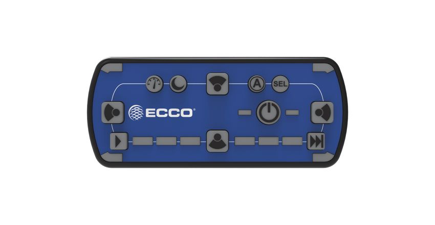
Provides convenient control of the lightbar’s built-in flash patterns and features soft touch buttons and LED function indicator lights.
12+ PRO
12+ ADVANCED
PRO ADVANCED CONTROLLER FUNCTIONS
CONTROLLER FUNCTIONS
ECCOESG.com P/N EZ1202
TogglePress
Toggle Press[Press
/ Pressfor
for22Seconds]
Seconds
Dim Select
Select FlashPattern
Flash Pattern 11
DIM Take Down
Takedown No
Cruise
Cruise No Functionality Progrom Flash
Program FlashPattern
Flash Pattern 22
Back
[BackLighting
Lighting] [Front Cut]
Front Cut Functionality
Patterns
Flash Patterns Flash
FlashPattern
Pattern 33
Left Alley
Left Alley Right Alley
Right Alley
[Left Cut]
Left Cut [Right Cut]
Right Cut
Safety Director
Safety Director Work Light
Work Light Safety Director
Safety Director
On/Off
On/Off [Rear Cut]
Rear Cut Pattern Select
Pattern Select
“Power” - Press to cycle through three programmable flash pattern presets. Hold button down to shut down all functions.
Press again to resume.
Off Pattern 1 Pattern 2 Pattern 3
“Cruise” - Press to illuminate all directional modules in steady burn mode.
“Dim Mode” - Toggle press to dim standard flash patterns. Note, this mode will not dim takedown, alley and worklights.
Long-press this button for two seconds to activate or deactivate backlighting on the contrl head.
No Functionality
“Flash Pattern Select” - First, select Pattern 1, 2 or 3 to program by pushing the Power Button.
Next, double press to enter flash pattern select mode and cycle one flash pattern. The 4 corner
LEDs on the controller will mimic the lightbar to give pattern feedback. Press again once to cycle
to the next flash pattern. Press and hold for 3 seconds to return to the prior flash pattern. The
lightbar will store the last flash pattern used to the active preset. After 30 seconds of inactivity
in Select mode, the control head will automatically exit Select mode.
Page 8 of 14“SafetyDirectorOn/O-” - Press once to turn the Safety Director on or off.
“Safety Director Pattern Select” - Once the Saftey Director is activated, press this pattern select button to cycle to the
next Safety Director flash pattern. There is a 5 second delay between the controller
and the lightbar. Press and hold for 3 seconds to return to the prior flash pattern.
The lightbar will store the last flash pattern used.
“Front Worklight (Takedown)” - Toggle press will activate/deactivate front worklight function. Long press for two seconds
to activate/deactivate front cut.
“Back Worklight” - Toggle press will activate/deactivate rear worklight function. Long press for two seconds to activate/
deactivate back cut.
“Left Worklight (Alley)” - Toggle press will activate/deactivate rear left worklight function. Long press for two seconds
to activate/deactivate left cut.
“Right Worklight (Alley)” - Toggle press will activate/deactivate right worklight function. Long press for two seconds to
activate/deactivate right cut.
Special Features:
Touchpad Backlight
Reset the Lightbar back to Factory Setting: Press SEL button 8 times. The lightbar will flash 3 times and will reset back to
factory settings.
To limit the lightbar to R65 flash patterns, press SEL 5 times and bar will flash twice.
Safety Director Module Selection
To change the number of modules used in the safety director, press and hold - tap to select
5 to 10 modules.
Example
5 6 7 8 9 10 5 6 7 8 9 10
7 modules 9 modules
Safety Director Front/Rear Selection
Press to turn on the safety director.
Press and hold , once the corner LEDs light, tap to cycle front, rear or both.
Page 9 of 14Advanced Control Pad Mounting:
The advanced control pad is supplied with three mounting options: a BRACKET
BRACKET
bracket, VHB tape and hook and loop patch. The rear of the control
pad is designed to allow for the cable exit to be routed five different
ways to maximize installation locations. Mount the control pad in
a location within convenient reach of the operator so that s/he can
operate the system without losing eye contact with the roadway. HOOK AND
HOOK AND
PATCH
LOOP
LOOP
PATCH
TAPETAPE
Advanced Controller Mount (EZ1415):
This holder can easily be mounted in the cab of a vehicle using the
attached suction cup. Control head is placed inside the grips. The
angle of the holder can be changed using the adjustable knobs.
Page 10 of 14Standard Flash Patterns /-Patrones de parpadeo estándar/-Modes de clignotement standard/Standard-
Blitzmuster/Sequenze di segnalazione standard
Standard Flash Patterns J845 J595 CA T13 ECE R65
EZ1203A EZ1203B EZ1203R EZ1203W EZ1203A EZ1203B EZ1203B EZ1203R EZ1203W EZ1203A EZ1203B EZ1203R EZ1203A EZ1203B EZ1203R
Number Flash Pattern EZ1206AX EZ1206BX EZ1206RX EZ1206WX EZ1206AX EZ1206BX EZ1206BX EZ1206RX EZ1206WX EZ1206AX EZ1206BX EZ1206RX EZ1206AX EZ1206BX EZ1206RX
D N D N D N D N D N D N D N D N D N D D D D D D
1 Double 75 FPM ‐ DEFFAULT PATTERN FOR LEVEL 1 C1 C1 C1 C1 C1 C1 C1 C1 C1 ‐ C1 ‐ C1 ‐ C1 ‐ C2 ‐ ‐ CLASS B CLASS B ‐ ‐ ‐
2 Title 13 Quad 65 FPM ‐ DEFFAULT PATTERN FOR LEVEL 2 C1 C1 C1 C1 C1 C1 C1 C1 C1 ‐ C1 ‐ C1 ‐ C1 ‐ C1 ‐ CLASS E CLASS B CLASS B ‐ ‐ ‐
3 Title 13 Double 65 FPM C1 C1 C1 C1 C1 C1 C1 C1 C1 ‐ C1 ‐ C1 ‐ C1 ‐ C1 ‐ CLASS E CLASS B CLASS B ‐ ‐ ‐
4 Quint Hold 75 FPM ‐ DEFFAULT PATTERN FOR LEVEL 3 C1 C1 C1 C1 C1 C1 C1 C1 C1 ‐ C1 ‐ C1 ‐ C1 ‐ C1 ‐ ‐ CLASS B CLASS B ‐ ‐ ‐
5 Pulse 8 Burst 75 FPM C1 C1 C1 C2 C1 C1 C1 C2 C1 ‐ C1 ‐ C1 ‐ C1 ‐ C2 ‐ ‐ ‐ ‐ ‐ ‐ ‐
6 Quad Alternate S S 150 FPM C1S C1S C1S C1S C1S C1S C1S C1S ‐ ‐ ‐ ‐ ‐ ‐ ‐ ‐ ‐ ‐ ‐ ‐ ‐ ‐ ‐ ‐
7 Quad Cross Alternate 150 FPM C1S C1S C1S C1S C1S C1S C1S C1S ‐ ‐ ‐ ‐ ‐ ‐ ‐ ‐ ‐ ‐ ‐ ‐ ‐ ‐ ‐ ‐
8 Double Alternate S S 150 FPM C1S C1S C1S C1S C1S C1S C1S C1S ‐ ‐ ‐ ‐ ‐ ‐ ‐ ‐ ‐ ‐ ‐ ‐ ‐ ‐ ‐ ‐
9 Double Cross Alternate 150 FPM C1S C1S C1S C1S C1S C1S C1S C1S ‐ ‐ ‐ ‐ ‐ ‐ ‐ ‐ ‐ ‐ ‐ ‐ ‐ ‐ ‐ ‐
10 Quint Hold Alternate S S 150 FPM C1S C1S C1S C1S C1S C1S C1S C1S ‐ ‐ ‐ ‐ ‐ ‐ ‐ ‐ ‐ ‐ ‐ ‐ ‐ ‐ ‐ ‐
11 Quint Hold Cross Alternate 150 FPM C1S C1S C1S C1S C1S C1S C1S C1S ‐ ‐ ‐ ‐ ‐ ‐ ‐ ‐ ‐ ‐ ‐ ‐ ‐ ‐ ‐ ‐
12 Quad Alternate S S 150 FPM Center Pulse C1S C1S C1S C1S C1S C1S C1S C1S ‐ ‐ ‐ ‐ ‐ ‐ ‐ ‐ ‐ ‐ ‐ ‐ ‐ ‐ ‐ ‐
13 Double Alternate S S 150 FPM Center Pulse C1S C1S C1S C1S C1S C1S C1S C1S ‐ ‐ ‐ ‐ ‐ ‐ ‐ ‐ ‐ ‐ ‐ ‐ ‐ ‐ ‐ ‐
14 Quint Hold Alternate S S 150 FPM Center Pulse C1S C1S C1S C1S C1S C1S C1S C1S ‐ ‐ ‐ ‐ ‐ ‐ ‐ ‐ ‐ ‐ ‐ ‐ ‐ ‐ ‐ ‐
15 Fast Rotate ‐ ‐ ‐ ‐ ‐ ‐ ‐ ‐ ‐ ‐ ‐ ‐ ‐ ‐ ‐ ‐ ‐ ‐ ‐ ‐ ‐ ‐ ‐ ‐
16 Wave Rotate ‐ ‐ ‐ ‐ ‐ ‐ ‐ ‐ ‐ ‐ ‐ ‐ ‐ ‐ ‐ ‐ ‐ ‐ ‐ ‐ ‐ ‐ ‐ ‐
17 Rotate Quad ‐ ‐ ‐ ‐ ‐ ‐ ‐ ‐ ‐ ‐ ‐ ‐ ‐ ‐ ‐ ‐ ‐ ‐ ‐ ‐ ‐ ‐ ‐ ‐
18 Fast Quad ‐ ‐ ‐ ‐ ‐ ‐ ‐ ‐ ‐ ‐ ‐ ‐ ‐ ‐ ‐ ‐ ‐ ‐ ‐ ‐ ‐ ‐ ‐ ‐
19 Airport Flash 75 FPM ‐ ‐ ‐ ‐ ‐ ‐ ‐ ‐ ‐ ‐ ‐ ‐ ‐ ‐ ‐ ‐ ‐ ‐ ‐ ‐ ‐ ‐ ‐ ‐
20 Steady White Left ‐ ‐ ‐ ‐ ‐ ‐ ‐ ‐ ‐ ‐ ‐ ‐ ‐ ‐ ‐ ‐ ‐ ‐ ‐ ‐ ‐ ‐ ‐ ‐
21 Steady White Right ‐ ‐ ‐ ‐ ‐ ‐ ‐ ‐ ‐ ‐ ‐ ‐ ‐ ‐ ‐ ‐ ‐ ‐ ‐ ‐ ‐ ‐ ‐ ‐
22 Steady White Front ‐ ‐ ‐ ‐ ‐ ‐ ‐ ‐ ‐ ‐ ‐ ‐ ‐ ‐ ‐ ‐ ‐ ‐ ‐ ‐ ‐ ‐ ‐ ‐
23 Steady White Rear ‐ ‐ ‐ ‐ ‐ ‐ ‐ ‐ ‐ ‐ ‐ ‐ ‐ ‐ ‐ ‐ ‐ ‐ ‐ ‐ ‐ ‐ ‐ ‐
24 Title 13 Steady Single Front Red ‐ ‐ ‐ ‐ ‐ ‐ ‐ ‐ ‐ ‐ ‐ ‐ ‐ ‐ ‐ ‐ ‐ ‐ ‐ ‐ CLASS B ‐ ‐ ‐
25 Title 13 Steady Single Front Blue ‐ ‐ ‐ ‐ ‐ ‐ ‐ ‐ ‐ ‐ ‐ ‐ ‐ ‐ ‐ ‐ ‐ ‐ ‐ CLASS B ‐ ‐ ‐ ‐
26 Title 13 Steady Single Front Red and Blue ‐ ‐ ‐ ‐ ‐ ‐ ‐ ‐ ‐ ‐ ‐ ‐ ‐ ‐ ‐ ‐ ‐ ‐ ‐ ‐ CLASS B ‐ ‐ ‐
27 4‐LED, Left, 2000 with 250 off. ‐ ‐ ‐ ‐ ‐ ‐ ‐ ‐ ‐ ‐ ‐ ‐ ‐ ‐ ‐ ‐ ‐ ‐ ‐ ‐ ‐ ‐ ‐ ‐
28 4‐LED, Left Solid, 2000 with 250 off. ‐ ‐ ‐ ‐ ‐ ‐ ‐ ‐ ‐ ‐ ‐ ‐ ‐ ‐ ‐ ‐ ‐ ‐ ‐ ‐ ‐ ‐ ‐ ‐
29 4‐LED, LeftFillAndChase, 2000 with 250 off. ‐ ‐ ‐ ‐ ‐ ‐ ‐ ‐ ‐ ‐ ‐ ‐ ‐ ‐ ‐ ‐ ‐ ‐ ‐ ‐ ‐ ‐ ‐ ‐
30 4‐LED, Right, 2000 with 250 off. ‐ ‐ ‐ ‐ ‐ ‐ ‐ ‐ ‐ ‐ ‐ ‐ ‐ ‐ ‐ ‐ ‐ ‐ ‐ ‐ ‐ ‐ ‐ ‐
31 4‐LED, Right Solid, 2000 with 250 off. ‐ ‐ ‐ ‐ ‐ ‐ ‐ ‐ ‐ ‐ ‐ ‐ ‐ ‐ ‐ ‐ ‐ ‐ ‐ ‐ ‐ ‐ ‐ ‐
32 4‐LED, RightFillAndChase, 2000 with 250 off. ‐ ‐ ‐ ‐ ‐ ‐ ‐ ‐ ‐ ‐ ‐ ‐ ‐ ‐ ‐ ‐ ‐ ‐ ‐ ‐ ‐ ‐ ‐ ‐
33 4‐LED, Center Out, 1000 with 250 off, 2 repeats. ‐ ‐ ‐ ‐ ‐ ‐ ‐ ‐ ‐ ‐ ‐ ‐ ‐ ‐ ‐ ‐ ‐ ‐ ‐ ‐ ‐ ‐ ‐ ‐
34 4‐LED, Center Out Solid, 1000 with 250 off, 2 repeats. ‐ ‐ ‐ ‐ ‐ ‐ ‐ ‐ ‐ ‐ ‐ ‐ ‐ ‐ ‐ ‐ ‐ ‐ ‐ ‐ ‐ ‐ ‐ ‐
35 4‐LED, CenterFillAndChase, 1000 with 250 off, 2 repeats. ‐ ‐ ‐ ‐ ‐ ‐ ‐ ‐ ‐ ‐ ‐ ‐ ‐ ‐ ‐ ‐ ‐ ‐ ‐ ‐ ‐ ‐ ‐ ‐
36 4‐LED, Quad Flash, 1000 with 83 on and 42 off, 2 sets of 4 repeats. ‐ ‐ ‐ ‐ ‐ ‐ ‐ ‐ ‐ ‐ ‐ ‐ ‐ ‐ ‐ ‐ ‐ ‐ ‐ ‐ ‐ ‐ ‐ ‐
37 4‐LED, Wig Wag, 500 with 250 on and 250 off, 4 repeats. ‐ ‐ ‐ ‐ ‐ ‐ ‐ ‐ ‐ ‐ ‐ ‐ ‐ ‐ ‐ ‐ ‐ ‐ ‐ ‐ ‐ ‐ ‐ ‐
38 4‐LED, Alternating, 500 with 250 on and 250 off, 4 repeats. ‐ ‐ ‐ ‐ ‐ ‐ ‐ ‐ ‐ ‐ ‐ ‐ ‐ ‐ ‐ ‐ ‐ ‐ ‐ ‐ ‐ ‐ ‐ ‐
39 Reg 65 Single 120 FPM, 2.05 Hz C1 C1 C1 C1 C1 C1 C1 C1 C1 ‐ C1 ‐ C1 ‐ C1 ‐ C2 ‐ ‐ ‐ ‐ CLASS 1 CLASS 1 CLASS 1
40 Reg 65 Double 120 FPM, 2.05 Hz C1 C1 C1 C1 C1 C1 C1 C1 C1 ‐ C1 ‐ C1 ‐ C1 ‐ C2 ‐ ‐ ‐ ‐ CLASS 1 CLASS 1 CLASS 1
41 Reg 65 Triple 120 FPM, 2.05 Hz C1 C1 C1 C1 C1 C1 C1 C1 C1 ‐ C1 ‐ C1 ‐ C1 ‐ C2 ‐ ‐ ‐ ‐ CLASS 1 CLASS 1 CLASS 1
42 Reg 65 Quad 120 FPM, 2.05 Hz C1 C1 C1 C1 C1 C1 C1 C1 C1 ‐ C1 ‐ C1 ‐ C1 ‐ C2 ‐ ‐ ‐ ‐ CLASS 1 CLASS 1 CLASS 1
43 Reg 65 Burst 120 FPM, 2.05 Hz C1 C1 C1 C1 C1 C1 C1 C1 C1 ‐ C1 ‐ C1 ‐ C1 ‐ C2 ‐ ‐ ‐ ‐ CLASS 1 CLASS 1 CLASS 1
44 Reg 65 Single S S 120 FPM, 2.05 Hz C1 C1 C1 C1 C1 C1 C1 C1 C1 ‐ C1 ‐ C1 ‐ C1 ‐ C2 ‐ ‐ ‐ ‐ CLASS 1 CLASS 1 CLASS 1
45 Reg 65 Double S S 120 FPM, 2.05 Hz C1 C1 C1 C1 C1 C1 C1 C1 C1 ‐ C1 ‐ C1 ‐ C1 ‐ C2 ‐ ‐ ‐ ‐ CLASS 1 CLASS 1 CLASS 1
46 Reg 65 Triple S S 120 FPM, 2.05 Hz C1 C1 C1 C1 C1 C1 C1 C1 C1 ‐ C1 ‐ C1 ‐ C1 ‐ C2 ‐ ‐ ‐ ‐ CLASS 1 CLASS 1 CLASS 1
47 Reg 65 Quad S S 120 FPM, 2.05 Hz C1 C1 C1 C1 C1 C1 C1 C1 C1 ‐ C1 ‐ C1 ‐ C1 ‐ C2 ‐ ‐ ‐ ‐ CLASS 1 CLASS 1 CLASS 1
48 Reg 65 Burst S S 120 FPM, 2.05 Hz C1 C1 C1 C1 C1 C1 C1 C1 C1 ‐ C1 ‐ C1 ‐ C1 ‐ C2 ‐ ‐ ‐ ‐ CLASS 1 CLASS 1 CLASS 1
49 Reg 65 Single S S 120 FPM Center Pulse, 2.05 Hz C1 C1 C1 C1 C1 C1 C1 C1 C1 ‐ C1 ‐ C1 ‐ C1 ‐ C2 ‐ ‐ ‐ ‐ ‐ ‐ ‐
50 Reg 65 Double S S 120 FPM Center Pulse, 2.05 Hz C1 C1 C1 C1 C1 C1 C1 C1 C1 ‐ C1 ‐ C1 ‐ C1 ‐ C2 ‐ ‐ ‐ ‐ ‐ ‐ ‐
51 Reg 65 Triple S S 120 FPM Center Pulse, 2.05 Hz C1 C1 C1 C1 C1 C1 C1 C1 C1 ‐ C1 ‐ C1 ‐ C1 ‐ C2 ‐ ‐ ‐ ‐ ‐ ‐ ‐
52 Reg 65 Quad S S 120 FPM Center Pulse, 2.05 Hz C1 C1 C1 C1 C1 C1 C1 C1 C1 ‐ C1 ‐ C1 ‐ C1 ‐ C2 ‐ ‐ ‐ ‐ ‐ ‐ ‐
53 Reg 65 Burst S S 120 FPM Center Pulse, 2.05 Hz C1 C1 C1 C1 C1 C1 C1 C1 C1 ‐ C1 ‐ C1 ‐ C1 ‐ C2 ‐ ‐ ‐ ‐ ‐ ‐ ‐
54 Cycle All ‐ ‐ ‐ ‐ ‐ ‐ ‐ ‐ ‐ ‐ ‐ ‐ ‐ ‐ ‐ ‐ ‐ ‐ ‐ ‐ ‐ ‐ ‐ ‐
55 Steady PWM 50 ‐ ‐ ‐ ‐ ‐ ‐ ‐ ‐ ‐ ‐ ‐ ‐ ‐ ‐ ‐ ‐ ‐ ‐ ‐ ‐ ‐ ‐ ‐ ‐
Safety Director™ Flash Patterns /Patrones de parpadeo Safety Director™/-Modes de clignotement de NOTE:
Safety
SafetyDirector™/-Safety
Director FlashDirector™-Leuchtmuster/Sequenze
Patterns di segnalazione del Safety Director™
1. All SAE J845 compliant patterns have at least 180° of coverage with the minimum configuration of two corner modules, one forward facing and one rear facing module.
Number Name
1 Left Cut NOTA:
2 Right Cut 1. Todos los patrones que cumplen con SAE J845 tienen al menos 180 ° de cobertura con la configuración mínima de dos módulos de esquina, uno orientado hacia adelante y un módulo
3 Left and Right Cut orientado hacia atrás.
4 Front Cut
5 Front and Left Cut REMARQUE:
1. Tous les modèles conformes SAE J845 ont une couverture d’au moins 180° avec la configuration minimale de deux modules d’angle, un module orienté vers l’avant et un module orienté
6 Front and Right Cut
vers l’arrière.
7 Front and Left and Right Cut
8 Rear Cut HINWEIS:
9 Rear and Left Cut 1. Alle SAE J845-konformen Muster haben eine Abdeckung von mindestens 180° mit der Mindestkonfiguration von zwei Eckmodulen, einem nach vorne und einem nach hinten gerichteten
10 Rear and Right Cut Modul.
11 Rear and Left and Right Cut
12 Front and Rear Cut NOTA:
1. Tutti i modelli conformi a SAE J845 hanno almeno 180° di copertura con la configurazione minima di due moduli angolari, uno rivolto in avanti e uno rivolto all’indietro.
Page 11 of 14Replacement Parts/Accessories
Description Part No.
Lenses
Replacement 24" End Lens - Clear ER0003
Replacement 6" Mid Lens - Clear ER0004
Driver PCA
12 Channel Driver Board Call ECCO Rep
20 Channel Driver Board Call ECCO Rep
Led Modules
3-LED Ice Optic Module - Amber EZ1203A
3-LED Ice Optic Module - Blue EZ1203B
3-LED Ice Optic Module - Green EZ1203G
3-LED Ice Optic Module - Red EZ1203R
3- LED Ice Optic Module - White EZ1203W
4-LED Worklight / Alley Light Module Pair - White EZ0003
6-LED Flare Optic Stop / Turn / Tail (STT) Module Pair - Red EZ1205
6-LED Ice Optic Dual Color Module - Amber / Blue EZ1206AB
6-LED Ice Optic Dual Color Module - Amber / Red EZ1206AR
6-LED Ice Optic Dual Color Module - Amber / White EZ1206AW
6-LED Ice Optic Dual Color Module - Blue / White EZ1206BW
6-LED Ice Optic Dual Color Module - Red / Blue EZ1206RB
6-LED Ice Optic Dual Color Module - Red / White EZ1206RW
Cables
15' Extension Cable - For use with Standard Wiring EZ0008
23' Extension Cable - For use with Standard Wiring EZ0008-23
48' Extension Cable - For use with Standard Wiring EZ0008-48
15' Extension Cable - For use with Advanced Controller EZ1202 EZ1210
48' Extension Cable - For use with Advanced Controller EZ1202 EZ1413-48
15' Power Cable ER0020
6" Discrete Wiring Harness (Pigtail) - For use with Standard Wiring ER0021
Control Options
Advanced Controller EZ1202
Serial Interface Box (SIB) EZMATSIB
Remote Rocker Max Pak™, 6 button controller 450R-L6
6-Rocker Switch Panel A9000
Single Illuminated Rocker Switch A9891
Single Switch Panel - For use with A9891 Switch A9893
Single Illuminate Rocker Switch A9901
End Switch Panel Section - For use with A9901 Switch A9902
Center Switch Panel Section - For use with A9901 Switch & End Panel Sections A9902 A9903
Switch Panel Mounting Kit - For use with A9901 Switch & Panel Sections A9902 & A9903 A9904
On / Off Switch Panel with Pattern Select A9905SW
Mounting Kits
Permanent mounting feet and hardware - Black ER0002
Permanent mounting feet and hardware - White ER0001
Headache rack mounting kit A1032RMK
NOTE: For list of vehicle specific brackets, please contact an ECCO representative or our latest catelog.
Page 12 of 14Troubleshooting
All lightbars are thoroughly tested prior to shipment. However, should you encounter a problem during installation or during the life of the
product, follow the guide below for troubleshooting and repair information. If the problem cannot be rectified using the solutions given below,
additional information may be obtained from the manufacturer – contact details are at the end of this document.
LIGHTBAR AND CONTROLLER
PROBLEM POSSIBLE CAUSE SOLUTION
If controller functions normally, or if a 12/24V control voltage is present on
either the Pattern 1 (brown) or Pattern 2 (orange) wires, then replace the
Poor power or ground connection driver board in the lightbar.
Does not function If controller does not function, then check fuse, cables, and connections to
the lightbar and to the controller.
Blown fuse Check wiring, replace fuse
One or two LED head do not flash, Open circuit wiring from control mod- Connect a known-good LED head to the problem output to ensure the con-
but Pattern 1 or Pattern 2 indicator ule to LED head trol module is working correctly. Repair or replace.
LED on control module is on. Failed LED head Replace LED head
LED head flashes dimly Defective head or driver board Check correct LED head
Incorrect flash patterns Re-program the lightbar flash pattern for either Program 1 or Program 2, or
Wrong flash configuration
both.
Secondary pattern does not function Normal operation Primary function overrides secondary function – turn off primary function
ALLEY / TAKEDOWN / WORKLIGHTS
PROBLEM POSSIBLE CAUSE SOLUTION
Defective light Replace light
Light does not function If indicator LED on controller is lit, then it is either the light, or the
Defective controller cable to the light, or the driver board. Otherwise the controller is
defective.
STOP/TAIL/TURN
PROBLEM POSSIBLE CAUSE SOLUTION
Blown fuse Check wiring, replace fuse
No power Check to see if vehicle S/T/T lights function properly
Both/all lights do not function
Make sure that the S/T/T head is plugged into the S/T/T control board
Failed S/T/T LED head
and not the driver board. Replace S/T/T LED head and/or its cable.
Page 13 of 14NOTE: Operating the vehicle without the outer lens installed
on the product may result in damage that will NOT be
covered under warranty.
Manufacturer Limited Warranty and Limitation of Liability:
Manufacturer warrants that on the date of purchase, this product will conform to Manufacturer’s specifications for this product (which are available from the
Manufacturer upon request). This Limited Warranty extends for sixty (60) months from the date of purchase.
DAMAGE TO PARTS OR PRODUCTS RESULTING FROM TAMPERING, ACCIDENT, ABUSE, MISUSE, NEGLIGENCE, UNAPPROVED
MODIFICATIONS, FIRE OR OTHER HAZARD; IMPROPER INSTALLATION OR OPERATION; OR NOT BEING MAINTAINED IN ACCORDANCE WITH
THE MAINTENANCE PROCEDURES SET FORTH IN MANUFACTURER’S INSTALLATION AND OPERATING INSTRUCTIONS VOIDS THIS LIMITED
WARRANTY.
Exclusion of Other Warranties:
MANUFACTURER MAKES NO OTHER WARRANTIES, EXPRESSED OR IMPLIED. THE IMPLIED WARRANTIES FOR MERCHANTABILITY, QUALITY
OR FITNESS FOR A PARTICULAR PURPOSE, OR ARISING FROM A COURSE OF DEALING, USAGE OR TRADE PRACTICE ARE HEREBY
EXCLUDED AND SHALL NOT APPLY TO THE PRODUCT AND ARE HEREBY DISCLAIMED, EXCEPT TO THE EXTENT PROHIBITED BY APPLICABLE
LAW. ORAL STATEMENTS OR REPRESENTATIONS ABOUT THE PRODUCT DO NOT CONSTITUTE WARRANTIES.
Remedies and Limitation of Liability:
MANUFACTURER’S SOLE LIABILITY AND BUYER’S EXCLUSIVE REMEDY IN CONTRACT, TORT (INCLUDING NEGLIGENCE), OR UNDER ANY
OTHER THEORY AGAINST MANUFACTURER REGARDING THE PRODUCT AND ITS USE SHALL BE, AT MANUFACTURER’S DISCRETION,
THE REPLACEMENT OR REPAIR OF THE PRODUCT, OR THE REFUND OF THE PURCHASE PRICE PAID BY BUYER FOR NON-CONFORMING
PRODUCT. IN NO EVENT SHALL MANUFACTURER’S LIABILITY ARISING OUT OF THIS LIMITED WARRANTY OR ANY OTHER CLAIM RELATED TO
THE MANUFACTURER’S PRODUCTS EXCEED THE AMOUNT PAID FOR THE PRODUCT BY BUYER AT THE TIME OF THE ORIGINAL PURCHASE.
IN NO EVENT SHALL MANUFACTURER BE LIABLE FOR LOST PROFITS, THE COST OF SUBSTITUTE EQUIPMENT OR LABOR, PROPERTY
DAMAGE, OR OTHER SPECIAL, CONSEQUENTIAL, OR INCIDENTAL DAMAGES BASED UPON ANY CLAIM FOR BREACH OF CONTRACT,
IMPROPER INSTALLATION, NEGLIGENCE, OR OTHER CLAIM, EVEN IF MANUFACTURER OR A MANUFACTURER’S REPRESENTATIVE HAS BEEN
ADVISED OF THE POSSIBILITY OF SUCH DAMAGES. MANUFACTURER SHALL HAVE NO FURTHER OBLIGATION OR LIABILITY WITH RESPECT
TO THE PRODUCT OR ITS SALE, OPERATION AND USE, AND MANUFACTURER NEITHER ASSUMES NOR AUTHORIZES THE ASSUMPTION OF
ANY OTHER OBLIGATION OR LIABILITY IN CONNECTION WITH SUCH PRODUCT.
This Limited Warranty defines specific legal rights. You may have other legal rights which vary from jurisdiction to jurisdiction. Some jurisdictions do not
allow the exclusion or limitation of incidental or consequential damages.
APPROVALS DATE
DRAWN BY BTK 2021-09-23
CHECKED - -
MECH. ENG. - -
ELEC. ENG - -
TEST ENG. - -
PRODUCTION - -
MARKETING - -
833 West Diamond Street 439 Boundary Road Unit 1, Green Park, Coal Road
Boise, Idaho 83705 Truganina Victoria, Australia Seacroft, Leeds, England LS14 1FB
800-635-5900 +61 (0)3 8336 0680 +44 (0)113 2375340
orders@eccogroup.com esgapsales@eccogroup.com esguk-code3@eccogroup.com
ECCOESG.com ECCOESG.com/au/en ECCOESG.co.uk
An ECCO SAFETY GROUP™ Brand
ECCOSAFETYGROUP.com
© 2021 ECCO, Inc. All rights reserved.
920-0909-00 Rev. D Page 14 of 14Instrucciones de instalación y operación
Barra de luces de la serie Pro
Vantage™ 12+
¡IMPORTANTE!Leatodaslasinstruccionesantesdeinstalaryutilizar.Instalador:Estemanualsedebeentregaralusuariofinal.
¡ADVERTENCIA!
Si no sigue las instrucciones del fabricante a la hora de instalar o usar el producto, pueden producirse daños materiales, y lesiones
graves o incluso mortales a aquellos que pretende proteger!
No instale ni opere este producto de seguridad, a menos que haya leído y comprendido la información de
seguridad contenida en este manual.
1. Para garantizar su propia seguridad y la de las personas a las que intenta proteger, es esencial una instalación correcta, combinada con
la formación de operador en el uso, cuidado y mantenimiento de los dispositivos de alerta de emergencia.
2. Tenga cuidado cuando manipule conexiones eléctricas con corriente.
3. Este producto debe estar conectado a tierra correctamente. Una conexión a tierra incorrecta o unas conexiones eléctricas
cortocircuitadas pueden provocar arcos de corriente alta, lo que puede ocasionar lesiones personales o daños graves en el vehículo,
incluso un incendio.
4. La colocación e instalación adecuadas son vitales para el buen funcionamiento de este dispositivo de alarma. Instale este producto
de forma que permita un rendimiento óptimo del sistema y los controles estén situados de modo que el operador pueda alcanzarlos
cómodamente y manejar el sistema sin perder en ningún momento el contacto visual con la calzada.
5. No instale este producto ni coloque los cables en la zona de despliegue de un airbag. Si el equipo se monta o coloca en la zona de
desplieguedeunairbag,elairbagperderáeficaciaoelequipopuedesalirdespedido,locualpuedecausarlesionesgravesoinc
mortales. Consulte el manual del propietario del vehículo para conocer la zona de despliegue de los airbags. El usuario u operador son
responsables de determinar una posición de montaje adecuada que garantice la seguridad de todos los ocupantes del vehículo, y deben
evitar zonas que puedan provocar golpes en la cabeza.
6. Es responsabilidad del operador del vehículo asegurarse de que todas las características de este producto funcionan correctamente
durante su uso. Durante su uso, el operador del vehículo debe asegurarse de que no haya componentes del vehículo (como los maleteros
o puertas del habitáculo abiertos), personas, vehículos u otros obstáculos que bloqueen la señal de alarma.
7. El uso de este o cualquier otro dispositivo de alarma no garantiza que los conductores puedan o quieran observar o reaccionar a la señal
de alarma. Nunca dé por hecho que tiene prioridad de paso. Es responsabilidad enteramente suya asegurarse de que puede continuar
de forma segura antes de entrar en una intersección, conducir en sentido contrario, responder a una gran velocidad o caminar por los
carrilesdetráficoocercadeellos.
8. El uso de este equipo está destinado exclusivamente a personal autorizado. El usuario es responsable de conocer y acatar todas las
leyes vigentes relacionadas con dispositivos de señales de advertencia. Por lo tanto, el usuario debe comprobar todas las leyes y
normativas de ámbito metropolitano, regional, nacional y cualquier otro ámbito pertinente. El fabricante no asume responsabilidad alguna
por pérdidas derivadas del uso de este dispositivo de alarma.
Especificaciones
Longitud..............................61 cm (24”), 76 cm (30”), 91 cm (36”), 107 cm (42”), 122 cm (48”), 137 cm (54”), 152 cm (60”), 183 cm (72”)
Anchura..............................28 cm (11”)
Altura................................. 6 cm (2,5”)
Tensión...............................12-24 V CC
Consumo de corriente........Módulo LED monocromo = 0,55 A de media a 12,8 V CC Módulo LED de dos colores = 0,55 A de media a 12,8 V CC LED de luces
de freno, traseras e intermitentes (par) = 1,2 A de media a 12,8 V CC LED de luces laterales, frontales y de trabajo = 1,2 A de media
a 12,8 V CC
Patrón de destello..............70
Fusible recomendado:
Calcule el consumo total de corriente de todos los módulos LED.
Multiplique el consumo total de corriente por 1,25. Redondee al alza
hasta el fusible más cercano.
Página 1 de 13Instalación y montaje
Desembalaje y preinstalación
Retire con cuidado la barra luminosa y colóquela sobre una superficie plana. Examine la unidad por si se ha dañado durante el transporte y
compruebe que están todas las piezas. Si hay daños o faltan piezas, póngase en contacto con la empresa de transporte o ECCO. No utilice
piezas dañadas o rotas. Asegúrese de que la tensión de la barra luminosa sea compatible con la instalación prevista.
Montaje
Antes de continuar con la instalación, planifique todo el cableado y el tendido de los cables. Para montar la barra luminosa, seleccione una
superficie plana y lisa, y centre la unidad a lo ancho del vehículo. A la hora de montar la barra luminosa, debe seleccionarse una ubicación en la
que dicha barra quede nivelada y sea perfectamente visible para el resto de usuarios de la vía. Tras el montaje, la separación entre el techo y la
barra luminosa no debe ser superior a 1,27 cm (½”) en ningún punto.
¡PRECAUCIÓN!
Alperforarcualquiersuperficiedelvehículo,asegúresede
que no haya cables eléctricos, mangueras de combustible,
tapicería, etc. en el área que pudiesen dañarse.
Montaje permanente
1. Determine la ubicación de la barra luminosa y el mejor lugar para disponer los cables. Efectúe la instalación en la parte estructural del
techo o la superficie menos flexible.
2. Determine la posición de las patas de montaje y perfore los orificios de montaje de 5/16”-11/32” de diámetro, si es necesario. Es posible
ajustar la separación de las patas de montaje de izquierda a derecha. Es recomendable que la posición de las patas sea simétrica y
próxima a los bordes curvos del techo, donde el techo es más fuerte. Lo ideal es utilizar para la instalación los orificios de las patas
situados en la parte exterior.
3. Monte la barra luminosa colocando los pernos en los orificios taladrados en el paso 2 y pasando los cables según lo previsto en el
paso 1 (consulte el diagrama). Consulte la sección Cableado de este manual para obtener más instrucciones sobre el cableado. Instale
las arandelas y las tuercas, y asegure la unidad.
7.86”
5.31”
LIGHTBAR
BARRA DE LUCES
PERNO DE CABEZA REDONDA
5/16” COACH BOLT
DE 8 MM
MOUNTINGDE
SUPERFICIE SURFACE
MONTAJE (RECORTE)
(CUT OUT)
LOAD WASHER
ARANDELA DE CARGA
TUERCA MECÁNICA DE
5/16” NYLOCK NUT
SEGURIDAD DE 8 MM
Página 2 de 13Gutter Mounting
¡IMPORTANTE! Esta unidad es un dispositivo de seguridad y se debe conectar a su propia fuente de poder de fusibles separada para asegurar
su funcionamiento continuo si cualquier otro accesorio eléctrico falla.
1. Quite la pata de montaje. Coloque el soporte en los salientes de la pata.
2. Sujete el soporte y la pata, e inserte la tuerca de jaula como se muestra. Se ajustará sin problemas debajo de la pata de montaje. No la
instale en la cara exterior.
3. Instale las patas de montaje en el orden inverso al de extracción. El soporte de metal quedará entre la barra y la pata de montaje de
composite. Ajuste la separación de las patas de montaje antes de apretar firmemente las tuercas.
4. Pase el perno M6 por la arandela y la correa de montaje y apriételo a mano en la tuerca de jaula. No pase la rosca del perno y no lo
apriete por completo de momento.
5. Una vez que la barra esté en su posición, utilice la correa como plantilla para perforar los orificios de Ø1/8”. Es posible que sea necesa-
rio retirar el burlete de la puerta o el guarnecido. Aplique silicona o sellador alrededor del orificio y por detrás de la correa. Asegure las
correas con los tornillos rosca chapa de acero inoxidable del 10 y las arandelas tal como se muestra. Los tornillos deben apretarse a
aproximadamente 5-10 in-lb.
6. Apriete los pernos M6 de manera uniforme para que la barra quede nivelada y centrada. Vuelva a colocar el guarnecido o el burlete que
haya tenido que retirar y cierre las puertas para comprobar si la barra luminosa ha quedado bien ajustada.
BARRA DE LUCES
LIGHTBAR
PATA DE MONTAJE
MOUNTING FOOT 5/16”
PERNOSHEX HEXAGONALES
BOLTS DE 8 MM
M6 SCREW
TORNILLO M6 ARANDELA DE
M6ESTRELLA
STAR WASHER SOPORTE
FOOT DE PATA
BRACKET
M6
MOUNTING
CORREA DE TUERCA
M6 CAGE EN
NUTJAULA M6
MONTAJE
STRAP
ARANDELAS
5/16” PLANAS DE 8 mm
FLAT WASHERS
ARANDELAS
5/16” HENDIDAS
SPLIT LOCK WASHERSDE 8 mm
5/16” HEX HEXAGONALES
TUERCAS NUTS DE 8 mm
TECHO
VEHICLEDEL
ROOFVEHÍCULO
ARANDELAS DE ORIFICIO DE 3,2 mm
Ø1/8” HOLES
#10 STAR WASHERS
ESTRELLA DEL 10
SHEET METALROSCA
TORNILLOS SCREWSCHAPA
Página 3 de 13Instrucciones de cableado
¡IMPORTANTE! Esta unidad es un dispositivo de seguridad y se debe conectar a su propia fuente de poder de fusibles separada para asegurar
su funcionamiento continuo si cualquier otro accesorio eléctrico falla.
Notas:
1. Los cables más largos y las conexiones bien ajustadas ofrecerán una mayor vida útil a los componentes. Para cables de alta corriente, se
recomienda usar bloques de terminales o conexiones soldadas cuando se intube por contracción para proteger las conexiones. No usa
conectores de por desplazamiento en aislamiento (p. ej., conectores tipo Scotchlock de 3M)
2. Enrute el cableado utilizando pasacables y sellante cuando atraviese las paredes del compartimiento. Minimice el número de empalmes
parareducirlacaídadetensión.Lastemperaturasambientealtas(p.ej.,debajodelacajuela)reduciránsignificativamentel
de transmisión de la corriente de cables, fusibles e interruptores. Todo el cableado debe estar en conformidad con el tamaño mínimo de
cableyotrasrecomendacionesdelfabricante,ademásdeestarprotegidodelaspartesmóvilesylassuperficiescalientes.De
mangueras, pasacables, amarres de cables y accesorios similares de instalación para anclar y proteger todo el cableado.
3. Los fusibles o interruptores deben ubicarse tan cerca de los puntos de toma de potencia como sea posible y deben ajustarse al tamaño
exacto para proteger el cableado y los dispositivos.
4. Se debe prestar atención especial a la ubicación y al método para hacer las conexiones eléctricas y empalmes para proteger estos puntos
de la corrosión y la pérdida de conductividad.
5. La puesta a tierra solo debe hacerse a componentes sustanciales del chasis, de preferencia directamente a la batería del vehículo.
6. Los interruptores son muy sensibles a altas temperaturas y “se desconectarán falsamente” cuando se monten en ambientes calientes o
se operen cerca de su capacidad.
PRECAUCIÓN!
Desconecte la batería antes de conectar la barra luminosa para evitar cortocircuitos accidentales, arcos o descargas eléctricas.
Instrucciones generales de cableado
Antes de intentar conectar el mazo de cables de la barra luminosa, consulte el diagrama de cableado que se muestra a continuación. El
diagrama de cableado describe la función de cada cable.
1. Conecte el cable rojo de alimentación de la barra luminosa a un punto de alimentación conmutado con el encendido y protegido por un
fusible. Conecte el cable negro a una conexión a tierra firme del vehículo (lo ideal es conectarlo directamente al terminal negativo de la
batería). Utilice un fusible según el diagrama de cableado.
2. Después de montar la barra luminosa, pase el cable de control al interior del vehículo y conéctelo a un punto del panel de interruptores/
controlador.
3. Conecte los cables del mazo de cables de la barra luminosa al lado conmutado de cada interruptor, o al controlador opcional. Consulte
el diagrama de cableado para obtener información sobre la codificación de funciones y colores de los cables.
4. Utilice bridas y pasacables para asegurar y proteger todos los cables.
CABLEADO ESTÁNDAR (cables discretos para alimentación/conexión a tierra y control)
Pigtal connector
Conector (ER0021)
flexible (ER0021)
Barra de12+ Pro
luces deVantage™
la serie Pro Lightbar
Vantage™ 12+ Control
Cable Cable
de control
Switches de
Interruptores or la
unidad de control
control box
MARRÓN
BROWN(PATRÓN 1) 1)
(PATTERN
Freno, traseras e NARANJA
ORANGE(PATRÓN 2) 2)
(PATTERN
STTs OPTIONAL
intermitentes opcional: Power/Ground Cable tierra
Cable de alimentación/de
Optional Stop/Tail/Turn
cable de freno/traseras/ AMARILLO (LATERAL
YELLOW (ALLEY A LA IZQUIERDA)
LEFT)
(STT) Cable(STT) opcional
intermitentes
VERDE
GREEN(LATERAL A LA DERECHA)
(ALLEY RIGHT)
BROWN(PARTE
MARRÓN (TAIL)POSTERIOR) BLACK
NEGRO
AZUL
BLUE(LUCES DE TRABAJO/FRONTALES)
(WORKLIGHTS/TAKEDOWNS)
AMARILLO (INTERMITENTE NOTE: GREEN AND YELLOW
YELLOW (LEFT TURN)
IZQUIERDO) Nota: Las funciones de los cables VIOLETA
VIOLET(PATRONES
(PROGRAMDE PROGRAMA)
PATTERNS)
WIRE FUNCTIONS ARE
verde y amarillo se intercambian en
VERDE (INTERMITENTE
GREEN (RIGHT TURN)
DERECHO)
SWAPPED
las barras deIN LIGHTBARS
luces WITH
con la salida del RED
ROJO
PASSENGER
cable SIDE
del lado del CABLE EXIT.
acompañante.
Utilice el cable See Fuse las
Consulte
ROJO
RED(FRENO)
(STOP) USE THE REDrojo soloIN
WIRE en3-WIRE
sistemas IGNITION
de 3 cables. recomendaciones on Interruptor de
Recommendations
BLANCO (A TIERRA DE FRENO, SYSTEMS ONLY. Page
sobre1.los fusibles en SWITCH
encendido
WHITE (STT
TRASERAS GROUND)
E INTERMITENTES) la página 1. 1A
NOTE:
Nota: Combine
combine Brown
los cables and
marrón
yOrange wiresel for
naranja para Pattern
patrón 3. 3
Página 4 de 13Programación de cables de alimentación/señal estándar y combinados
TPara cambiar el patrón de destello, aplique alimentación al cable del patrón que desee. A continuación, toque dos veces la alimentación
con el cable violeta para activar el modo de selección de patrón. Toque el lado de alimentación una vez con el cable violeta para pasar por
los distintos patrones de destello. Aísle el cable violeta en cuanto haya seleccionado el patrón.
CABLE DE ALIMENTACIÓN/SEÑAL COMBINADO
Combined
Cable de alimentación/señal
Barra de12+ Pro
luces deVantage™
la serie ProLightbar
Vantage™ 12+ combinado
power/signal cable
Combined
Cable de alimentación/señal
combinado
power/signal cable
NEGRO
BLACK (GROUND)
STTs OPTIONAL
Freno, traseras e
MARRÓN (PATRÓN
BROWN (PATTERN 1) 1)
Optional Stop/Tail/Turn
intermitentes opcional:
cable de
(STT) Cablefreno/traseras/ NARANJA (PATRÓN *Brown
MARRÓN + Orange = Pattern
+ NARANJA (PARTE3 POSTERIOR 3)
intermitentes (STT) opcional ORANGE (PATTERN 2) 2)
AMARILLO (LATERAL
YELLOW (ALLEY A LA IZQUIERDA)
LEFT)
VERDE (LATERAL A LA DERECHA)
GREEN (ALLEY RIGHT)
BROWN(PARTE
MARRÓN (TAIL) POSTERIOR)
GRIS
GREY(ARROWSTIK IZQUIERDA)
(ARROWSTICK LEFT)
AMARILLO (INTERMITENTE NOTE: GREEN AND
YELLOW (LEFT TURN)
IZQUIERDO) Nota: Las funciones deYELLOW
los cables
WIREyFUNCTIONS
verde ARE
amarillo se intercambian en Blanco
WHITE(ARROWSTIK derecha)
(ARROWSTICK RIGHT)
VERDE (INTERMITENTE
las barras de luces
SWAPPED IN LIGHTBARS con la salida del
WITH AZUL (LUCES DE TRABAJO/
GREEN (RIGHT TURN)
DERECHO)
cable del lado del acompañante. BLUE (WORKLIGHTS/TAKEDOWNS)
FRONTALES)
PASSENGER SIDE CABLE EXIT.
Utilice el cable rojo solo en sistemas VIOLETA
VIOLET (PATRONES
(PROGRAMDE PROGRAMA)
PATTERNS)
ROJO
RED(FRENO)
(STOP) USE
de THE RED WIRE IN 3-WIRE
3 cables.
BLANCO (A TIERRA DE FRENO, SYSTEMS ONLY.
WHITE (STT
TRASERAS GROUND)
E INTERMITENTES)
NOTE: See
Consulte fuse recommendations
las recomendaciones IGNITION
sobre Interruptor de
onfusibles
los page 1en la página 1. SWITCH
encendido
NOTE:
Nota: Combine
combine Brownmarrón
los cables and
yOrange
naranja wires
para elfor
patrón 3. 3
Pattern
CONTROLADOR AVANZADO (EZ1202)
Barra12+ Prode
de luces Vantage™
la serie Pro Lightbar
Vantage™ 12+ 4-Pin
Cable de Cable
4 clavijas
STTs traseras
Freno, OPTIONALe intermitentes
Optional
opcional: Stop/Tail/Turn
cable de freno/traseras/ Power/Ground
Cable Cable
de alimentación/de tierra
intermitentes (STT) opcional
(STT) Cable
BROWN
MARRÓN (TAIL)
(PARTE POSTERIOR) BLACK
NEGRO
AMARILLO (INTERMITENTE NOTE: GREEN AND YELLOW
YELLOW (LEFT TURN)
IZQUIERDO)
WIRELas
Nota: FUNCTIONS
funciones de losARE
cables verde y
GREEN
VERDE (RIGHT TURN)
(INTERMITENTE DERECHO) SWAPPED
amarillo IN LIGHTBARS
se intercambian WITH
en las barras de
RED
ROJO
luces con la salida del cable del lado del
PASSENGERUtilice
acompañante. SIDEel CABLE
cable rojoEXIT.
solo en
RED(FRENO)
ROJO (STOP) USE THE
sistemas de RED WIRE IN 3-WIRE
3 cables. See Fuse
Consulte las recomendaciones IGNITION
Interruptor de
BLANCO (A TIERRA DE FRENO, SYSTEMS ONLY. Recommendation
sobre los fusibles en la on SWITCH
encendido
página
Page 1.1
WHITE (STT
TRASERAS GROUND)
E INTERMITENTES)
Página 5 de 13CAJA DE INTERFAZ EN SERIE (EZMATSIB)
SIB
GRAY/BLK - -Ignition
GRIS/NEGRO Cables deWire
encendido
AZUL
NEGRO
ROJO
AMARILLO
Yellow - Left
AMARILLO Alley A LA IZQUIERDA
- LATERAL
Barra de12+ ProdeVantage™
luces Lightbar
la serie Pro Vantage™ 12+ 4-Pinde
Cable Connector
4 clavijas
Purple - LATERAL
Púrpura Right Alley
A LA DERECHA
GRIS
Gray - -Worklights
Luces de trabajo
NARANJA/NEGRO - Luces de
ORG/BLK - Takedown Lights
advertencia
ROSA - ArrowStik
Pink - Arrowstik LeftIzquierda
Freno, traseras e
STTs OPTIONAL
intermitentes opcional: Power/Ground Cable tierra
Cable de alimentación/de NARANJA - ArrowStik
Orange - Arrowstick derecha
Right
Optional Stop/Tail/Turn
cable de freno/traseras/
(STT) Cable (STT) opcional YLW/BLK - Arrowstik
AMARILLO/NEGRO Flash ArrowStik
- Parpadeo
intermitentes
VERDE/NEGRO
GRN/BLK - Level 1- Nivel 1
WHT/BLK - Level
Blanco/Negro 2 2
- Nivel
BROWN(PARTE
MARRÓN (TAIL) POSTERIOR) BLACK
NEGRO
ROJO/NEGRO
RED/BLK - Level-3Nivel 3
AMARILLO (INTERMITENTE NOTE: GREEN AND YELLOW
YELLOW (LEFT TURN)
IZQUIERDO) Nota: Las funciones de los cables AZUL/NEGRO - Corte tresero
BLU/BLK - Rear Cut
WIRE FUNCTIONS ARE
verde y amarillo se intercambian en 1-2 A
VERDE (INTERMITENTE PUR/BLK - Front-Cut
GREEN (RIGHT TURN)
DERECHO)
SWAPPED
las barras deIN LIGHTBARS
luces WITH
con la salida del RED
ROJO Púrpura/Negro Corte frontal
PASSENGER
cable del lado SIDE CABLE EXIT.
del acompañante. Brown
MARRÓN- Left- Corte
Cut a la izquierda
ROJO Utilice el cable rojo solo
USE THE RED WIRE IN 3-WIRE en Consulte
See Fuselas IGNITIONde
RED(FRENO)
(STOP) Interruptor
sistemas de 3 cables. recomendaciones
Recommendations
BLANCO (A TIERRA DE FRENO, SYSTEMS ONLY. sobre los fusibles en la
SWITCH
encendido Verde - Cruise
Green Crucero
WHITE (STT
TRASERAS GROUND)
E INTERMITENTES) on Page
página 1. 1 Blue - Dim
Azul Atenuado
AZUL/BLANCO - PATRONES DE
BLU/WHT - Program Patterns
PROGRAMA
White - Arrowstik
BLANCO Pattern
- Patrones Arrowstick
1A
NOTE:
No Not all
se utilizan SIBlos
todos input wires
cables de
entrada de la caja de interfaz en
are used.
serie (SIB).
Mantenimiento
Limpie de vez en cuando las lentes para garantizar una iluminación óptima. Tenga cuidado al
limpiar las lentes; a pesar de ser muy resistente, el policarbonato se raya con facilidad. Limpie
la lente y la base con agua y jabón o con un pulimento especial para lentes aplicado con un
paño suave. No utilice disolventes, ya que pueden dañar el policarbonato. No utilice hidrolim-
piadoras ni túneles de lavado con la barra luminosa instalada.
Extracción e instalación de las lentes
1. Quite los tornillos de las lentes. Tire de la lente primero por uno de los bordes.
2. Levante la lente con cuidado para separarla de la junta. Guarde temporalmente la lente en
un lugar adecuado para que la superficie no se raye.
3. Cuando vuelva a instalar la lente, aplique presión alrededor de esta con cuidado de no
dañar la junta. Vuelva a colocar los tornillos.
Módulos LED de advertencia (EZ1203X, EZ1206XX)
Las luces LED se han diseñado para garantizar una larga vida útil mediante el uso de LED de
alto rendimiento. Los módulos son unidades de perfil bajo que emiten una luz potente con un
bajo consumo de corriente. Las luces LED se pueden montar en la parte delantera, trasera y
en las esquinas de la barra luminosa.
Página 6 de 13You can also read


