INSTANT HOT WATER RECIRCULATING SYSTEM
←
→
Page content transcription
If your browser does not render page correctly, please read the page content below
INSTANT HOT WATER
   RECIRCULATING SYSTEM

            INSTALLATION AND OPERATING INSTRUCTIONS
                         Save manual for future reference

                               MODEL 500800

                                        Warning
Please read carefully before proceeding with installation. Your failure to follow any
attached instructions or operating parameters may lead to the product’s failure and
possible damage to property.
Refer to enclosed warranty for operating parameters to ensure proper use with your
water supply.
                                                               Manual Edition: April 27, 2005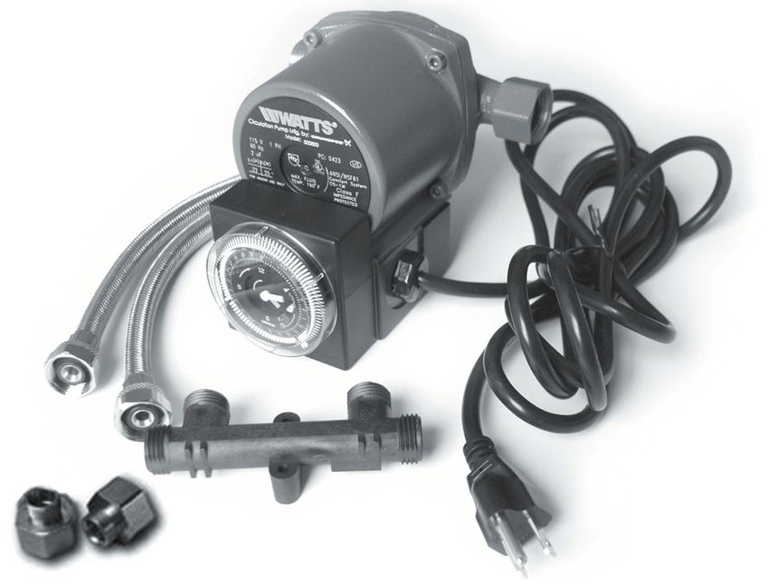
Thank you for your purchase. You are now the owner of a Watts Premier HOT WATER
RECIRCULATION System. It has been carefully inspected and tested before shipment.
It should give you long, efficient, trouble-free service. For maximum performance and
reliability, please follow the simple instructions in this manual.

NOTE: Please understand this is not an anti-scald device. You may have some warm water
in your cold water line under the sink where the valve is installed. Once the cold water line
is opened, the warm water will dissipate in a very short time.
                                                                         Table of Contents
Package Contents ...................................................................................................................................................... 2
Tools Required for Basic Installation ........................................................................................................................... 2
Operational Parameters .............................................................................................................................................. 2
Pump Installation ........................................................................................................................................................ 3
Sensor Valve Installation ............................................................................................................................................ 4
Timer Operation .......................................................................................................................................................... 5
Timer Control Technical Data ..................................................................................................................................... 6
Troubleshooting .......................................................................................................................................................... 6
Warranty ..................................................................................................................................................................... 7

Package Contents
Examine the components carefully to make sure no damage has occurred to the pump. Care should be taken to ensure
the pump is NOT dropped or mishandled; dropping will damage the pump.

Package Contains the following:

             • 1- Hot water recirculator pump with timer
             • 1-Sensor Valve
             • 2- Valve mounting screws
             • 2- 3/8” compression to 1/2” threaded flex hoses
             • 2- adapters
             • 2- rubber washers
             • Installation and Operating Instructions

Tools Required for Basic Installation
(Copper Flex Line / Braided Hose Connections)

             • Adjustable Wrench
             • Towel
             • Drip Pan

Estimated installation time is 20 minutes to 1 hour (dependant on your existing plumbing, hard plumbed
copper may take longer).

Operational Parameters

The maximum allowable water temperature is 150 degrees Fahrenheit for the circulator pump and timer.

                                                                                        Page 2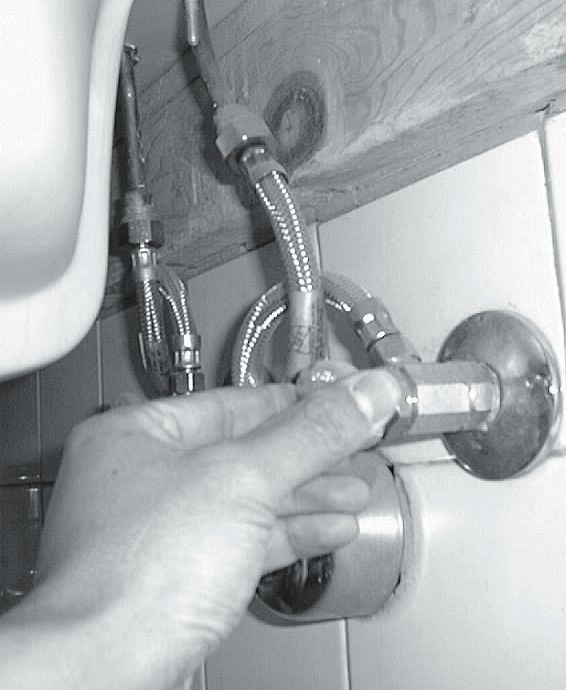
PUMP INSTALLATION
Water Heater Checklist

         Electric Water Heater
                Turn off Power to your Water Heater. (turn off power at breaker box)

     Gas Water Heater
           Turn off the Gas to your water heater and insure that the pilot light is                           DO NOT
                                                                                                            Mount Motor
           not burning.                                                                                    Shaft in Vertical
Pump Mounting: For Indoor Use Only                                                                            Position

1. Close the supply water valve to the water heater located, in most                          Picture 1
cases, above the water heater on the cold water inlet to the hot water
heater.

2. Drain the water from the hot water pipe by opening a hot water faucet
in the house. Let the water run until it stops flowing. Then drain remaining                               Disconnect
water from hot water heater spigot. Leave the faucet in the house open
until pump installation is complete.
NOTE: If water does not stop flowing, check to make sure the water
to the hot water heater has been completely shut off.

3. Disconnect the hot water discharge at the hot water heater.
(see Picture #1)

4. Install pump onto the nipple of the water heater discharge line, using
the 3/4” female fitting and gasket supplied on the pump. Confirm the                            Picture 2
directional flow of water by observing the flow arrow on the
side of the pump housing. The pump should be installed so that
the pump is pumping water away from the hot water heater, towards

                                                                                                                  Direction of Water
the house (See Picture #2). Be sure that the pump is not touching the
exhaust vent piping (chimney) of a gas or oil fired hot water heater.
5. Connect the gasketed flexible copper hot water line to the 3/4” NPT
discharge of the pump.
NOTE: When using a gasketed flexible copper water heater
connector, pipe dope or Teflon tape is not required.
6. Reopen the supply valve to the hot water heater and allow the water to
run until all the air has been purged from the piping.

7. Close faucet inside the house.
8. Plug the line cord of pump into a 115V outlet. Be sure to route the power cord so that it does not
touch the exhaust vent piping of a gas or oil fired hot water heater.
NOTE: The use of an extension cord is not recommended.
ELECTRICAL SAFETY WARNING
Warning - Risk of electrical shock - This pump is supplied with a grounding conductor. To reduce the risk of
electric shock, be certain that it is connected only to a properly grounded grounding type receptacle. The safe
operation of this pump requires that it be grounded in accordance with the National Electrical Code and local
governing codes and regulations.
Electrical Requirements
The operating voltage and other electrical data are marked on the motor label. Make sure that the motor is suitable for the
electrical supply on which it will be used.
Electrical Connection
Insert the 115V plug on the line cord from the pump into a properly grounded 115V outlet.

                                                          Page 3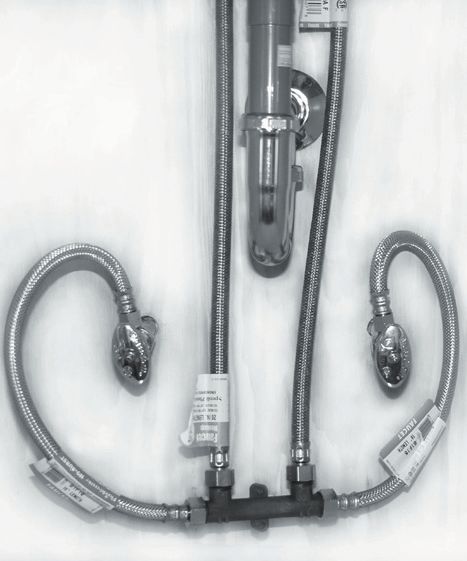
Sensor Valve Installation
Sensor Valve Location

For the optimal performance, the valve should be located at a faucet with the greatest piping
distance from the hot water heater. If your home has a branched hot water line, more than one
Sensor Valve may be necessary. Additional Sensor Valve kits can be found at some retail locations
as well as Watts Premier website at www.wattspremier.com or by calling toll free at (800) 752-5582.

**NOTE: Do Not Use Teflon Tape or Pipe Dope on the Sensor Valve Threads.**
                                                                                   Picture 3
3/8” Stop Valve Installation

   1. Close both the hot and cold stop valves below the sink (see Picture 3).
   2. Place supplied rubber washers in female end of adapters. Attach
      adapters to both the “Cold Out” and “Hot Out” labeled ports on the
      Sensor Valve. Finger tight plus a quarter turn with wrench
      (see Picture 4).
   3. Disconnect existing supply line connection from both hot and cold stop
      valves and then connect to the adapter attached to        Picture 4
      Sensor Valve in step 2. Finger tight plus a quarter turn
      with wrench (see Picture 4).
   4. Connect the new 1/2” x 3/8” flex hose to the hot water
      stop valve (3/8” side) and the “Hot In” port (1/2” side)
      of the Sensor Valve (see Picture 5). Connect the
      remaining 1/2” x 3/8” flex hose to the cold water stop
      valve, finger tight plus a quarter turn with wrench.
   5. Open both the hot water and cold water stop valves.
   6. If desired, Sensor Valve can be mounted to the wall
      with the mounting screws.

1/2” or Other Stop Valve Installation

   1. Close both the hot and cold stop valves below the
      sink (see Picture 3).
   2. Place supplied rubber washers in female end of
      adapters. Attach adapters to both “Cold In” and “Hot
      In” labeled ports on the Sensor Valve. Finger tight
      plus a quarter turn with wrench (see Picture 4).          Picture 5

   3. Disconnect existing supply line connection from faucet
      connection leave stop valve connection in place. Take
      disconected end and attach to “Hot Out” and “Cold
      Out” connections respectively
   4. Connect the new 1/2” x 3/8” flex hose to the already
      installed adapter (on Sensor Valve) (3/8” side) and the
      faucet connection (1/2” side) for both Hot Water and
      Cold Water respectively (see Picture 5).
   5. Open both the hot water and cold water stop valves.
   6. If desired, Sensor Valve can be mounted to the wall
      with the mounting screws.                                        Hot Water                 Cold
                                                                          Out                  Water Out

                                                                  Hot Water                        Cold
                                               Page 4                 In                          Water In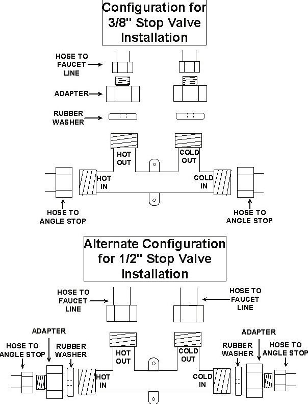
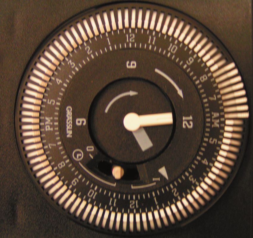
TIMER OPERATION
Use the timer to set the pump to operate around your peak use times. (ie. 30 minutes before the first
shower until 15 minutes after last shower).

NOTE: Before the circulator is started, the water system must be filled with water and purged of air.

                               Mode Switch

Time Setting
NOTE: REMOVE OUTER PLASTIC COVER: DO NOT SET THE TIME BY ROTATING “OUTER” DIAL.

TO SET THE CURRENT TIME, TURN THE MINUTE HAND CLOCKWISE.

Turn the minute hand clockwise until the current time of day on the outer dial is aligned with the triangle marker on the
inner dial (two o’clock position on the inner dial). Example for 2:00 AM is pictured above.

Programming
Setting the 24-Hour Dial
The 24-Hour dial has quarter-hour divisions and AM/PM indications. The time switch is programmed by pushing the
captive trippers to the outer ring position for the entire period that the load is to be turned “ON”, i.e., fifteen minutes for
each tripper on the 24-Hour dial. When the tripper is pushed to the inside, the switch is in the “OFF” position (the picture
above shows the timer set for 6:00 AM to 8:00 AM).

The timer is also equipped with a 3 positional mode switch.
• Moving the switch to the left (towards the “O”) activates “OFF” mode, which turns the pumps off.
• Moving the switch to the middle position activates the “TIMER” function, where the pump turns on or off
   according to the programmed intervals.
• Moving the switch to the right (towards the “I”) activates “ON” mode, where the pump will run constantly
   without shutting off.
Note: It is recommended to run this switch in the “TIMER” (middle) position (as shown in the picture
above).

                                                            Page 5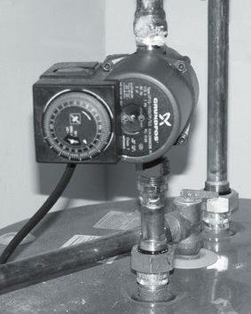
TIMER CONTROL TECHNICAL DATA

Supply Voltage: 120 VAC, 60Hz

Temp. Range: –40°F to 180°F

Shortest Switching Interval: 15 minute increment
Switch Modes: “Timer”, “ON” Override, “OFF”Override
Protection: Clear plastic cover for dust and moisture protection of the clock face.

Timer Technical Application
The timer control is designed only for use with the specified WATTS INSTANT HOT WATER RECIRCULATING
SYSTEM Water system (#500800). Installed indoors on hot water service systems.

The timer control is designed to turn the circulator on and off at preset times, allowing the user to select operation of the
circulator during high use periods of the day.

Troubleshooting
If there appears to be too much hot water on the cold water side the following steps will determine if the valve is
operating correctly:

1. Close the cold water stop valve below the sink.

2. Open the cold water faucet.

3. Water should slowly flow from the faucet until hot water reaches the valve.
   The flow should gradually decrease until no water is coming from the faucet
   at which time the valve is closed.

                                                            Page 6
Limited Warranty
What your Warranty Covers:
If any part of your WATTS INSTANT HOT WATER RECIRCULATING SYSTEM is defective in workmanship,
return unit after obtaining a return authorization (see below), less tank, within 12 months of original retail
purchase, WATTS will repair or, at WATT’S option, replace the unit.
How to obtain Warranty Service:
For warranty service, call 1-800-752-5582 for a return authorization number. Then, ship your unit to our
factory, freight and insurance prepaid, with proof of date of original purchase. Please include a note stating
the problem. WATTS PREMIER will repair it, or replace it, and ship it back to you prepaid.
What this warranty does not cover:
This warranty does not cover defects resulting from improper installation, (contrary to WATTS PREMIER’s
printed instructions), from abuse, misuse, misapplication, improper maintenance, neglect, alteration,
accidents, casualties, fire, flood, freezing, environmental factors, water pressure spikes or other such acts
of God.
This warranty will be void if defects occur due to failure to observe the following conditions:
1. The WATTS INSTANT HOT WATER RECIRCULATING SYSTEM must be hooked up to a potable
municipal or well cold water supply.
This warranty does not cover any equipment that is relocated from the site of its original installation.
This warranty does not cover any equipment that is installed or used outside the United States of America
and Canada.
LIMITATIONS AND EXCLUSIONS:
WATTS WILL NOT BE RESPONSIBLE FOR ANY IMPLIED WARRANTIES, INCLUDING THOSE OF
MERCHANTABILITY AND FITNESS FOR A PARTICULAR PURPOSE. WATTS WILL NOT BE RESPONSIBLE
FOR ANY INCIDENTAL OR CONSEQUENTIAL DAMAGES, INCLUDING TRAVEL EXPENSE, TELEPHONE
CHARGES, LOSS OF REVENUE, LOSS OF TIME, INCONVENIENCE, LOSS OF USE OF THE EQUIPMENT,
AND DAMAGE CAUSED BY THIS EQUIPMENT AND ITS FAILURE TO FUNCTION PROPERLY. THIS
WARRANTY SETS FORTH ALL OF WATT’S RESPONSIBILITIES REGARDING THIS EQUIPMENT.
YOUR RIGHTS UNDER STATE LAW:
Some states do not allow limitations on how long an implied warranty lasts, and some states do not allow
the exclusion or limitation of incidental or consequential damages, so the above limitations or exclusions
may not apply. This warranty gives you specific legal rights, and you may have other legal rights which vary
from state to state.
CALIFORNIA PROPOSITION 65 WARNING
WARNING: This product contains chemicals known to the State of California to cause cancer and birth
defects or other reproductive harm. (California law requires this warning to be given to customers in the
State of California). For more information: www.wattsind.com/prop65Watts Premier, Inc. Phoenix, AZ 85027 Phone: 800-752-5582 www.wattspremier.com Fax: 623-931-0191
You can also read