EPS1200 SERIES ECO-PLUS PORTABLE HAND-WASH STATION - Acorn Engineering
←
→
Page content transcription
If your browser does not render page correctly, please read the page content below
INSTALLATION, OPERATIONS & MAINTENANCE MANUAL
                  Please visit www.acorneng.com
                  for most current specifications.

EPS1200 SERIES
ECO-PLUS PORTABLE HAND-WASH STATION

                                              Comes Ready To Assemble

               EPS1210 - PS1000-F11 - PS1000-PS                      EPS1210 - PS1000-F11 - EPS1200-BS1

            TECHNICAL ASSISTANCE TOLL FREE TELEPHONE NUMBER
                              1.800.743.8259
                               TECHNICAL ASSISTANCE FAX: 1.626.855.4863

   NOTES TO THE INSTALLER:
   1. Please leave this documentation with the owner of the fixture when finished.
   2. Please read this entire booklet before beginning the installation.

                                           LIMITED WARRANTY
                                      UNITED STATES AND CANADA

   Acorn warrants that all of its products are guaranteed against defective material or poor workmanship for
   a period of one year from date of shipment. Acorn’s liability under this warranty shall be discharged by
   replacing without charge F.O.B. City of Industry, California, any goods, or part thereof, which appear to
   the company upon inspection to be of defective material or not of first class workmanship, provided that
   claim is made in writing to the company within reasonable period after receipt of the product. Where
   claims for defects are made, the defective part or parts shall be delivered to the company, prepaid, at City
   of Industry, California for inspection. Acorn will not be liable for the cost repairs, alterations or
   replacement, or for any expense connected therewith made by the owner or his agents, except upon
   written authority from the Acorn City of Industry office. Acorn will not be liable for any damages caused by
   defective materials or poor workmanship, except for replacements, as above provided. Buyer agrees that
   Acorn has made no other warranties either expressed or implied in addition to those above stated, except
   that of title with respect to any of the products or equipment sold hereunder and that Acorn shall not be
   liable for general, special or consequential damages claimed to arise under the contract of sale. All
   designs are subject to change without notice. Unless stated in the order, material will be furnished of the
   design in effect at the time the order is filled.

                                                                            ACORN ENGINEERING FIELD SERVICE
                                                  TOLL FREE 800-743-8259 • LOCAL 626-855-4866 • FAX 626-855-4863
Part #: 6218-000-001                                  Page 1 of 13                                  Rev A: 05/26/2021
INSTALLATION, OPERATIONS & MAINTENANCE MANUAL

TECHNICAL DIMENSIONS

                                   2

                                                          NOTES
                                                          1. RECTANGULAR BOWL
   1                                                      2. OPTIONAL DAISY STRAINER
162"                                                      3. OPTIONAL GOOSENECK FAUCET
[419]                                                     4. OPTIONAL PUMP SOAP DISPENSER
                                                          5. CASTER WHEELS
                                                          6. MANUAL FOOT PUMP

                         6             1

                           35"
                         [889]
                                                                      3

                                                                      4

                                                          3721" STD
                                                            [953]
                                                           31" -JR
                                                            [787]

                                                      5
                                                                                            4"
                                                                                          [102]

                                                            ACORN ENGINEERING FIELD SERVICE
                                  TOLL FREE 800-743-8259 • LOCAL 626-855-4866 • FAX 626-855-4863
Part #: 6218-000-001                   Page 2 of 13                               Rev A: 05/26/2021
INSTALLATION, OPERATIONS & MAINTENANCE MANUAL
ASSEMBLE DECK PANEL TO SIDE AND UPPER PANELS
Remove assembly components and hardware from packaging and ensure that
1 there is no damage to components. Remove plastic protective covering from
relevant components.
Locate the Deck Panel, the Front Upper Panel, Back Upper Panel and Side
Panels.
Secure the Front Upper Panel and Back Upper Panel to the Side Panels using
1/4” Screws (Provided). Orient Side Panels as shown in diagram.
Secure the Deck Panel to the Assembly using 1/4” Hardware (Provided).
DECK PANEL
BACK UPPER
PANEL
1/4” SCREW
1/4”
WASHER 1/4” HARDWARE
(NUT/LOCKWASHER
/WASHER)
FRONT UPPER
PANEL
(IDENTIFIED BY
LOWER FLANGE)
ORIENT SIDE PANELS SUCH
SIDE THAT THESE HOLES ARE
PANELS TOWARD THE FRONT END
ACORN ENGINEERING FIELD SERVICE
TOLL FREE 800-743-8259 • LOCAL 626-855-4866 • FAX 626-855-4863
Part #: 6218-000-001 Page 3 of 13 Rev A: 05/26/2021INSTALLATION, OPERATIONS & MAINTENANCE MANUAL
INSTALL LOWER FRONT PANEL AND FLOOR PANEL
Place assembly on its back.
2 Locate the Front Lower Panel, Floor Panel and 1/4” Screws/Washers.
Secure the Front Lower Panel to the Side Panels using 1/4” Screws/Washers
(Provided).
Align and Install the Floor Panel within the Side Panels.
FRONT LOWER
PANEL
FLOOR PANEL
1/4”
WASHER
1/4” SCREWS
SIDE
PANELS
ACORN ENGINEERING FIELD SERVICE
TOLL FREE 800-743-8259 • LOCAL 626-855-4866 • FAX 626-855-4863
Part #: 6218-000-001 Page 4 of 13 Rev A: 05/26/2021INSTALLATION, OPERATIONS & MAINTENANCE MANUAL
INSTALL CASTERS TO CABINET
Place assembly on its side.
3 Locate the Swivel Casters and 3/8” Hardware (Provided).
Secure the Casters to the Floor Panel using 3/8” Hardware (Provided). The
Locking Casters (Identified by Locking Mechanism) are to be installed at the
front end of the unit, while the Non-Locking Casters are to be installed at the
back end.
3/8”
HARDWARE
FLOOR
PANEL
LOCKING
CASTERS
(FRONT SIDE)
NON-LOCKING
CASTERS
ACORN ENGINEERING FIELD SERVICE
TOLL FREE 800-743-8259 • LOCAL 626-855-4866 • FAX 626-855-4863
Part #: 6218-000-001 Page 5 of 13 Rev A: 05/26/2021INSTALLATION, OPERATIONS & MAINTENANCE MANUAL
INSTALL FOOT PUMP
Place assembly on its side.
4 Locate the Foot Pump Assembly and 1/4” Screws/Washers (Provided).
Secure the Foot Pump Assembly to the Floor Panel using 1/4” Screws/Washers
(Provided).
1/4”
SCREWS
1/4”
WASHER
FLOOR PANEL
60” PE
TUBING FOOT PUMP
ASSEMBLY
42” PE
TUBING
Plug in two separate (42” and 60”) 3/8” OD PE
Tubing into the Foot Pump’s quick connect
ports approximately 7/8” deep. Feed the Tubing
through the Floor Panel’s access hole. Refer to
Push-In Fitting for Foot Pump Installation.
ACORN ENGINEERING FIELD SERVICE
TOLL FREE 800-743-8259 • LOCAL 626-855-4866 • FAX 626-855-4863
Part #: 6218-000-001 Page 6 of 13 Rev A: 05/26/2021INSTALLATION, OPERATIONS & MAINTENANCE MANUAL
PUSH-IN FITTING INSTALLATION FOR 3/8” TUBING TO FOOT PUMP
NOTE: FITTINGS AND TUBE SHOULD BE KEPT
CLEAN, BAGGED AND UNDAMAGED PRIOR TO
INSTALLATION.
TO CUT TUBE:
Cut to fit length of 3/8” PE tubing and remove any burrs
or sharp edges. Ensure that the outside diameter is free
from score marks. Tube ends should be square.
INSERTING THE TUBE:
O-RING
1. Firmly and fully insert the tubing end into the push-in
fitting up to the tube stop located approximately 7/8” O-RING
deep.
COLLET
TUBE STOP
COLLET
2. Pull on the fitted tubing to ensure it is secure. Tube
should not come free from the fitting. Water test the
connection assembly prior to leaving the site to ensure
there are no leaks.
COLLET
COLLET
DISCONNECTING THE TUBE:
To disconnect the tube from the fitting ensure that the
water line is depressurized. Push collet square towards
the push-in fitting body and hold. While holding the collet
in, pull on the PE tubing to remove from the push-in fitting.
COLLET
ACORN ENGINEERING FIELD SERVICE
TOLL FREE 800-743-8259 • LOCAL 626-855-4866 • FAX 626-855-4863
Part #: 6218-000-001 Page 7 of 13 Rev A: 05/26/2021INSTALLATION, OPERATIONS & MAINTENANCE MANUAL
INSERT BASIN WASTE ASSEMBLY
Place the assembly in the upright position.
5 Locate the Drain Assembly.
Remove the Drain Screw and Daisy Strainer from the Drain Assembly, and
ready them above the Rectangular Basin.
Align the Drain Adapter Gasket and Access Drain below the Rectangular Basin,
and Secure the Drain Assembly using the Drain Screw.
Position Waste Water Tank inside Cabinet and assemble Clear Tubing to cap as
shown.
DRAIN
SCREW
DAISY INSTALL FROM
STRAINER INSIDE BASIN
DRAIN ADAPTER
GASKET
BASIN
ACCESS
DRAIN
7/8” SPRING
HOSE CLAMP
WASTE
5/8” ID X 7/8” OD
CLEAR TUBE
ACORN ENGINEERING FIELD SERVICE
TOLL FREE 800-743-8259 • LOCAL 626-855-4866 • FAX 626-855-4863
Part #: 6218-000-001 Page 8 of 13 Rev A: 05/26/2021INSTALLATION, OPERATIONS & MAINTENANCE MANUAL
OPTIONAL FAUCET AND SOAP ASSEMBLY
Place the assembly in the upright position.
6 Locate the Faucet Assembly and Soap Dispenser Assembly.
Remove the Faucet Washer/Nut Hardware and ready the Faucet Spout above
Deck Panel.
Align the Faucet Washer/Nut Hardware below the Deck Panel and Secure the
Faucet Assembly to the Deck Panel.
For optional soap assembly, remove Soap Tank and Washer/Nut Hardware from
Soap Dispenser Assembly and ready Soap Spout above the Deck Panel (It is
recommended to assemble Soap Dispenser Assembly after Step 9).
Align the Soap Tank and Washer/Nut Hardware below the Deck Panel and
Secure the Soap Dispenser Assembly to the Deck Panel. Refer to Install.
FAUCET SOAP
SPOUT SPOUT
DECK
PANEL
FAUCET WASHER/NUT
HARDWARE
SOAP WASHER/NUT
HARDWARE
SOAP TANK
ACORN ENGINEERING FIELD SERVICE
TOLL FREE 800-743-8259 • LOCAL 626-855-4866 • FAX 626-855-4863
Part #: 6218-000-001 Page 9 of 13 Rev A: 05/26/2021INSTALLATION, OPERATIONS & MAINTENANCE MANUAL
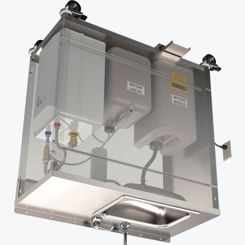
HOT WATER HEATER AND WATER TANK ASSEMBLY
Place the assembly in the upright position.
7 It is recommended to install Water Heater and Fresh Water Tank according to
the following water path (Front View of Fixture).
Use a funnel to fill Water Heater with 4 gallons of fresh water and fill Fresh
Water Tank completely. Refer to Water Heater Set-up Details.
After making necessary water connections, a sufficient electrical receptacle
(Minimum: 110/120V, 12A) will be required to provide power to Water Heater.
NOTE: DO NOT PLUG IN WATER HEATER AT THIS POINT
FAUCET
1 Plug in the 3/8” x 60” OD
PE Tubing from the Foot
Pump (Inward Arrow) into the
3/8” NPT TO Fresh Water Container and
3/8” OD TUBE the 3/8” x 42” OD PE Tubing
ADAPTER
(Outward Arrow) into the T-
Piece. The T-Piece will need
to have the 1/2” to 3/8”
MIXING Reducer and 3/8” NPT to 3/8”
VALVE OD Tube Adapter secured
before plugging in PE Tubing
(It is recommended to use
3 piping tape to ensure a proper
seal). Refer to Push-In Fitting
2 Installation Detail.
BRAIDED
HOSES 2 Connect a 1/2” NPS x 6-
1/2” TO 3/8” 1/4” Braided SS Hose into the
42” PE 60” PE REDUCER
T-Piece and Mixing Valve
TUBING TUBING
1/2” CLOSE (Cold). Connect another 1/2”
H C NIPPLE NPS x 6-1/4” Braided SS
Hose into the T-Piece and
WATER
Water Heater (Cold).
HEATER
3 Connect a 1/2” NPS x 15-
1 3/4” Braided SS Hose into the
FRESH Mixing Valve (Hot) and Water
WATER Heater (Hot). Connect 1/2”
NPS x 24” Braided SS Hose
FOOT into Mixing Valve (Mixed) and
PUMP Faucet.
NOTE: MIXING VALVE IS FACTORY PRESET AT 105 DEGREES FAHRENHEIT
ACORN ENGINEERING FIELD SERVICE
TOLL FREE 800-743-8259 • LOCAL 626-855-4866 • FAX 626-855-4863
Part #: 6218-000-001 Page 10 of 13 Rev A: 05/26/2021INSTALLATION, OPERATIONS & MAINTENANCE MANUAL
INSTALL FRONT ACCESS PANEL
Place the assembly in the upright position.
8 Locate the Front Access Panel and 1/4” Screws/Washers.
Secure the Front Access Panel to the Side Panels using 1/4” Screws/Washers
(Provided).
DECK PANEL
FRONT ACCESS
PANEL
1/4” WASHER
1/4” SCREW
SIDE PANEL
ACORN ENGINEERING FIELD SERVICE
TOLL FREE 800-743-8259 • LOCAL 626-855-4866 • FAX 626-855-4863
Part #: 6218-000-001 Page 11 of 13 Rev A: 05/26/2021INSTALLATION, OPERATIONS & MAINTENANCE MANUAL
WATER HEATER SET-UP
OPEN CLOSED
DETAIL B DETAIL C
OPERATION
DETAIL A Important: Prior to operation ensure all steps to fill and prime the Water Heater
tank have been performed and fresh water tank is full.
1. Fill Water Heater with 4 gallons of fresh water and fill Fresh Water Tank
4 GALLONS completely (DETAIL A).
FRESH WATER 2. Before plugging in Water Heater, open Relief Valve and pump the Foot
Pump until water escapes through the Valve (DETAIL B).
3. Close the Relief Valve and pump Foot Pump until water exits through the
Faucet (DETAIL C). Plug in the Water Heater to an acceptable electrical
receptacle.
4. IMPORTANT!!! Monitor and prevent water reservoir from emptying
H C fully as this will prevent the tank from overheating. If water reservoir
is not immediately refilled, the heater should be unplugged. If the fresh
water reservoir has been drained and refilled and the foot pump does not
pump efficiently it may be necessary to let the tank cool and purge the tank
WATER again by opening the pressure Relief Valve and repeating steps 2-3.
HEATER NOTE: The water heater tank does not pressurize and is always vented
and open to atmosphere through the faucet.
5. Position unit in desired location and ensure Casters are securely locked in
place.
6. Unit is now ready for operation. Depressing foot pump will allow water to
flow from faucet. Flow should stop when foot pump is not being activated.
*IMPORTANT:
Electrical supply will be required from GFCI protected receptacle per Water
Heater Manufacturer instructions. Refer to complete installation instructions
provided by Chronomite® Electric Mini Tank - Water Heaters.
Refer to the Installation Instructions for the model specified:
§ CMT-4.0 (12A, 120V)
For additional information refer to website: www.Chronomite.com
ACORN ENGINEERING FIELD SERVICE
TOLL FREE 800-743-8259 • LOCAL 626-855-4866 • FAX 626-855-4863
Part #: 6218-000-001 Page 12 of 13 Rev A: 05/26/2021INSTALLATION, OPERATIONS & MAINTENANCE MANUAL
CARE AND CLEANING OF
STAINLESS STEEL
SURFACE
NORMAL CLEANING
Clean weekly or more often, as needed
(especially high polishing surfaces)
RECOMMENDED CLEANING MATERIALS
- Sponge – natural or artificial
- Nylon or other soft-bristle material brush
- Soft cloth (as used on automobile finishes)
RECOMMENDED CLEANING SOLUTIONS
- Hand dishwashing liquid/soft water solution
- Mild soap/soft water solution
- 3M Stainless Steel Cleaner/Polish
- White vinegar/soft water solution
(for brightening, removing oil and
hard water deposits)
- CLR Brand Cleanser or baking soda/soft
water solution (for brightening, removing
hard water deposits)
- Club soda and sponge
To remove smudges and fingerprints:
Wipe surfaces with a quality Stainless Steel
Cleaner/Polish. Apply using a soft non-abrasive
cloth, wipe surfaces with stainless steel cleaner/polish.
To remove rust stains:
Wipe surfaces with CRES (available from Acorn) or equivalent cleaner. Use recommended solutions. Apply
using a soft non-abrasive sponge. Rinse surfaces immediately after application. Always follow cleaner product
directions provided. Afterwards, using a soft, non-abrasive cloth, wipe surfaces with stainless steel
cleaner/polish.
FOR TOUGH PROBLEMS
- CRES Cleaner specifically for rust stains (available from Acorn)
- Tarn-X for general stains
- #7 chrome polish
- Silver polish
To remove stubborn spots or to treat a scratch (Standard Satin Finish Only):
Use of synthetic, abrasive, general-purpose pads such as Scotch Brite is recommended.
Apply the stainless steel cleaner/polish to the synthetic, abrasive pads and CAREFULLY rub out spot with
cleaner/ polish. Be sure to rub in the direction of the grain! Do not allow steel wool to come in contact with the
stainless steel. Steel particles can embed into the stainless steel surface and create rust!
Stainless steel should be kept clean at all times. If maintained, stainless steel surfaces will retain their new,
clean, polished appearance indefinitely. To remove water spots or rust spots, stainless steel cleaner/polish on a
cloth is recommended.
IF SPOTS ARE STUBBORN OR IF YOU WISH TO TREAT A SCRATCH: synthetic, abrasive, general-purpose
pads such as Scotch Brite are recommended. Apply the stainless steel cleaner/polish to the synthetic, abrasive
pad and CAREFULLY rub out spot with cleaner/polish. Be sure to rub in the direction of the grain! Do not
allow steel wool to come in contact with stainless steel. Steel particles can embed into the surface.
ACORN ENGINEERING FIELD SERVICE
TOLL FREE 800-743-8259 • LOCAL 626-855-4866 • FAX 626-855-4863
Part #: 6218-000-001 Page 13 of 13 Rev A: 05/26/2021You can also read