USB-to-CAN V2 compact embedded automotive professional USB CAN Interface - Hardware Manual
←
→
Page content transcription
If your browser does not render page correctly, please read the page content below
Hardware Manual

USB-to-CAN V2
                    compact
                    embedded
                    automotive
                    professional

USB CAN Interface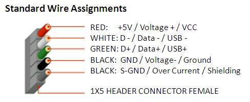
IXXAT Automation GmbH
Leibnizstr. 15
88250 Weingarten
Germany

Tel.: +49 751 56146-0
Fax: +49 751 56146-29
Internet: www.ixxat.com
E-Mail: info@ixxat.com

Support
In case of unsolvable problems with this product or other IXXAT products
please contact IXXAT in written form:

Fax: +49 751 56146-29
E-Mail: support@ixxat.de

Further international support contacts can be found on our webpage
www.ixxat.com

Copyright
Duplication (copying, printing, microfilm or other forms) and the electronic
distribution of this document is only allowed with explicit permission of
IXXAT Automation GmbH. IXXAT Automation GmbH reserves the right to
change technical data without prior announcement. The general business
conditions and the regulations of the license agreement do apply. All
rights are reserved.

Registered trademarks
All trademarks mentioned in this document and where applicable third
party registered are absolutely subject to the conditions of each valid
label right and the rights of particular registered proprietor. The absence
of identification of a trademark does not automatically mean that it is not
protected by trademark law.

Document number: 4.01.0280.20000
Version: 1.1
Content

1   Introduction .................................................................................... 5
2   Installation ...................................................................................... 6
    2.1 Software installation ............................................................... 6
    2.2 Hardware installation .............................................................. 6
          2.2.1 USB-to-CANV2 compact / professional / automotive ................ 6
          2.2.2 USB-to-CANV2 embedded ........................................................ 6
3   Connectors and displays .............................................................. 7
    3.1 USB connector ........................................................................ 7
    3.2 Fieldbus connector ................................................................. 7
          3.2.1 USB-to-CANV2 compact / embedded ...................................... 7
          3.2.2 USB-to-CANV2 professional ..................................................... 8
          3.2.3 USB-to-CANV2 automotive ....................................................... 8
    3.3 Displays ................................................................................... 9
          3.3.1    USB LED .................................................................................. 9
          3.3.2    CAN LED.................................................................................. 9
          3.3.3    CAN1 LS LED ........................................................................ 10
          3.3.4    LIN LED.................................................................................. 10
4   Notes ............................................................................................. 11
    4.1 CAN bus termination ............................................................ 11
    4.2 LIN interface .......................................................................... 11
    4.3 USB-to-CANV2 embedded cable wire assignment .............. 11
5   Appendix ...................................................................................... 12
    5.1 Technical data ....................................................................... 12
    5.2 Support .................................................................................. 13
    5.3 Returning hardware .............................................................. 13
    5.4 FCC Compliance ................................................................... 13
    5.5 Disposing of old equipment ................................................. 14
    5.6 Information on EMC .............................................................. 14
    5.7 EC Declaration of Conformity .............................................. 14

                                                                                            V2
Copyright IXXAT Automation GmbH                     3                        USB-to-CAN          Manual, V1.1
Introduction
1 Introduction
By purchasing the IXXAT USB-to-CANV2 interface, you decided for a high-
quality electronic component developed and manufactured according to the
latest technological standards.
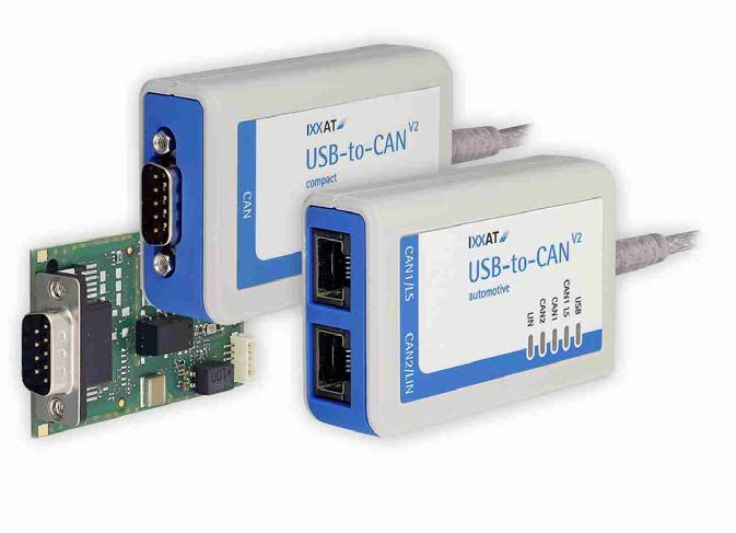
This manual describes the USB-to-CANV2 compact, USB-to-CANV2 embedded,
USB-to-CANV2 professional as well as the USB-to-CANV2 automotive CAN in-
terface.
In the further description these interfaces are referred as CAN-interface.
The properties of the CAN interfaces are:
USB-to-CANV2 compact / embedded
USB 2.0 Hi-Speed (480MBit/s)
one CAN-High-Speed channel according ISO11898-2
optional galvanic CAN bus isolation
fieldbus connection:
o compact: Sub-D9M or RJ45
o embedded: Sub-D9M
USB-to-CAN V2 professional
USB 2.0 Hi-Speed (480MBit/s)
two CAN-High-Speed channels according ISO11898-2
galvanic CAN bus isolation (both CAN channels are on the same potential)
fieldbus connection: 2 x RJ45
equipped with two cable adapter RJ45 to Sub-D9M
USB-to-CAN V2 automotive
USB 2.0 Hi-Speed (480MBit/s)
two CAN-High-Speed channels according ISO11898-2, CAN1 can be
switched between high- and low-speed (ISO 11898-3) via software.
one LIN-Interface V1.3, Master/Slave-Mode switchable via software.
Please refer to the instructions in chapter 4.2
galvanic fieldbus isolation (all field bus channels are on the same potential)
fieldbus connection: 2 x RJ45
equipped with two cable adapter RJ45 to Sub-D9M
V2
Copyright IXXAT Automation GmbH 5 USB-to-CAN Manual, V1.1Installation
2 Installation
2.1 Software installation
To operate the interface a driver has to be installed first. For Windows this
driver is part of the VCI (Virtual CAN Interface) V3, which can be downloaded
for free on the IXXAT webpage http://www.ixxat.com.
For installation of the VCI V3 driver on Windows comuters, please refer to the
VCI installation manual.
IXXAT also offers the ECI driver for Linux and real-time operating systems for
many CAN interfaces. Information on supported operating systems and inter-
faces is available on the IXXAT webpage http://www.ixxat.com.
2.2 Hardware installation
Before connecting the CAN interface to the USB socket on your PC, you
should install the software driver first(see previous section).
2.2.1 USB-to-CANV2 compact / professional / automotive
The CAN-Interface can be connected on the fly (hot plug support).
2.2.2 USB-to-CANV2 embedded
For all work on the PC and interface, you must be statically discharged. Work
must be carried out on an earthed, anti-static work mat.
Take the following steps in sequence:
(1) Switch off the PC and unplug the power cord.
(2) Open the PC according to the instructions of the PC manufacturer
and find a suitable slot. The cable for the internal USB connection is de-
signed according to standard USB plugs (see chapter 4.3). Please note
the polarity and the occupancy of the pin connector in your PC. Do not
use force when plugging in.
(3) Make sure that the interface sits tightly in the PC.
(4) Close the PC; the hardware installation is now complete.
V2
Copyright IXXAT Automation GmbH 6 USB-to-CAN Manual, V1.1Connectors and displays
3 Connectors and displays
3.1 USB connector
The shield of the USB cable is connected to ground using a 100nF capacitor
and therefore also connected to ground of the USB plug.
It is recommended, that the interface is directly connected to PC USB ports or
to self powered USB hubs to ensure sufficient power supply.
USB-to-CANV2 compact / professional / automotive
The USB-cable has a plug type "A". The assignment corresponds to the
USB 2.0 standard.
USB-to-CANV2 embedded
The USB-cable has a 5-pin female connector. The assignment corre-
sponds to PC standard for internal USB devices (see chapter 4.3).
3.2 Fieldbus connector
The assignment of the fieldbus connectors (Sub-D9 and RJ45) is in accord-
ance to CiA 303-1.
The shield of the CAN connector is connected to CAN ground via a 1 MΩ re-
sistor and a 10 nF capacitor. The shields of the CAN connectors of the var-
iants USB-to-CANV2 professional and USB-to-CANV2 automotive are connect-
ed directly together.
For non galvanic decoupled CAN interfaces, fieldbus ground and PC ground
are at the same potential.
For best noise immunity, the shields of the CAN cables must directly connect-
ed to ground.
The pin assignment of the connectors CAN interfaces are shown below.
3.2.1 USB-to-CANV2 compact / embedded
Pin No.
Signal Sub-D9 RJ45
CAN-High 7 1
CAN-Low 2 2
GND 3,6 3, 7
V2
Copyright IXXAT Automation GmbH 7 USB-to-CAN Manual, V1.1Connectors and displays
3.2.2 USB-to-CANV2 professional
RJ45, Pin No. Adapter cable
1.01.0074.01000
Signal CAN 1 CAN 2 Sub-D9M, Pin No.
CAN-High 1 1 7
CAN-Low 2 2 2
GND 3,7 3, 7 3, 6
Two RJ45 to Sub-D9M adapter cable will be delivered with the USB-to-CANV2
professional. The cable can be ordered separately too using order number
1.04.0074.0100.
3.2.3 USB-to-CANV2 automotive
RJ45, Pin No. Adapter cable
1.01.0074.01000
Signal CAN 1 CAN 2 Sub-D9M, Pin No.
CAN-High 1 1 7
CAN-Low 2 2 2
GND 3,7 3, 7 3, 6
CAN-High LS 4 - 4
CAN-Low LS 5 - 1
LIN - 6 5
VBATLIN 1 - 8 9
Two RJ45 to Sub-D9M adapter cable will be delivered with the USB-to-CANV2
automotive. The cable can be ordered separately too using order number
1.04.0074.0100.
Picture 3-1: adapter cable RJ45 / Sub-D9M 1.04.0074.01000
1
see chapter 4.2
V2
Copyright IXXAT Automation GmbH 8 USB-to-CAN Manual, V1.1Connectors and displays
3.3 Displays
The CAN-Interfaces have LED´s that shows the current communication status
of USB and fieldbus activities and are labeled with the appropriate name.
3.3.1 USB LED
Light Description Causes / Hints
pattern
off No communication via USB • Device not properly initialized, maybe
the USB port can´t provide enough
power.
• Device not connected to USB port
green USB communication pos- • Device ready for action
sible
red flash State change • Change power state
power saving active
3.3.2 CAN LED
Light Description Causes / Hints
pattern
off No CAN communication • No CAN communication.
• Device not connected to CAN
green/ CAN communication • With each CAN message the LED is
green triggered
flash
red blink- CAN communication, • The CAN controller is in "Error Warning"
ing CAN controller in error of "Error passive" state. CAN communi-
state cation is further possible.
red Bus Off • The CAN controller is in "Bus Off" state.
No CAN communication possible
V2
Copyright IXXAT Automation GmbH 9 USB-to-CAN Manual, V1.1Connectors and displays
3.3.3 CAN1 LS LED
CAN-Low Speed functionality according to ISO11898-3 is only available on
USB-to-CANV2 automotive.
Light Description Causes / Hints
pattern
off CAN High-Speed • CAN high speed interface is activated
transceiver active
orange CAN low speed (fault • CAN low speed interface activated
tolerant) transceiver active
The communication status is shown on CAN1-LED (see chapter 3.3.2)
3.3.4 LIN LED
LIN functionality is only available on USB-to-CANV2 automotive.
Light Description Causes / Hints
pattern
off No LIN • No LIN communication on the LIN bus
communication • Device not connected LIN bus
green/gre LIN communication • With each LIN message the LED is trig-
en flash gered
red/red LIN communication with • On transmission or reception of a LIN
flash errors message an error was detected
V2
Copyright IXXAT Automation GmbH 10 USB-to-CAN Manual, V1.1Notes
4 Notes
4.1 CAN bus termination
There is no bus termination resistor for the CAN bus in the CAN interface inte-
grated. IXXAT offers a bus termination resistor as a feed through connector as
accessory (order number 1.04.0075.03000)
Picture 4-1: CAN bus termination resistor 1.04.0075.03000
4.2 LIN interface
A LIN interface is only available on the USB-to-CANV2 automotive.
The LIN interface can be configured as LIN Master according to LIN specifica-
tion V1.3.
If the CAN interface is used as a LIN-Master, a voltage of 12 V DC (voltage
range 8 - 18 V DC) has to be connected to pin VBATLIN, see chapter 0
Power consumption is limited by a 1 kΩ resistor.
4.3 USB-to-CANV2 embedded cable wire assignment
V2
Copyright IXXAT Automation GmbH 11 USB-to-CAN Manual, V1.1Appendix
5 Appendix
5.1 Technical data
USB-Interface USB 2.0, Hi-Speed (480 MBit/s)
Microcontroller / RAM / Flash: 32 Bit / 192 kByte / 512 kByte
CAN High Speed , ISO 11898-2
CAN bitrates: 10 kbit/s - 1 Mbit/s
CAN transceiver: TI SN65HVD251
CAN bus termination: none
CAN Low Speed , ISO 11898-3
CAN bitrates: 10 kbit/s – 125 kbit/s
CAN transceiver: NXP TJA1054
CAN bus termination low speed, RTH=RTL=4,7kΩ
LIN transceiver: NXP TJA1020
LIN bitrate: max. 20 kbit/s
LIN VBATLIN: 8 - 18V DC, 12 V DC typical
Galvanic field bus isolation: 800 V DC / 500 V AC for 1 min.
Power supply: via USB, 5 V DC / 300 mA
Enclosure material: ABS plastic
Dimension: 80 x 50 x 22 mm
Weight: approx. 100 g
Operating temperature range: -20°C - +70°C
Storage temperature range: -40°C - +85°C
Relative humidity: 10 - 95%, non condensing
Protection class: IP40
V2
Copyright IXXAT Automation GmbH 12 USB-to-CAN Manual, V1.1Appendix
5.2 Support
For more information on our products, FAQ lists and installation tips, please
refer to the support area on our homepage (http://www.ixxat.com). There you
will also find information on current product versions and available updates.
5.3 Returning hardware
If it is necessary to return hardware to us, please download the relevant RMA
form from our homepage and follow the instructions on this form.
5.4 FCC Compliance
Declaration of conformity
This device complies with Part 15 of the FCC Rules. Operation is subject to
the following two conditions: (1) This device may not cause harmful interfer-
ence, and (2) this device must accept any interference received, including in-
terference that may cause undesired operation.
Product Name: USB-to-CAN V2
Model: compact/professional/automotive/embedded
Responsible Party Name: HMS Industrial Networks Inc
Address: 35 E. Wacker Dr, Suite 1700
Chicago , IL 60601
Phone: +1 312 829 0601
Class B digital device – Instructions
This equipment has been tested and found to comply with the limits for a
Class B digital device, pursuant to Part 15 of the FCC rules. These limits
are designed to provide reasonable protection against harmful interfer-
ence in a residential installation. This equipment generates, uses and
can radiate radio frequency energy and, if not installed and used in ac-
cordance with the instructions, may cause harmful interference to radio
communications. However, there is no guarantee that interference will
not occur in a particular installation. If this equipment does cause harm-
ful interference to radio or television reception, which can be determined
by turning the equipment off and on, the user is encouraged to try to cor-
rect the interference by one or more of the following measures:
• Reorient or relocate the receiving antenna.
• Increase the separation between the equipment and the receiver.
• Connect the equipment into an outlet on a circuit different from that to
which the receiver is connected.
• Consult the dealer or an experienced radio/TV technician for help.
V2
Copyright IXXAT Automation GmbH 13 USB-to-CAN Manual, V1.1Appendix
• Changes and Modifications not expressly approved by the manufac-
turer or registrant of this equipment can void your authority to operate
this equipment under FCC rules.
• In order to maintain compliance with FCC regulations shielded cables
must be used with this equipment. Operation with non-approved
equipment or unshielded cables is likely to result in interference to
radio & television reception.
5.5 Disposing of old equipment
This product is covered by ElektroG (WEEE) and has to be disposed accord-
ing to ElektroG (WEEE) separately. Products of IXXAT, which are covered by
ElektroG, are exclusively for commercial use and marked with the symbol of
the crossed-out garbage can.
According to the B2B regulations, the disposal in accordance with § 10 para. 2
clause 3 Electrical and Electronic Equipment act in the version of 16.03.2005
is regulated separately in the General Terms and Conditions and its supple-
ments of IXXAT. The terms and conditions, its supplements and other infor-
mation on disposal of old equipment can be downloaded at www.ixxat.com.
5.6 Information on EMC
The product is a class B device. If the product is used in office or home envi-
ronment radio interference can occur under certain conditions. To ensure fault-
less operation of the device, the following instructions must be followed due to
technical requirements of EMC:
use only the included accessories
the shield of the interfaces must be connected with the device plug and with
the plug on the other side
5.7 EC Declaration of Conformity
EMC compliance testing has been conducted to the Electromagnetic Compati-
bility Directive 2004/108/EC. For more information please consult the EMC
compliance document on the support pages on IXXAT website.
V2
Copyright IXXAT Automation GmbH 14 USB-to-CAN Manual, V1.1You can also read