Solar PV Shade Evaluation Procedure - A method to determine Shade Factor - MCS Certified
←
→
Page content transcription
If your browser does not render page correctly, please read the page content below
GUIDANCE DOCUMENT
                                                                                      MGD 005 ISSUE 1.0 DRAFT

Solar PV Shade Evaluation Procedure

A method to determine Shade Factor

This Standard is the property of MCS Charitable Foundation, The Innovation Centre, Sci-Tech Daresbury, Keckwick Lane,
Cheshire WA4 4FS. Registered Charity No. 1165752
                                        COPYRIGHT © The MCS Charitable Foundation 2019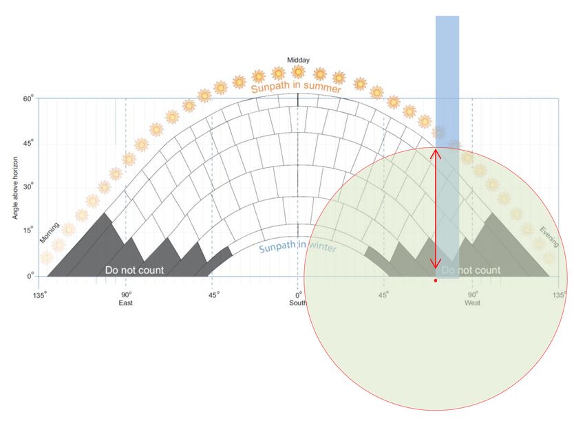
1   This document was prepared by the MCS Working Group 2: Solar PV Systems.

 2   It is published by The MCS Service Company Ltd.

 3   Whilst all reasonable care has been taken in the preparation of this document it is provided on
 4   an “as is” basis without any guarantee of completeness or accuracy. The MCS Service Company
 5   Ltd and The MCS Charitable Foundation (and any related parties) do not accept liability for any
 6   errors or omissions in the document nor for the use or application of the information contained
 7   in the document by any third party.

 8   The MCS Service Company Ltd welcomes comments of a technical or editorial nature and
 9   these should be sent to meetings@mcscertified.com

10   COPYRIGHT © The MCS Charitable Foundation 2020

11   This document is freely available for personal use. Any unauthorised reproduction, use or
12   transmission of all or part of this document without permission is strictly prohibited.

13
14   The MCS Service Company Ltd
15   Innovation Centre,
16   Sci-Tech Daresbury,
17   Keckwick Lane,
18   Cheshire WA4 4FS
19
20   www.mcscertified.com
21   hello@mcscertified.com
22   0333 103 8130
23

       Issue: 1.0                                                                         MGD 005
                                 COPYRIGHT © The MCS Charitable
       Date: XX/XX/2020                Foundation 2020                                   Page 2 of 11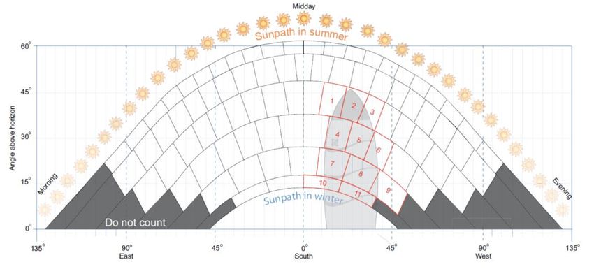
24   ABOUT MCS

25              Giving you confidence in home-grown energy
26   With energy costs constantly rising and climate change affecting us all, low-carbon technology
27   has a bigger and bigger role to play in the future of UK energy.

28   We’re here to ensure it’s a positive one.

29   Working with industry we define, maintain and improve quality – certifying products and
30   installers so people can have confidence in the low-carbon technology they invest in. From
31   solar and wind, to heat pumps, biomass and battery storage, we want to inspire a new
32   generation of home-grown energy, fit for the needs of every UK home and community.

33   About

34   The Microgeneration Certification Scheme Service Company Ltd (MCSSCo Ltd) trades as
35   MCS and is wholly owned by the non-profit MCS Charitable Foundation. Since 2007, MCS has
36   become the recognised Standard for UK products and their installation in the small-scale
37   renewables sector.

38   We create and maintain standards that allow for the certification of products, installers and
39   their installations. Associated with these standards is the certification scheme, run on behalf of
40   MCS by Certification Bodies who hold UKAS accreditation to ISO 17065.

41   MCS certifies low-carbon products and installations used to produce electricity and heat from
42   renewable sources. It is a mark of quality. Membership of MCS demonstrates adherence to
43   these recognised industry standards; highlighting quality, competency and compliance.

44   Vision

45   To see MCS certified products and installations in every UK home and community.

46   Mission

47   To give people confidence in low-carbon energy technology by defining, maintaining and
48   improving quality.

49   Values

50       1.    We are expert – ensuring quality through robust technical knowledge
51       2.    We are inspiring – helping to reshape energy in UK homes and communities
52       3.    We are collaborative – working with industry and government to create positive change
53       4.    We are principled – operating in a way that’s clear, open and fair
54       5.    We are determined – supporting the UK’s drive towards a clean energy future

       Issue: 1.0                                                                           MGD 005
                                   COPYRIGHT © The MCS Charitable
       Date: XX/XX/2020                  Foundation 2020                                   Page 3 of 11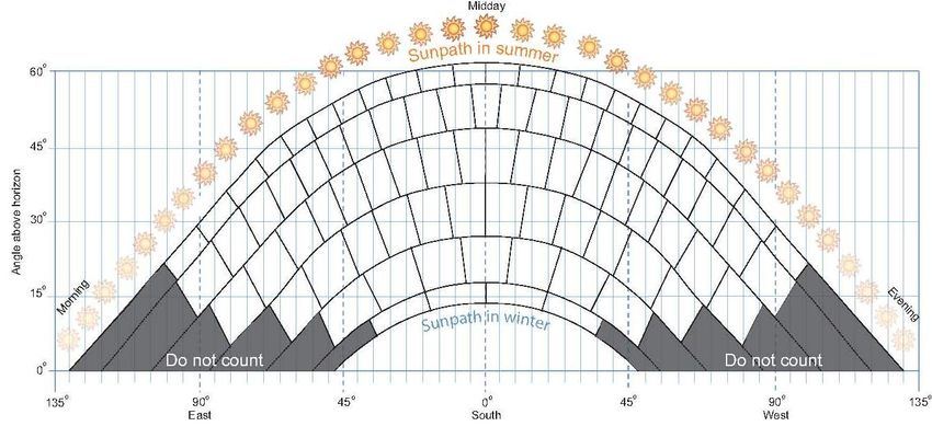
55   TABLE OF CONTENTS
56   Solar PV Shade Evaluation Procedure ..................................................................................................................... 1
57   About MCS ........................................................................................................................................................................... 3
58   Table of Contents .............................................................................................................................................................. 4
59   1         Introduction & Purpose ........................................................................................................................................ 5
60   2         Shade Evaluation Procedure ............................................................................................................................. 6
61       2.1       Objects further than 10m ............................................................................................................................... 6
62       2.2 Objects at, or less than, 10m ......................................................................................................................... 8
63   Appendix A – Shade assessment tools .................................................................................................................. 10
64   Appendix B – Sunpath Diagram .................................................................................................................................. 11

65

         Issue: 1.0                                                                                                                                                      MGD 005
                                                           COPYRIGHT © The MCS Charitable
         Date: XX/XX/2020                                        Foundation 2020                                                                                       Page 4 of 11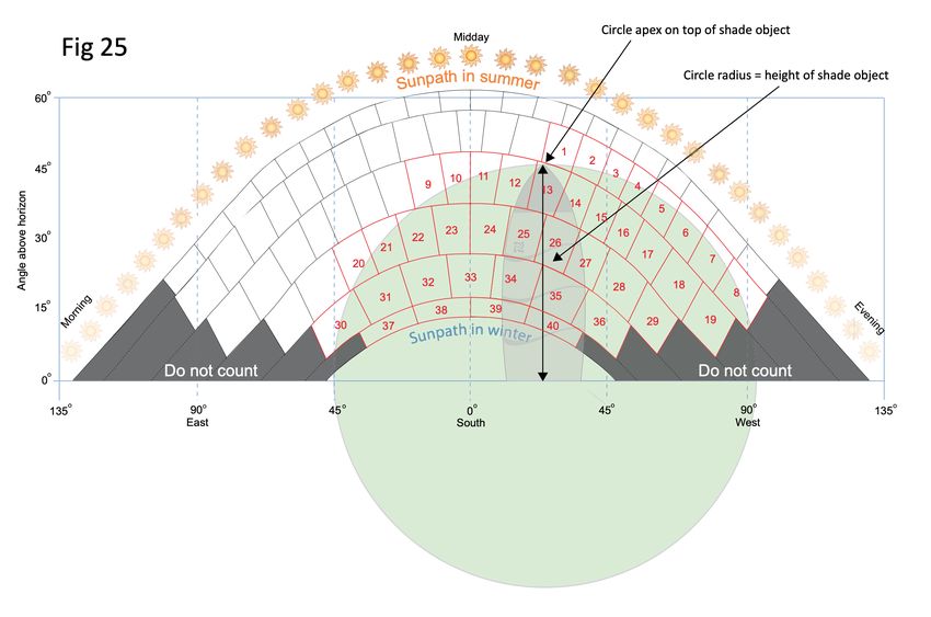
66   1 INTRODUCTION & PURPOSE
67   This is a guidance document. It is neither a mandatory MCS requirement, nor contains
68   mandatory requirements, unless expressly stated as such in an MCS installation standard (MIS)
69   using the words “should” or “shall” in the refence to MGD 005 or its clauses.

70   The purpose of this document is to describe a procedure to assess the potential impact of
71   shading on a solar Photovoltaic array as a result of both near and far objects. The result is a
72   shade factor (SF) which can be used to modify the amount of electricity that it is predicted
73   might be generated by a proposed solar photovoltaic (PV) system.

74   This procedure has been designed to provide a simplified and standardised approach for MCS
75   contractors to use when estimating the impact of shade on system performance. It is not
76   intended to be as accurate as more sophisticated methods such as, for example, those included
77   in proprietary software packages. It is estimated that this shade assessment method will yield
78   results within 10% of the actual annual energy yield for most systems. Unusual systems or
79   environments may produce different results.

80   Where the proposed location for the PV array is subject to significant shading from numerous
81   objects, and making assessment difficult, then installation in that location may simply not be
82   appropriate and the customer should be advised. Near shading especially will have a
83   considerable effect on system performance and should be avoided. Solar PV systems should
84   not be sold where the impact of shade could be severe.

85                                       HEALTH WARNING

86    The method implies the need to undertake assessment at height which can be very
      dangerous. In most cases it should be possible to follow the method without climbing on
87
      roofs provided you can be confident the result is representative.
88
      Where users of this method decide working at height is necessary then all appropriate
89    precautions should be taken to reduce the risk of death or injury from falling.

90

91

       Issue: 1.0                                                                         MGD 005
                                 COPYRIGHT © The MCS Charitable
       Date: XX/XX/2020                Foundation 2020                                   Page 5 of 11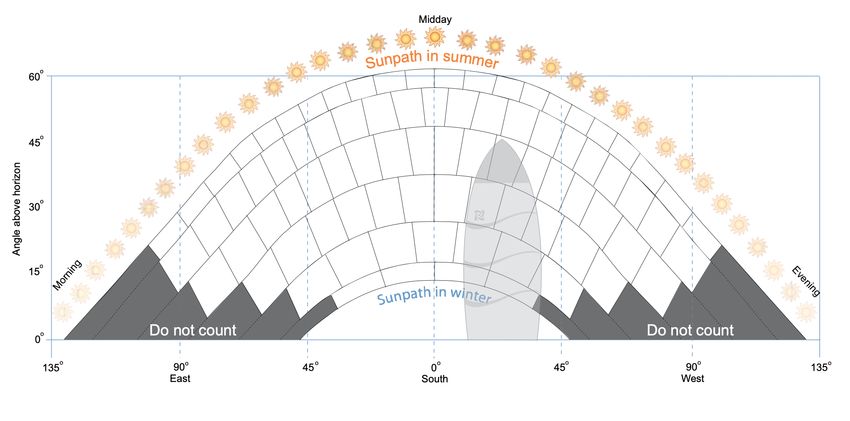
92     2 SHADE EVALUATION PROCEDURE
93     Where there is a potential for shading from objects further than 10m away from the centre
94     midpoint of the array then the procedure given in clause 2.1 shall be used.

95     Where there are objects at or less than 10m away (near shade) from the centre midpoint of the
96     array then the procedure stated in clause 2.2 shall be used.

 97    Assessment shall be undertaken and recorded using the Sunpath chart given in Appendix B to
98     represent the potential irradiance which could be blocked by objects on the horizon at differing
99     times of the day and of the year (as indicated by the different arcs).

100    Note: where manipulating or drawing on the Sunpath chart on a computer it is important the
101    proportions of the chart are not distorted.

102    2.1     OBJECTS FURTHER THAN 10M
103    Principles

104    The chart has a total of 84
105    segments each of which has a
106    value of 0.01.

107    By marking objects on the
108    horizon according to their height
109    and orientation in relation to the
110    proposed array the segments
 111   that are touched are then
                                          Figure 1: Sunpath chart showing segments
112    counted to derive the Shade
113    Factor

114    Location

115    Stand as near as possible to the base and centre of the proposed array, e.g. through an upstairs
116    window, unless there is shading from objects within 10m (e.g. aerials, chimneys, etc.) in which
117    case follow the procedure given later.

118    Tools

119    As a minimum the tools required to undertake this analysis are a compass and a device to
120    measure the elevation of obstacles on the horizon such as an inclinometer.

121    Other more sophisticated tools can be used, and a selection are discussed in Appendix A

122    Detailed Method

         Issue: 1.0                                                                          MGD 005
                                    COPYRIGHT © The MCS Charitable
         Date: XX/XX/2020                 Foundation 2020                                   Page 6 of 11
123 Looking due South (irrespective
124 of the orientation of the array),
125 draw a line showing the
126 uppermost edge of any objects
127 that are visible on the horizon
128 (either near or far) onto the
129 Sunpath chart.
130 This line is called the “horizon
131 line”, an example of which is Figure 2: Sunpath Chart with object on the horizon
132 shown here:
133 Once the horizon line has been drawn, the number of segments that have been touched by the
134 line, or that fall under the horizon line shall be counted, in the following example you can see
135 there are 11 segments covered or touched by the horizon line.
136
137
138 Figure 3: Sunpath chart showing segments affected and counted
139 In Figure 3 the total number of affected segments is 11. This number is then multiplied by their
140 value for each segment (0.01) and the total deducted from 1 to arrive at the Shading Factor (SF)
141 for the proposed installation. In this example the shading factor is calculated as follows:
142 1 - (11*0.01) = 1 – 0.11 = 0.89
143 Notes:
144 Printing the Sunpath chart onto paper to hold at arm’s length and sketching the horizon will
145 not produce a valid result.
Issue: 1.0 MGD 005
COPYRIGHT © The MCS Charitable
Date: XX/XX/2020 Foundation 2020 Page 7 of 11146 For systems connected to module level optimisers, multiple inverters, or a single inverter with
147 multiple independent maximum power-point trackers (MPPT), it is acceptable to do a separate
148 calculation of SF for each sub array (each array connected to a dedicated MPPT).
149 2.2 OBJECTS AT, OR LESS THAN, 10M
150 Principles
151 Shading from objects close to the array (for example: vent pipes, chimneys, and satellite dishes
152 located to the East, South, or West) can have a very significant impact on the performance of
153 PV systems. This is because near objects cast larger shadows, and for more hours of the day,
154 than objects further away. Objects located behind the proposed array (e.g. to the North) do not
155 need to be considered as they will cast little, if any, shadow.
156 To reflect this greater impact the method counts all segments affected within a circle with a
157 radius equal to the height of any object casting a shadow.
158 Where such shading is apparent, it is strongly recommended that either the array should be
159 repositioned away from the objects casting a shadow, or the object(s) casting the shadow
160 should be removed altogether. Then there would be no need to use this method.
161 A further option would to perform a series of calculations and measurements that would allow
162 you to create a chart representative of the shadows cast by objects.
163 Where the installation is still to proceed, and only when all other options have been
164 discounted, then the following method should be used.
165 Location
166 The reading should be taken from the array location worse affected by shade. This will usually
167 mean a location just South of the object casting a shadow.
168 Tools
169 The same tools should be used as described previously. Additionally, a working platform should
170 be erected or, if a roof is to be accessed only with a ladder, then fall arrest equipment should be
171 used.
172 Detailed Method
173 Looking due South, a standard horizon line, as described in clause 2.1, should be drawn onto
174 the Sunpath chart.
175 Objects on the horizon that are 10m or closer to any part of the array, shall have a shade circle
176 added to the chart. Where there are multiple objects within 10m, then multiple circles shall be
177 drawn – one for each object.
Issue: 1.0 MGD 005
COPYRIGHT © The MCS Charitable
Date: XX/XX/2020 Foundation 2020 Page 8 of 11178 The shade circle shall have a radius equal to the height of the object. The shade circle should
179 be located so that the apex of the circle sits on the highest point of the shade object.
180
Figure 4|; Sunpath chart showing near object, circle and segments counted
181
182 If the top of any object extends above the
183 uppermost arc, which represents the
184 Summer path of the Sun, then the apex of
185 the circle should be located at the
186 intersection of the object and that arc.
187 All segments touched by or within the
188 shade circle should be counted as part of
189 the overall shade analysis.
190
Figure 5: Object above the uppermost arc
191
192 In the example shown, using the same shade object as before but now assumed to be nearer
193 than 10m, 40 segments are counted resulting in a shade factor of 0.6 (compared with 0.89
194 before).
Issue: 1.0 MGD 005
COPYRIGHT © The MCS Charitable
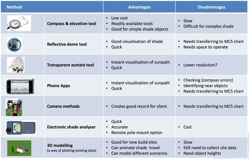
Date: XX/XX/2020 Foundation 2020 Page 9 of 11APPENDIX A – SHADE ASSESSMENT TOOLS
Issue: 1.0 MGD 005
COPYRIGHT © The MCS Charitable
Date: XX/XX/2020 Foundation 2020 Page 10 of 11APPENDIX B – SUNPATH DIAGRAM
Issue: 1.0 MGD 005
COPYRIGHT © The MCS Charitable
Date: XX/XX/2020 Foundation 2020 Page 11 of 11You can also read