LEI guide: ensuring compliant earthing arrangements in PV systems
←
→
Page content transcription
If your browser does not render page correctly, please read the page content below
LEI guide: ensuring compliant
earthing arrangements in PV systems
March 2021

Scope
The objective of this guide is to assist Licensed Electrical Inspectors (LEI) to ensure PV installations are
inspected and tested in accordance with the Electrical Safety Act 1998 and the relevant Australian
Standards. Relating specifically to ensuring compliant earthing arrangements of a PV installation is achieved,
enabling the LEI to certify the PV installation as a compliant electrical installation.
Note: lightening protection earthing systems have not been covered in this document.

Relevant Regulations and Australian Standards
•   Electricity Safety Act 1998
•   Electricity Safety (General) Regulations 2019
•   AS/NZS 3000 Wiring Rules
•   AS/NZS 5033 Installation and safety requirements for photovoltaic (PV) arrays
•   AS/NZS 4777.1 Grid connection of energy systems via inverters – Installation requirement
It is recommended Inspectors consider OH&S processes and safety assessments to ensure the inspection
can be safely completed in accordance with WorkSafe Victoria regulations and requirements.
For more information, refer to the links below:
• ESV - Working safely when installing PV systems
• Safe Work Australia - Safe Work of Roofs Information Sheet

Legislation and requirements
Under the Electricity Safety (General) Regulations 2019, r. 253 states the Obligations of licensed electrical
inspectors;
(1)(a) has attended at the electrical installation address stated on the certificate of compliance and while in
attendance—
        (i) has carried out an inspection of all prescribed electrical installation work described in the
        certificate of compliance in accordance with the Australian/New Zealand Wiring Rules and these
        Regulations; and
        (ii) has carried out testing of all prescribed electrical installation work described in the certificate of
        compliance in accordance the Australian/New Zealand Wiring Rules; and
        (iii) has carried out the tests set out in Division 10 that were required to be carried out on all
        prescribed electrical installation work described in the certificate of compliance;
In PV arrays with a PV array maximum voltage greater than ELV and in systems that include a.c. modules
and micro-inverters with LV outputs, all exposed conductive parts of the PV array shall be earthed.
AS/NZS 5033:2014 Cl. 4.4.2.1
The resistance of an equipotential bonding conductor for exposed conductive parts shall not exceed 0.5 Ω.
AS/NZS 3000:2018 Cl. 8.3.5.2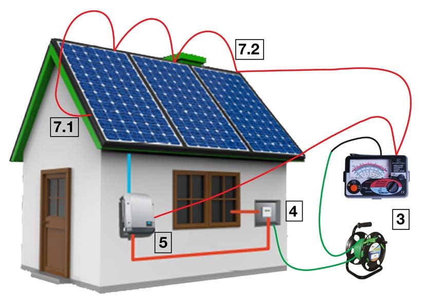
Energy Safe Victoria

Process
Earth continuity testing of a solar installation should be carried out on a de-energised solar
system, as in some unearthed situations, a voltage may be present on the exposed conductive
parts of the solar installation creating a risk of electric shock.
It is recommended Inspectors practise electrical safety protocols to ensure the solar system is
safely isolated and locked out (i.e. using a LOTO kit).

The process of the inspection and testing of the earthing arrangement shall follow the mandatory
requirements set out in AS/NZS 3000:2018 Section 8, Verification.
Section 8 specifies the minimum requirements for the inspection and testing to satisfy the fundamental safety
principles of Part 1 of the Standard in relation to verification of an installation.
Note: Although all sections of AS/NZS 3000 Section 8 shall be followed, this document discusses selected
sections to expand upon and clarify.

Visual inspection - AS/NZS 3000 section 8.2
Verification of the earthing system is a mandatory testing requirement of AS/NZS 3000
Section 8.

Note: A visual inspection would normally be carried out in conjunction with the testing process.
A visual inspection of the PV installation earthing arrangement is to be conducted to verify the following:
1.   The PV array earthing conductor is connected in a compliant manner in the same switchboard or
     distribution board to which the solar inverter is connected, or
2.   The PV array earthing may be connected via the solar inverter. Where not subject to lightning, the
     inverter main earth conductor in the a.c. cable of the inverter output may be used as the earth
     connection point for the PV array, provided that the earthing is arranged such that the removal of the
     inverter for service will not interrupt the earth to the PV array. AS/NZS 5033:2014 Cl.4.4.2.2
3.   The earthing conductor is of the correct type, colour and size. AS/NZS 3000:2018 Cl. 5.3.2
4.   All earthing conductors and earthing mediums shall be installed in a manner that provides adequate
     protection against likely mechanical damage or deterioration. AS/NZS 3000:2018 Cl. 5.5.5
5.   Earthing conductors shall be protected against becoming displaced, damaged or cut by being
     adequately supported by clips, clamps, saddles etc. and protected by a barrier/enclosure where
     appropriate to the expected conditions to prevent mechanical damage. AS/NZS 3000:2018 Cl. 5.5.5.2
6.   Where conductors are exposed to direct sunlight, adequate installations methods must be adopted,
     refer to AS/NZS 3000:2018 Cl.3.3.2.11 Note 1. For insulated unsheathed (single insulated) cables with
     insulation colours other than black, the manufacturer’s recommendations should be sought, or the cable
     should be provided with a physical barrier to prevent exposure to direct sunlight.
7.   Earthing or bonding connections to PV arrays shall be in accordance with AS/NZS 5033:2014 Cl.
     4.4.2.2 (purpose-made fittings), each separate PV array shall be fitted with an earthing connection.
8.   Earthing connections and any fixing devices shall be protected from corrosion AS/NZS 3000:2018 Cl.
     5.5.5.3 (i.e.: painted with Cold Gal).
9.   Joints in mounting rails shall be carried out as per the manufacturer’s instructions and manufacturer rail
     joiners if specified, to ensure continuity of the earthing arrangement throughout the PV array.
10. Penetrating washers layout shall be arranged and in accordance with the manufacturer’s instructions.

LEI Earthing Guide for PV Systems                                                                        Page 2
Energy Safe Victoria

Example of an earthing layout

                              Earth Penetrating Washer                            Earth Lug

              The above diagram is a recommended earthing arrangement as shown in the Clenergy PV-ezRack SolarRoof installation instruction.

11. Ensure penetrating washers are installed correctly, with the penetrating washer dimples securely
    aligned and clamped between the PV module and the rail, or between the earth lug and the rail. A
    misaligned earth washer will compromise the array earthing integrity.

                                                                            A misaligned earthing washer may impede
                                                                            earth continuity.
                                                                            Ensure earth lug and PV Module earthing
                                                                            washers are correctly aligned and securely
                                                                            clamped between the two surfaces.

12. The earthing arrangement shall be arranged so that the removal of one or more PV modules will not
    affect the continuity of the earthing connections to any other PV module. AS/NZS 5033:2014 Cl. 4.4.2.2.

LEI Earthing Guide for PV Systems                                                                                                              Page 3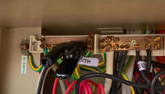
Energy Safe Victoria

Testing – Continuity of the earthing system - AS/NZS 3000 section 8.3.5 Testing
An effective earthing system will ensure exposed conductive parts of electrical equipment do not reach
dangerous voltages when such faults occur.
The resistance of any equipotential bonding conductor or medium shall be not more than 0.5Ω.

Figure 1

Compliant earthing continuity
Verification of the earthing system is a mandatory testing requirement of AS/NZS 3000,
Section 8.

The following is a recommended testing process to verify compliant earthing continuity of a PV installation.
(Refer to Fig. 1 above).
1.   Check and confirm the earth conductors in the switchboard are correctly terminated and connections
     are compliant and tight. All connections throughout the solar installation shall be checked for
     compliance and tightness. (i.e.: ensure all conductor strands are captured, check for terminal tightness,
     and conduct a pull test on the conductor).
2.   Identify and prove an earth reference point (ERP), this may be the main earth conductor or earth bar in
     the switchboard, the metal switchboard enclosure, the main earth electrode, metal water pipe, or nearby
     earth terminal of a socket outlet.
     Note: the ERP must be tested and verified to be below 0.5 Ω when tested to the properties main earth
     conductor.

       TIP 1
       Set yourself up with fittings for multiple test lead arrangement options, such as Banana plugs,
       Alligator clips, Battery clamps for water pipes, test probes for socket outlets etc.

3.   Connect a trailing earth lead and a continuity resistance tester together and zero the tester to
     accommodate the trailing earth lead resistance. (Refer to 3 in Fig.1)

LEI Earthing Guide for PV Systems                                                                        Page 4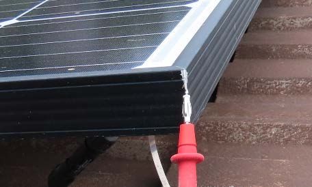
Energy Safe Victoria
4. Connect your trailing lead to your proven ERP. (Refer to 4 in Fig.1)
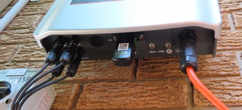
5. Verify the earth continuity to the exposed conductive parts of the solar inverter to the ERP of below
0.5 Ω. (Refer to 5 in Fig.1)
Note: for some inverters the manufacturer may state in the installation instructions; the external earthing
point shall be connected to the earthing system using a screw and lug.
TIP 2
Some Solar inverters may have a plastic or painted surface therefore are non-conductive.
Test your earth continuity to a screw head, often on the underside of the inverter, or the heat
sink at the rear of the inverter.
Ensure the switchboard covers have been replaced to prevent access to any LIVE parts.
Safely access the roof to the PV Array to continue the earth continuity testing.
6. With the trailing earth lead attached to a proven ERP, safely access the PV Array to conduct your earth
continuity testing to ALL exposed parts of the PV array.
7. Verify the exposed conductive parts of the PV array have earth continuity to the proven ERP with a
resistance below 0.5 Ω.
7.1. Test each section of PV mounting rail at the ends, where they have been cut.
TIP 3
PV mounting rails and PV modules are manufactured using anodised aluminium, which
creates an insulated surface. Therefore earth testing should be carried out on a bare cut
section or purpose made earthing point.
LEI Earthing Guide for PV Systems Page 5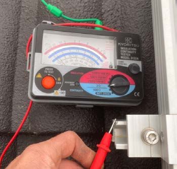
Energy Safe Victoria

                                                With your Insulation Continuity Tester set on
                                                the 3Ω scale, verify the earth continuity is
                                                below 0.5Ω.

     7.2. Test rails throughout the array, ensuring all rail joiners have achieved earth continuity.
     7.3. Test each PV module at the corners where the two cut frames meet, or underneath the panel at the
          manufacturers earthing point.
     Important Note: Aluminium oxidizes when exposed to air. Therefore PV Modules and rails commonly
     have a corrosion-resistant coating. This coating not only provides a protective barrier over the metal, but
     also resists an accurate earth test result. Any exposed edges or corners of the aluminium components
     will oxidize as they are exposed to the elements, this oxidisation on the bare edges may provide a level
     of resistance, therefore affecting the true earth test result.

                                                               Image above showing earthing points at
                                                               the rear of a Hanwha Q Cells PV Module.

     Where an acceptable result cannot be achieved, scratch the corner of the module to remove any build-
     up of oxidisation on the exposed aluminium, then test again by firmly pressing the tip of the test probe
     into the join. (Refer to photo above).
     This will confirm either an adequate earth bond has been achieved, or prove that adequate earthing has
     not been achieved.
     Where accessible, you may also test the earth continuity to the manufacturer’s earthing point on the
     underside of the PV module, (Refer to diagram above).

LEI Earthing Guide for PV Systems                                                                        Page 6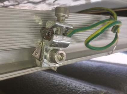
Energy Safe Victoria
Note: All PV modules where accessible shall be tested to ensure compliance to the Electricity Safety
(General) Regulations 2019, AS/NZS 5033 and AS/NZS 3000.
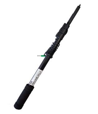
TIP 4
An earth extension probe is handy to reach PV modules in difficult locations.
Has your Prescribed Inspection of the PV system deemed it:
Compliant?
By certifying compliance in the Certificate of Inspection section of the Certificate of Electrical Safety, as the
inspector you are declaring:
I, the Licensed Electrical Inspector, have inspected the prescribed electrical installation work
described in the certificate of compliance and certify the work complies with the Electricity Safety Act
1998 and the Electricity Safety (General) Regulations 2019 (ES(G)R 2019).
If you have identified any defects during your inspection that required rectification before you certified the
certificate as compliant, you must record the defects on the Certificate of Electrical Safety (COES) in
accordance with r.260 of the ES(G)R 2019.
Non-compliant?
If your inspection deems the PV system as non-compliant, and the identified defects cannot be immediately
rectified by the installer, the LEI is to certify the Certificate of Inspection section of the Certificate of Electrical
Safety marking it as does not comply.
Any defects identified during your inspection must be recorded on the COES in accordance with r.260 of the
ES(G)R 2019.
Reference material to assist in your solar inspection
1. AS/NZS 5033:2014 Appendix D contains a sample commissioning sheet, which is a great resource to
record and maintain your test results, keeping on file as evidence of testing carried out.
2. Solar Victoria has released the PV Audit Checklist, which is detailed checklist of items checked during a
Solar Vic audit. The Solar Victoria Audit Checklist can be found here.
Who we are
We are Victoria’s safety regulator for electricity, gas and pipelines.
Our role is to ensure Victorian gas and electricity industries are safe and meet community expectations.
We are also responsible for licensing and registering electricians, and educating the community about
energy safety.
More information is available on the Energy Safe Victoria website: www.esv.vic.gov.au
Scott Beesley,
ESV Compliance Officer, Renewable Energy
Electrical Installation Safety,
Energy Safe Victoria
LEI Earthing Guide for PV Systems Page 7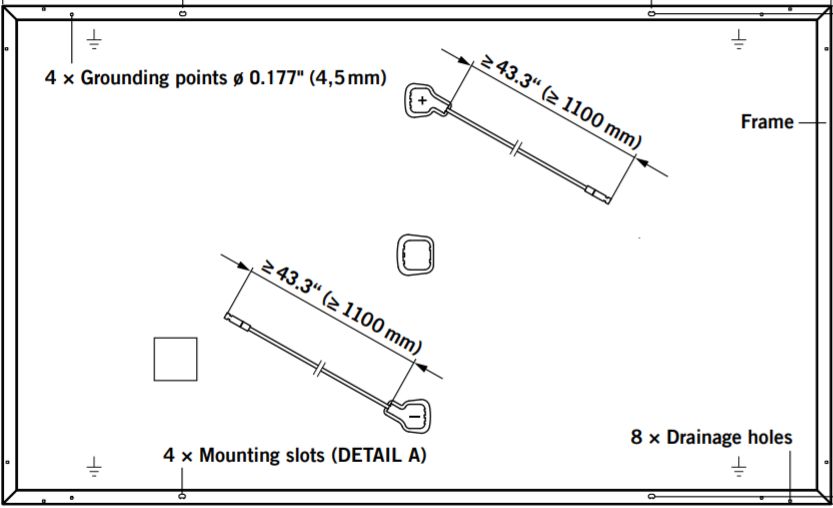
You can also read