WeatherSense Solar Powered Air Quality Sensor Assembly and Test Manual February 2021 Version 1.2 - Version 1.2 February 2021
←
→
Page content transcription
If your browser does not render page correctly, please read the page content below
WeatherSense
                     Solar Powered Air Quality Sensor
                        Assembly and Test Manual

                             February 2021
                              Version 1.2

Version 1.2 February 2021
Table of Contents
Cautions when building and using WeatherSense Sensors ............................................................................... 2
Errata ..................................................................................................................................................................... 2
What is The WeatherSense Solar Powered Air Quality Sensor? ..................................................................... 6
Before You Build Your WeatherSense AQ ........................................................................................................ 7
Step by Step Assembly and Parts List ................................................................................................................ 8
  What are we doing here? .................................................................................................................................. 8
  Parts List ............................................................................................................................................................ 8
  Parts you need to buy separately from the kit .............................................................................................. 11
  How to select a LiPo Battery .......................................................................................................................... 11
  Step by Step Assembly .................................................................................................................................... 12
Testing WeatherSense AQ ................................................................................................................................. 18
  What does the JSON from the WeatherSenseAQ Sensor mean? ............................................................... 20
Optional: Reducing the power needed for your WeatherSenseAQ ............................................................... 22
Disclaimer ............................................................................................................................................................ 24

Cautions when building and using WeatherSense Sensors
     1) Keep all water away from the electronics and power supply at all times!
     2) This is not a toy! Keep it out of reach of young children and pets.
     3) SwitchDoc Labs assumes no liabilities in the use of this kit, beyond the refund of the purchase price.

Errata

Version 1.2 February 2021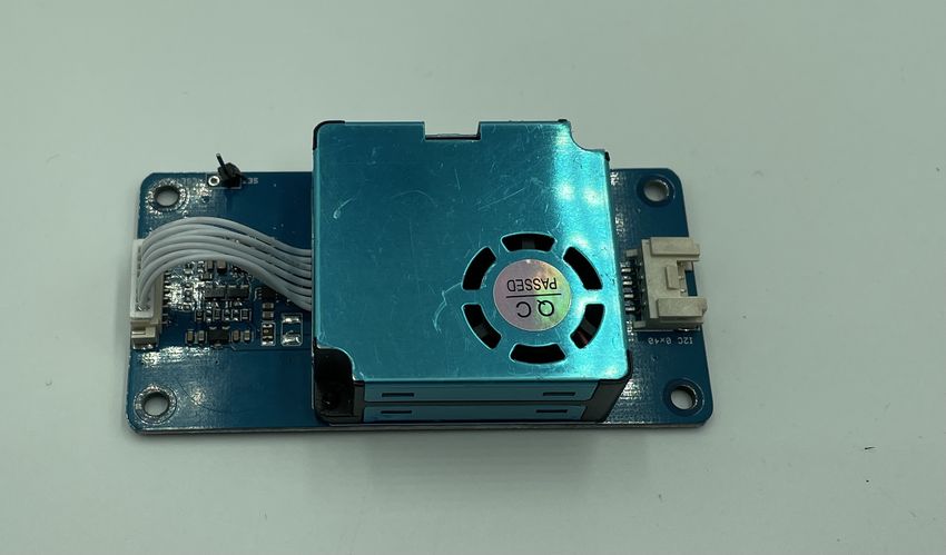
What is The WeatherSense Solar Powered Air Quality Sensor?

Easy to build. Easy to learn about the IOT (Internet Of Things) and the Raspberry Pi.

The heart of the new WeatherSense Sensors is the our new 433MHz MiniProPlus CPU board in working in
conjunction with the HM3301 Laser Air Quality Sensor.

The WeatherSense Air Quality kit is so simple that even middle school children can build it with just a little
adult help for configuration and installation.

6 Page
Version 1.2 February 2021
Full Open Source Arduino IDE compatible C Software that you can Modify and the open source Python3
software for the Raspberry Pi.

We provide the Python3 software (for the Raspberry Pi) and C for the WeatherSense AQ. All open source with
the kit. The Pure Python software can be modified to add new sensors, support new cloud software and connect
up to your own projects and software.

Before You Build Your WeatherSense AQ

You should build and test your WeatherSense AQ system as below BEFORE you put it in the option 3D Printed
case. Get it working first, then put it in the case. Believe us, it is always easier to debug the system before you
close it up in the case! The manual for the case and weatherproofing is called the “WeatherSense AQ
Weatherproofing, Assembly and Test Manual”. All manuals are available on the WeatherSense AQ Product
page on shop.switchdoc.com.

7 Page
Version 1.2 February 2021
Step by Step Assembly and Parts List
Cautions: Keep your static charge to a minimum during your assembly and operation. Touch metal before
handling parts. Avoid shuffling your feet. Before starting assembly, layout all the parts above and familiarize
yourself with the various parts.
What are we doing here?
We are assembling the WeatherSense AQ System.
In this manual, we are going to assemble the WeatherSense AQ system and test all the functions. If you plan to
put WeatherSense AQ outside, and after you complete this manual, proceed to the “WeatherSense AQ
Weatherproofing, Assembly and Test Manual” on the WeatherSense AQ Product Page.
Parts List
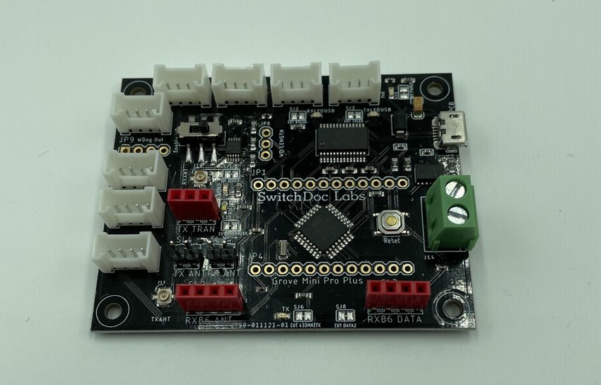
Part A Part B
SwitchDoc Labs Grove Mini Pro Plus Short USB A to Micro USB
8 Page
Version 1.2 February 2021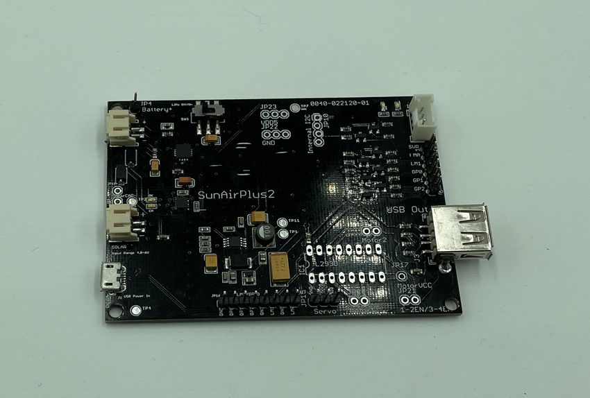
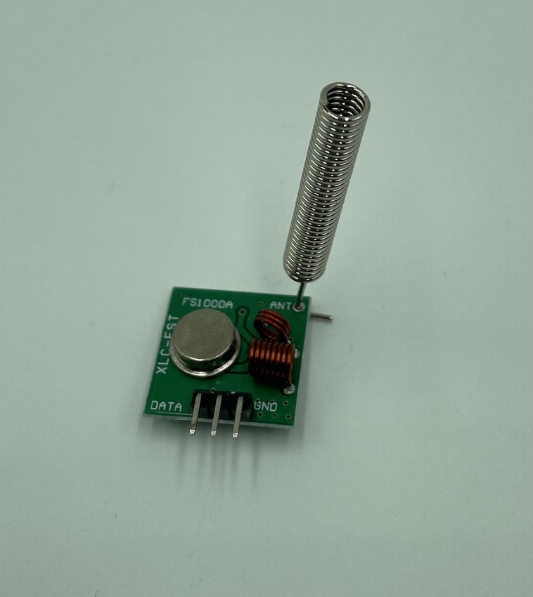
Part C                            Part D
     433MHz Transmitter with Antenna            HM3301 Laser Quality Sensor

9 Page
Version 1.2 February 2021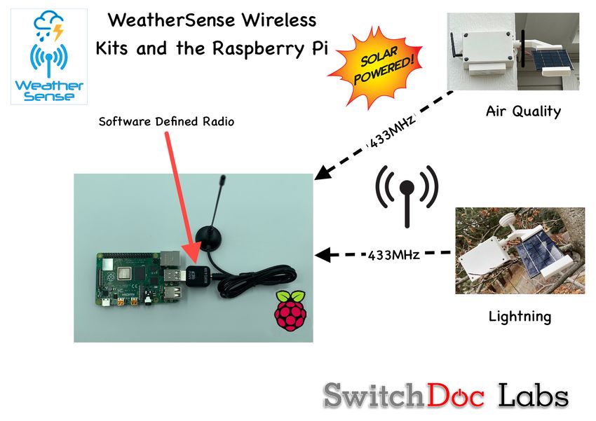
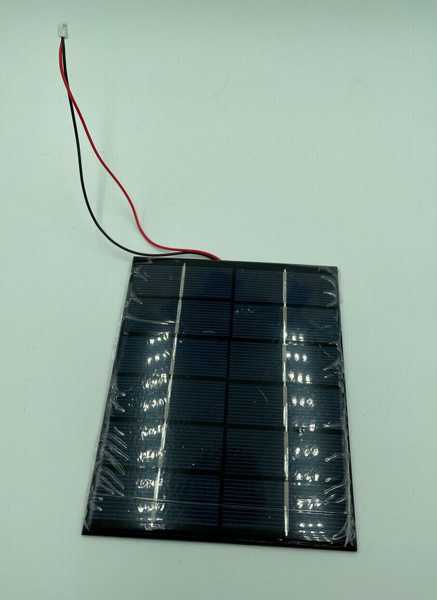
Part E                             Part F
     330mA 6V Solar Panel               SunAirPlus2 Solar Power Data Collector
                                        and Controller

     Part G                             Part H
     3.7V LiPo Battery (Not included)   Two (2) 20cm Grove Cables

10 Page
Version 1.2 February 2021
Parts you need to buy separately from the kit
• 3.7V LiPo Battery
• Raspberry Pi
• Compatible SDR Software Defined Radio (For example: https://hpjhlytllzrwf4qn-
24552113.shopifypreview.com/products/software-defined-radio-sdr-and-antenna )
• 16GB SD Card (unless you bought the SD Card from SwitchDoc Labs)
• Power Supply for the Raspberry Pi
How to select a LiPo Battery
The WeatherSense AQ requires 3.7V LiPo battery.
How large of a LiPo battery you need depends on how much sun you get and how often you have cloudy
weather. Generally, we would recommend a 6600mAh battery such as https://www.adafruit.com/product/353.
Adafruit has a great selection and you can find good ones on SparkFun.com too.
WARNING: if you get them off of Amazon, check the wiring. Most of them are wired backwards.
Here's a great website showing the problem and how to rewire the batteries if you wish:
https://docs.particle.io/tutorials/learn-more/batteries/
11 Page
Version 1.2 February 2021Step by Step Assembly Remember you are putting together the WeatherSense AQ to do testing and debugging. You will need to disassemble the unit and follow the assembly instructions in the WeatherSense AQ WeatherProofing and System Testing Manual. Step 1: Lay out all parts on a flat non-conductive (J) surface. Step 2: Plug in the 433MHz Transmitter (Part C) into the MiniProPlus (Part A) three pin female header market TX Tran. Make sure it is oriented as shown in the picture. Make sure the pins are slightly bent out as in the second picture. This makes sure that the pins are connected in the header. 12 Page Version 1.2 February 2021
Step 3: Take a grove cable (Part H) and plug it into the grove connection on the Mini Pro Plus (Part A) marked
J5-I2C and the other end into the grove connector on the Air Quality Sensor (Part D).

Step 4: Push the WatchDog Time Enable Switch to the Left (enable) on the Mini Pro Plus board (Part A).

13 Page
Version 1.2 February 2021
Step 5: Take the other grove cable (Part H) and plug it in into the Mini Pro Plus (Part A) grove connector
marked J7-I2C and the other end into the grove connector on the SunAirPlus2 board (Part F).

Step 6: take the USB micro to Type A cable (Part B) and plug it into the USB micro connector on the
MiniProPlus board (Part A) and the other end into the TypeA connector on the SunAirPlus2 Board (Part F).

14 Page
Version 1.2 February 2021
Step 7: Make sure the switch on the SunAirPlus2 board (Part F) is pushed toward the Battery Connector (away
from the Grove Connector). This turns off the power supply to the MiniProPlus (Part A)

15 Page
Version 1.2 February 2021
Step 8: Plug the Solar Panel (Part E) JST-2 connector into the SunAirPlus2 (Part F) board JST-2 plug marked
SOLAR (next to the USB Micro connector on SunAirPlus2 (Part F)). You can take the protective plastic off of
the solar panel (Part E) at this time.

16 Page
Version 1.2 February 2021
Step 9: Plug your LiPo Battery (Part G – not included) into the JST-2 connector marked Battery (near the
power switch) on the SunAirPlus2 board (Part F).

Step 10: Push the switch on the SunAirPlus2 (Part F) board away from the battery connector. You should see
LED lights come on on both boards.

Step 11: After 30 seconds (warm up time of the AQI sensor) you will see the LED market TX flash on the
MiniProPlus (Part A). A message has been sent and should have been received by your Raspberry Pi software.

Step 12: The AQI board will send a message every 18 minutes (thereabouts) giving the latest AQI readings and
all the solar power data. You can see the graphs on the dash_app once you have started the WeatherSense
Software (see below).

Step 13: Turn off the SunAirPlus2 (Part F) board by pushing the switch towards the battery connector

17 Page
Version 1.2 February 2021
You have now completed initial assembly. Now on to testing.

Testing WeatherSense AQ
If you have the SwitchDoc Labs SD Card, you can proceed to Step 4.

Step 1: Install the SDL modified version of rtl_433.

In a terminal window on your Pi at /home/pi type:

18 Page
Version 1.2 February 2021
git clone https://github.com/switchdoclabs/rtl_433.git

Then compile it on the Raspberry Pi:
cd rtl_433/
mkdir build
cd build
cmake ..
make
make install

Step 2: Install the WeatherSense AQ Software using these commands:

cd
git clone https://github.com/switchdoclabs/SDL_Pi_WeatherSense.git

Step 3: Add needed python modules to your system (a list will be provided on forum.switchdoc.com in the near
future). If you want to jump into it, run

sudo python3 WeatherSenseMonitor.py

And start adding in the missing libraries as they come up as missing imports, otherwise do at least the
following:

Installing mariadb:
https://pimylifeup.com/raspberry-pi-mysql/

sudo apt-get install python3-dev libmysqlclient-dev
sudo pip3 install mysqlclient

Next:

sudo -u root -p < WeatherSenseWireless.sql

Step 4: Note the IP Address of your Raspberry Pi. Type in the following commands to get your IP address:

hostname -I

You will get something like this:

pi@SwitchDocLabs:~/SDL_Pi_WeatherSense AQ $ hostname -I
192.168.1.44

Step 5: Update WeatherSense to the latest version. Type the following commands into a terminal window.

cd
cd SDL_Pi_WeatherSense
git pull

You will see something like this:

pi@SwitchDocLabs:~/SDL_Pi_WeatherSense$ git pull

19 Page
Version 1.2 February 2021
remote: Enumerating objects: 19, done.
remote: Counting objects: 100% (19/19), done.
remote: Compressing objects: 100% (2/2), done.
remote: Total 12 (delta 10), reused 12 (delta 10), pack-reused 0
Unpacking objects: 100% (12/12), done.
From https://github.com/switchdoclabs/SDL_Pi_WeatherSense AQ
   f2193a0..c98a45c master      -> origin/master
Updating f2193a0..c98a45c
Fast-forward
 README.md              | 2 ++
 SkyCamera.py           | 2 +-
 WeatherSense AQ.py         | 2 +-
 pclogging.py           | 12 +++++++-----
 state.py               | 3 +++
 testWirelessSensors.py | 18 ++++++++----------
 6 files changed, 22 insertions(+), 17 deletions(-)

Or, if your software is up to date:

pi@SwitchDocLabs:~/SDL_Pi_WeatherSense$ git pull
Already up to date.

Step 6: First we will test the reception of the wireless weather sensors. Test your SDR and WeatherSense
installation as follows. Note you must have completed the WeatherSenseAQ assembly.

cd /home/pi/SDL_Pi_WeatherSense

sudo python3 WeatherSenseMonitor.py

Turn on your WeatherSense AQ sensor by using the switch on the SunAirPlus2 board. You will then see
something similar to this on your terminal window:

pi@SwitchDocLabs:~/SDL_Pi_WeatherSense $ sudo python3 WeatherSenseMonitor.py
Pending jobs:
    readSensors (trigger: date[2021-02-27 12:13:55 PST], pending)
-----------------

Scheduled Jobs
######
-----------------
Read Wireless Sensors
######
Jobstore default:
    No scheduled jobs
-----------------
starting 433MHz scanning
######
processing AQI Data
This is the raw data: {"time" : "2021-02-27 12:49:58", "model" : "SwitchDoc Labs AQI", "len" : 46,
"messageid" : 0, "deviceid" : 1, "protocolversion" : 1, "softwareversion" : 1,
"weathersenseprotocol" : 15, "PM1.0S" : 3, "PM2.5S" : 4, "PM10S" : 4, "PM1.0A" : 3, "PM2.5A" : 4,
"PM10A" : 4, "AQI" : 16, "loadvoltage" : 4.960, "batteryvoltage" : 4.160, "batterycurrent" :
154.000, "loadcurrent" : 77.100, "solarpanelvoltage" : 3.032, "solarpanelcurrent" : -0.000, "auxa"
: 3, "mic" : "CRC"}

What does the JSON from the WeatherSenseAQ Sensor mean?

The WeatherSenseMonitor.py python3 program reads in the 433MHz signals into the Raspberry Pi, decodes
them and formats the results as a JSON packet that will be provided to the WeatherSenseMonitoring software

20 Page
Version 1.2 February 2021
for processing and storage in the database. More about the SDL_Pi_WeatherSense software in the
WeatherSense Software Manual.
If you have other WeatherSense Sensors (such as SkyWeather2, WeatherRack2, F016TH Indoor sensors, etc),
you will see them show up in the list too.
processing AQI Data
This is the raw data: {"time" : "2021-02-27 12:49:58", "model" : "SwitchDoc Labs AQI", "len" : 46,
"messageid" : 0, "deviceid" : 1, "protocolversion" : 1, "softwareversion" : 1,
"weathersenseprotocol" : 15, "PM1.0S" : 3, "PM2.5S" : 4, "PM10S" : 4, "PM1.0A" : 3, "PM2.5A" : 4,
"PM10A" : 4, "AQI" : 16, "loadvoltage" : 4.960, "batteryvoltage" : 4.160, "batterycurrent" :
154.000, "loadcurrent" : 77.100, "solarpanelvoltage" : 3.032, "solarpanelcurrent" : -0.000, "auxa"
: 3, "mic" : "CRC"}
The values and units of the are:
• timestamp: When the packet has been received
• model: SwitchDoc Labs AQI
• len: Number of bytes in the packet
• messageid: Reset to 0 on bootup
• deviceid: 1 – If you have more than one AQ sensor, you can change this ID by recompiling the software
• protocolversion: Current protocol of the AQ sensor
• softwareversion: This shows the current version of the software on the Mini Pro Plus
• weathersenseprotocol: 15 for WeatherSenseAQ
• PM1.0S – concentration of 1.0 micron particles ug/m***3 (Standard)
• PM2.5S– concentration of 2.5 micron particles ug/m***3 (Standard)
• PM1.0S – concentration of 10 micron particles ug/m***3 (Standard)
• PM1.0A – concentration of 1.0 micron particles ug/m***3 (Atmospheric)
• PM2.5A– concentration of 2.5 micron particles ug/m***3 (Atmospheric)
• PM1.0S – concentration of 10 micron particles ug/m***3 (Atmospheric)
• AQI – The Air Quality Index of the above data – EPA calculation
The solar data collected by the device is:
• loadvoltage: Voltage supplied to the computer (V)
• batteryvoltage: Voltage of the LiPo Battery (V)
• batterycurrent: Current being supplied by the battery (mA)
• loadcurrent: Current being supplied to the computer (mA)
• solarpanelvoltage: Voltage of the Solar Panel (V)
• solarpanelcurrent: Current being supplied by the Solar Pane (mA)
The AuxA variable contains state information about what sensors the WeatherSenseAQ has connected to and if
the sensor is in low voltage mode.
Each bit of the lower four bits of the AuxA variable (0CAB) are coded as:
C = 1, Voltage below 2.9, HM3301 not turned on, 0 means normal operation
A = 1, SunAirPlus2 (Solar) Present, 0 not present
B = 1, HM3301 Present, 0 not present
21 Page
Version 1.2 February 2021You now have completed testing of your WeatherSenseAQ sensor. If you would like to further reduce the power needed by the Laser Air Quality Sensor, you may do the following optional assembly. This does require soldering! Otherwise, print your 3D Prints and move on over to the WeatherSenseAQ Weatherproofing manual. Then take a look at the WeatherSense software manual for the Raspberry Pi. Optional: Reducing the power needed for your WeatherSenseAQ The Laser Air Quality sensor takes about 80mA of current when it is running. By doing the following, this allows the WeatherSenseAQ to turn off the Laser Air Quality sensor when it is not being used which saves a substantial amount of power. By doing this, the Laser Air Quality sensor will only be on for about 30 seconds out of each 18 minute cycle. Much less power! Step 1: Turn off your WeatherSense AQ and remove the Laser Air Quality Sensor (Part D). Step 2: Solder a single Pin Header in the hole market “SET” on the Laser Air Quality Sensor. 22 Page Version 1.2 February 2021
Step 3: Take a Grove to Pin Header Adaptor Cable ( https://shop.switchdoc.com/products/grove-4-pin-female-
jumper-to-grove-4-pin-conversion-cable-5-pcs-per-pack ) and cut off the black, red and white wires, making
sure they do not short together (stagger them or cover them with electrical tape). If you choose to make your
own jumper make sure you use the left most pin in the Grove connector.

23 Page
Version 1.2 February 2021
Step 4: Plug your modified Grove to Pin Header Adaptor cable into the Grove Connector marked J6-D2/D3 on
the Mini Pro Plus Board (Part A). Plug the yellow wire onto the SET pin you soldered on the Laser Air Quality
Sensor (Part D) in Step 2.

Step 5: Replace the Grove cable (Part H) going from the Laser Air Quality Sensor (Part D) to the Grove
connector marked J5-I2C.

This completes the low power modification.

Disclaimer
SwitchDoc Labs, LLC takes no responsibility for any physical injuries and possession loss caused by those
reasons which are not related to product quality, such as operating without following the operating manual and
cautions, natural disasters or force majeure.
SwitchDoc Labs, LLC has compiled and published this manual which covers the latest product description and
specification. The contents of this manual are subject to change without notice.

24 Page
Version 1.2 February 2021
You can also read