UG65 GATEWAY QUICK START GUIDE - MILESIGHT IOT
←
→
Page content transcription
If your browser does not render page correctly, please read the page content below
UG65 Gateway
Quick Start Guide

                    Milesight IoT
Safety Precautions
Milesight will not shoulder responsibility for any loss or damage resulting from not following the
instructions of this operating guide.
The device must not be modeled in any way.
Do not place the device close to objects with naked flames.
Do not place the device where the temperature is below/above the operating range.
Do not power on the device or connect it to other electrical device when installing.
Check lightning and water protection when used outdoors.
Do not connect or power the equipment using cables that have been damaged.
Related Documents
This Quick Start Guide only explains the installation of Milesight UG65 LoRaWAN® Gateway. For more
functionality and advanced settings, please refer to the relevant documents as below.
Document Description
UG65 Datasheet Datasheet for UG65 LoRaWAN® Gateway.
Users can refer to the guide for instruction on how to log in the web GUI, and
UG65 User Guide
how to configure all the settings.
The related documents are available on Milesight website: https://www.milesight-iot.com
Declaration of Conformity
UG65 is in conformity with the essential requirements and other relevant provisions of the CE, FCC, and
RoHS.
For assistance, please contact
Milesight technical support:
Email: iot.support@milesight.com
Tel: 86-592-5085280
Fax: 86-592-5023065
Revision History
Date Doc Version Description
Aug. 31, 2020 V1.0 Initial version
Nov. 24, 2020 V2.0 Layout replace
May 6, 2021 V2.1 Layout replace
2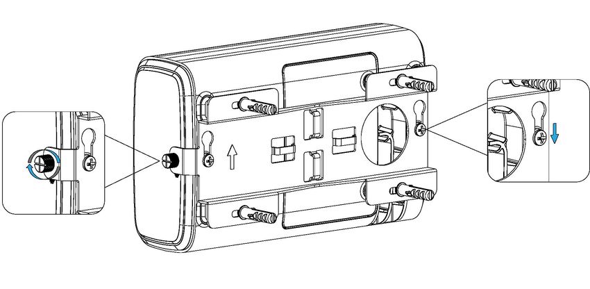
Contents

1. Packing List....................................................................................................................................................4
2. Hardware Introduction................................................................................................................................. 5
     2.1 Overview...............................................................................................................................................5
     2.2 Dimensions (mm)............................................................................................................................... 5
     2.3 LED Indicators..................................................................................................................................... 6
     2.4 Reset Button........................................................................................................................................ 6
3. Hardware Installation................................................................................................................................... 7
     3.1 SIM Card Installation.......................................................................................................................... 7
     3.2 Ethernet Cable & Power Cable Installation..................................................................................... 7
     3.3 Antenna Installation........................................................................................................................... 7
     3.4 Gateway Installation...........................................................................................................................8
          3.4.1 Wall Mounting.......................................................................................................................... 8
          3.4.2 Pole Mounting.......................................................................................................................... 9
4. Login the Web GUI...................................................................................................................................... 10
     4.1 Wireless Access................................................................................................................................10
     4.2 Wired Access.....................................................................................................................................11
5. Network Connection................................................................................................................................... 13
     5.1 Configure the Ethernet Connection................................................................................................13
     5.2 Configure the Wi-Fi Connection...................................................................................................... 13
     5.3 Configure the Cellular Connection................................................................................................. 14
6. Packet Forwarder Configuration...............................................................................................................16
7. Network Server Configuration...................................................................................................................18
     7.1 Connect UG65 to Milesight IoT Cloud........................................................................................... 18
     7.2 Connect UG65 to MQTT/HTTP Server...........................................................................................20

                                                                                                                                               3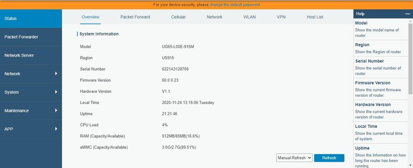
1. Packing List
Before you begin to install the UG65 LoRaWAN® Gateway, please check the package contents to verify
that you have received the items below.

       1 × UG65            1 × Ethernet Cable    1 × DC Jack Power Adapter     1 × Mounting Bracket

 Bracket Fixing Screws      Wall Mounting Kits         1 × Warranty Card        1 × Quick Start Guide

   1 × LoRa Antenna

   (External antenna

   version included)

    If any of the above items is missing or damaged, please contact your sales representative.

                                                                                     4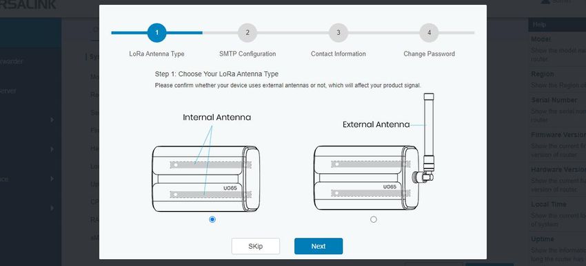
2. Hardware Introduction

2.1 Overview
A. Front Panel

                           1   LED Area
                           POWER: Power Indicator
                           STATUS: System Indicator
                           LoRa: LoRa Indicator
                           Wi-Fi: Wi-Fi Indicator
                           LTE: Cellular Indicator
                           ETH: Ethernet Port Indicator
                           2    LoRa Antenna Connector
                           (only for external antenna version)
B. Rear Panel

                           3    Bracket Mounting Screws
                           4    SIM Slot
                           5    Type-C Port
                           6    Ethernet Port (PoE)
                           7    Power Connector
                           8    Reset Button
                           9    Waterproof Silicone
                           10   Cable Groove

2.2 Dimensions (mm)

                                                                 5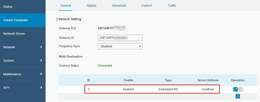
2.3 LED Indicators
    LED       Indication          Status         Description
                                  Off            The power is switched off
    POWER     Power Status
                                  On             The power is switched on
                                  Blue Light     Static: the system is running properly
    STATUS    System Status
                                  Red Light      The system goes wrong
                                  Off            Packet Forwarder mode is running off
    LoRa      LoRa Status
                                  Blue Light     Packet Forwarder mode is running well
                                  Off            Wi-Fi is disabled
    Wi-Fi     Wi-Fi Status
                                  Blue Light     Wi-Fi is enabled
                                                 SIM card is registering or fails to register
                                  Off
                                                 (or there are no SIM cards inserted)
                                                 Blinking slowly: SIM card has been registered
                                                 and is ready for dial-up
    LTE       Cellular Status
                                                 Blinking rapidly: SIM card has been registered
                                  Blue Light
                                                 and is dialing up now
                                                 Static: SIM card has been registered and dialed
                                                 up successfully
              Ethernet            Off            Disconnected
    ETH
              Port Status         Blue Light     Static: Connected

2.4 Reset Button
              Description
   Function
              STATUS LED                Action
              Static Blue               Press and hold the reset button for more than 5 seconds.
              Static Blue →
   Reset                                Release the button and wait.
              Rapidly Blinking
              Off → Static Blue         The gateway resets to factory default.

                                                                                                6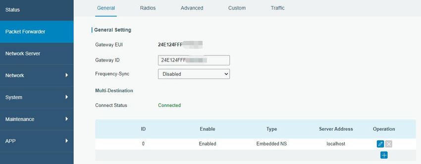
3. Hardware Installation
3.1 SIM Card Installation
A. Use screwdriver to open the protective cover on the back panel of UG65.
B. Insert the SIM card into the device according to the direction icon on the device.
Note:
If you need to take out the SIM card, press into the SIM card and it will pop up automatically.
UG65 does not support hot plugging (also called hot swapping). please turn off the power before
you insert or take off cards.
3.2 Ethernet Cable & Power Cable Installation
A. Connect the Ethernet cable and power cable to corresponding interfaces.
B. Pass two cables through the waterproof silicone and slid into the grooves.
C. Screw the protective cover back to the device.
UG6x can also be powered by 802.3af standard PoE injector or other PoE devices. If both connected, DC
power is preferred.
Note: When connecting, Ethernet cable of UG65 device side should be installed first, otherwise, PoE
devices or gateway may be damaged.
3.3 Antenna Installation
For external antenna version, rotate the antenna into the antenna connector accordingly.
The external antenna should be installed vertically always on a site with a good signal.
7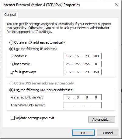
Note: Please do not let the front panel of products faces to walls if using embedded LoRa antennas.

3.4 Gateway Installation
UG65 can be mounted to a wall or a pole. Before you start, make sure that your SIM card has been
inserted, your antennas have been attached and all cables have been installed.

3.4.1 Wall Mounting
Preparation: mounting bracket, bracket fixing screws, wall plugs, wall mounting screws and other
required tools.
1. Align the mounting bracket horizontally to the desired position on the wall, use a marker pen to mark
four mounting holes on the wall, and then remove the mounting bracket from the wall.
Note: The connecting lines of adjacent points are at right angles.
2. Drill four holes with a depth of 32 mm by using your drill with a 6 mm drill bit on the positions you
marked previously on the wall.
3. Insert four wall plugs into the holes respectively.
4. Mount the mounting bracket horizontally to the wall by fixing the wall mounting screws into the wall
plugs.

5. Screw the bracket fixing screws to the back panel of device, then hang the device to the mounting
bracket on the wall.

                                                                                            8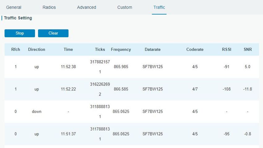
3.4.2 Pole Mounting
Preparation: mounting bracket, bracket fixing screws, hose clamp and other required tools.
1. Loosen the hose clamp by turning the locking mechanism counter-clockwise.
2. Straighten out the hose clamp and slide it through the rectangular rings in the mounting bracket,
wrap the hose clamp around the pole.
3. Use a screwdriver to tighten the locking mechanism by turning it clockwise.

4. Screw the bracket fixing screws to the back panel of device, then hang the device to the mounting
bracket on the pole.

                                                                                           9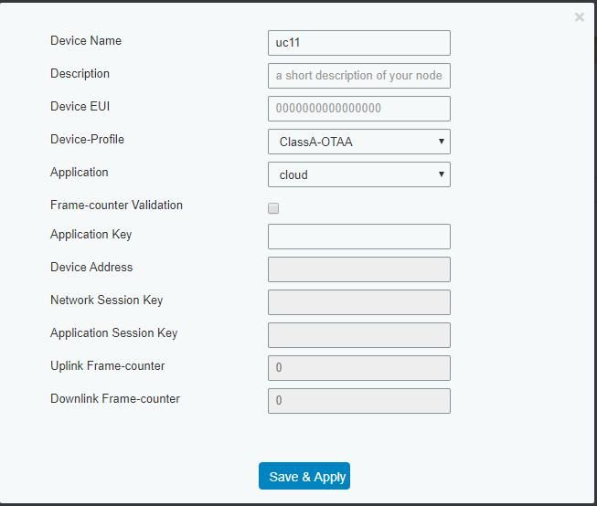
4. Login the Web GUI
UG65 provides web-based configuration interface for management. If this is the first time you configure
the gateway, please use the default settings below:
ETH IP Address: 192.168.23.150
Wi-Fi IP Address: 192.168.1.1
Wi-Fi SSID: Gateway_******
Username: admin
Password: password
4.1 Wireless Access
A. Enable Wireless Network Connection on your computer and search for access point “Gateway_******”
to connect it.
B. Open a Web browser on your PC (Chrome is recommended) and type in the IP address 192.168.1.1 to
access the web GUI.
C. Enter the username and password, click “Login”.
If you enter the username or password incorrectly more than 5 times, the login page will be
locked for 10 minutes.
D. After logging the web GUI, follow the guide to complete the basic configurations. You can also skip
the instructions. It’s suggested that you change the password for the sake of security.
E. You can view system information and perform configuration of the gateway.
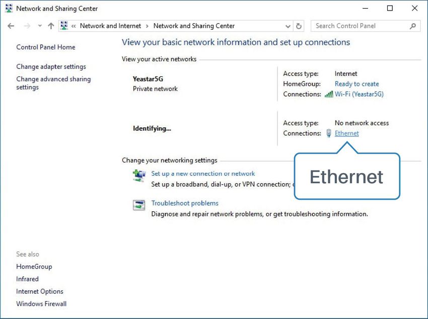
104.2 Wired Access
Connect PC to UG65 ETH port through PoE injector. The following steps are based on Windows 10
operating system for your reference.
A. Go to “Control Panel” → “Network and Internet” → “Network and Sharing Center”, then click
“Ethernet” (May have different names).
B. Go to “Properties” → “Internet Protocol Version 4(TCP/IPv4) ”and select “Use the following IP
address”, then assign a static IP manually within the same subnet of the gateway.
C. Open a Web browser on your PC (Chrome is recommended) and type in the IP address 192.168.23.1
50 to access the web GUI.
11D. Enter the username and password, click “Login”.
If you enter the username or password incorrectly more than 5 times, the login page will be
locked for 10 minutes.
E. After logging the web GUI, follow the guide to complete the basic configurations. You can also skip
the instructions. It’s suggested that you change the password for the sake of security.
F. After guide complete, you can view system information and perform configuration of the gateway.
125. Network Connection
This section explains how to connect the gateway to network via WAN connection, Wi-Fi or cellular.
5.1 Configure the Ethernet Connection
A. Go to “Network”→ “Interface” → “Port” page to select the connection type and configure Ethernet
port information.
B. Click “Save & Apply” for changes to take effect.
C. Connect Ethernet port of gateway to devices like router or modem.
D. Log in the web GUI via the newly assigned IP address and go to “Status”→ “Network” to check
Ethernet port status.
5.2 Configure the Wi-Fi Connection
A. Go to “Network” → “Interface” → “WLAN” and select “Client” mode.
B. Click “Scan” to search for Wi-Fi access point. Select the available one and click “Join Network”.
13C. Type the key of Wi-Fi.
D. Go to “Status”→”WLAN” to check Wi-Fi status. If it shows “Connected”, it means gateway connects to
Wi-Fi successfully.
5.3 Configure the Cellular Connection
A. Go to “Network” → “Interface” → “Cellular” → “Cellular Setting” page to enable cellular settings.
14B. Choose relevant network type and fill in SIM card information like APN or PIN code.
C. Click “Save” and “Apply” for changes to take effect.
D. Go to “Status” → “Cellular” page to view the status of the cellular connection. If it shows “Connected”,
it means the SIM has dialed up successfully. On the other hand, you can check the status of LTE
indicator. If it keeps on light statically, it means SIM has dialed up successfully.
156. Packet Forwarder Configuration
UG65 has installed multiple packet forwarders including Semtech, Chirpstack-Generic MQTT broker, etc.
This section explains how to connect the gateway to network servers.
Make sure the gateway connects to the network as shown in Section 5.
A. Go to “Packet Forwarder” → “General” page and click to add a network server.
B. Fill in the server information and enable this server.
C. Go to “Packet Forwarder” → “Radio” page to configure antenna type, center frequency and channels.
The channels of the gateway and network server need to be the same.
16D. Add the gateway on network server page. For more details about the network server connection
please refer to Milesight IoT Support portal.
E. Go to “Traffic” page to view the data communication of UG65.
177. Network Server Configuration
UG65 can work as network server and transmit data to Milesight IoT Cloud or other platform via
MQTT/HTTP/HTTPS.
Make sure the gateway connects to the network as shown in Section 5.
7.1 Connect UG65 to Milesight IoT Cloud
A. Go to “Packet Forwarder” → “General” page to enable the embedded network server.
B. Go to “Packet Forwarder” → “Radio” page to select the antenna type, center frequency and channels.
The channels of the gateway and nodes need to be the same.
C. Go to “Network Server” → “General” page to enable the network server and “Milesight IoT Cloud”
mode.
18D. Log in the Milesight IoT Cloud. Then go to “My Devices” page and click “+New Devices” to add
gateway to Milesight IoT Cloud via SN. Gateway will be added under “Gateways” menu.
E. The gateway is online on Milesight IoT Cloud.
197.2 Connect UG65 to MQTT/HTTP Server
A. Go to “Packet Forwarder” → “General” page to enable the embedded network server.
B. Go to “Packet Forwarder” → “Radio” page to select the antenna type, center frequency and channels.
The channels of the gateway and nodes need to be the same.
C. Go to “Network Server” → “General” page to enable the network server mode.
20D. Go to “Network Server”→”Application” to add a new application.
After saving the application, you can select HTTP, HTTPS or MQTT protocol and fill in correspond server
information to send data to another server.
E. Go to “Profiles” page to add a new profile for the device.
21F. Go to “Device” page and click “Add” to add LoRaWAN® node devices.
You can also click “Bulk Import” if you want to add many nodes all at once.
Click “Template Download” to download template file and add device information to this file. Application
22and device profile should be the same as you created on web page.
Import this file to add bulks of devices.
F. Go to “Packets” page to check the packets from LoRaWAN® node devices. The type starts from “Up”
means uplinks and “Dn” means downlinks.
Click “Details” to check the properties and payload contents of packets.
[END]
23You can also read