NZ interface converter - TECHNICAL GUIDE (PCB board modification: NZ-4)
←
→
Page content transcription
If your browser does not render page correctly, please read the page content below
NZ interface converter
2-wire voltage driver circuit interface converter
(RS-485/RS-232 to 2-wire voltage driven circuit and backwards)

                   TECHNICAL GUIDE
                   (PCB board modification: NZ-4)

                   Review date: 21 March, 2020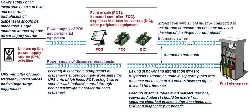
NZ INTERFACE CONVERTER TECHNICAL GUIDE
Revision number: 1.03                                                                                                           Review date: 21 March, 2020

                                                                      CONTENT
REVISION HISTORY ................................................................................................................................................ 3
PURPOSE OF THE DOCUMENT .............................................................................................................................. 4
APPOINTMENT ...................................................................................................................................................... 5
TECHNICAL SPECIFICATIONS ................................................................................................................................. 6
COMPLETE SET ...................................................................................................................................................... 7
PCB BOARD CONNECTORS OVERVIEW ................................................................................................................. 8
CONNECTION SCHEME TO PTS CONTROLLER ....................................................................................................... 9
CONNECTION SCHEME TO PC COM-PORT (DATA COMMUNICATION)...............................................................11
FIRMWARE UPDATE ............................................................................................................................................12
INSTALLATION REQUIREMENTS FOR PETROL STATION ......................................................................................14
EXAMPLES OF FUEL DISPENSERS CONNECTION SCHEMES .................................................................................16
    Gallagher (PEC) fuel dispenser connection ................................................................................................ 16
    Compac dispenser connection ................................................................................................................... 17
ORDER INFORMATION ........................................................................................................................................18

 www.technotrade.ua                                                                                                                              page 2 from 18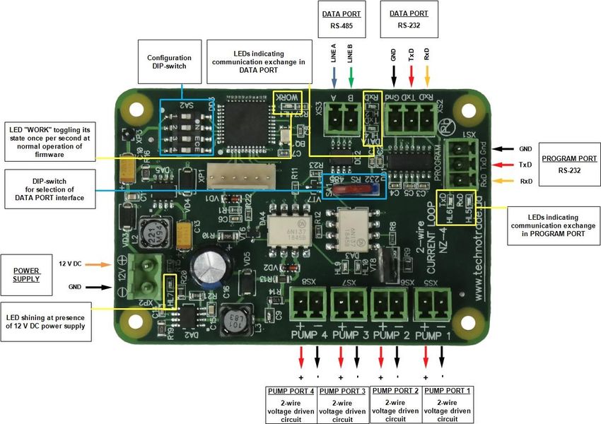
NZ INTERFACE CONVERTER TECHNICAL GUIDE
Revision number: 1.03                                                                   Review date: 21 March, 2020

 REVISION HISTORY

  REV        DATE         BY                     SECTION                             DESCRIPTION
  1.03     2020.03.21   Evgeniy    All                               Regular document review
                        Vasyliev

  1.02     2017.01.20   Evgeniy    Firmware update procedure         Firmware update procedure using 4th DIP-switch
                        Vasyliev                                     SA2

  1.01     2014.12.02   Evgeniy    All                               First release
                        Vasyliev

 www.technotrade.ua                                                                                  page 3 from 18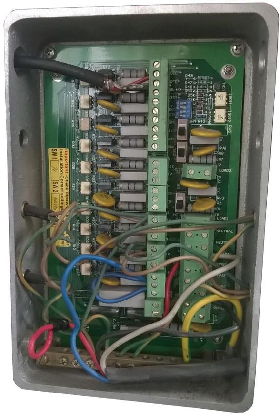
NZ INTERFACE CONVERTER TECHNICAL GUIDE
Revision number: 1.03                                                                Review date: 21 March, 2020

 PURPOSE OF THE DOCUMENT

 This Technical Guide is intended for studying of NZ interface converter for fuel dispensers for petrol
 stations. It contains basic information regarding its
     − technical characteristics
     − board interfaces and connectors
     − configuration
     − schemes of connection to fuel dispensers
     − cabling
 Information regarding connection to specific fuel dispensers and correspondent configuration of NZ
 interface converter can be received upon request to Technotrade LLC company.
 During the system development process given Technical Guide is also expanded and updated and new
 chapters are added. Latest version of this Technical Guide can be downloaded from the NZ interface
 converter web-page: http://www.technotrade.ua/compac-interface-converter.html.

 Technotrade LLC hereby permits reproduction of this document as may be required by any of the
 customers or OEMs wishing to use it.
 This document has been carefully prepared and is believed to be accurate. However, Technotrade LLC, its
 employees and its agents do not assume responsibility for its use either directly or indirectly. Technotrade
 LLC shall not be liable for technical or editorial errors or omissions which may appear in this document.
 Technotrade LLC reserves a right to make changes to this document at any time without notice. Prospective
 users of this document should contact Technotrade LLC at the time they wish to use NZ interface converter
 together with their products to become aware of any updates that may apply.
 In case if you find any mistakes, omissions in this document or have any suggestions on improvements to
 this document, please feel free to e-mail them to our support mailbox: support_1a@technotrade.ua. We
 will be grateful to you for this valuable information.
 All technical questions regarding the NZ interface converter are welcome to be asked on support mailbox:
 support_1a@technotrade.ua. Our support team will be glad to help you.

 Also, you can call to us or visit us on:

 Technotrade LLC
 Ukraine, 04114 Kiev, Priorska str. 10, office 1
 Tel: +38-044-502-46-55, +38-044-502-46-77
 Web: www.technotrade.ua
 Mail: mail@technotrade.ua

 www.technotrade.ua                                                                              page 4 from 18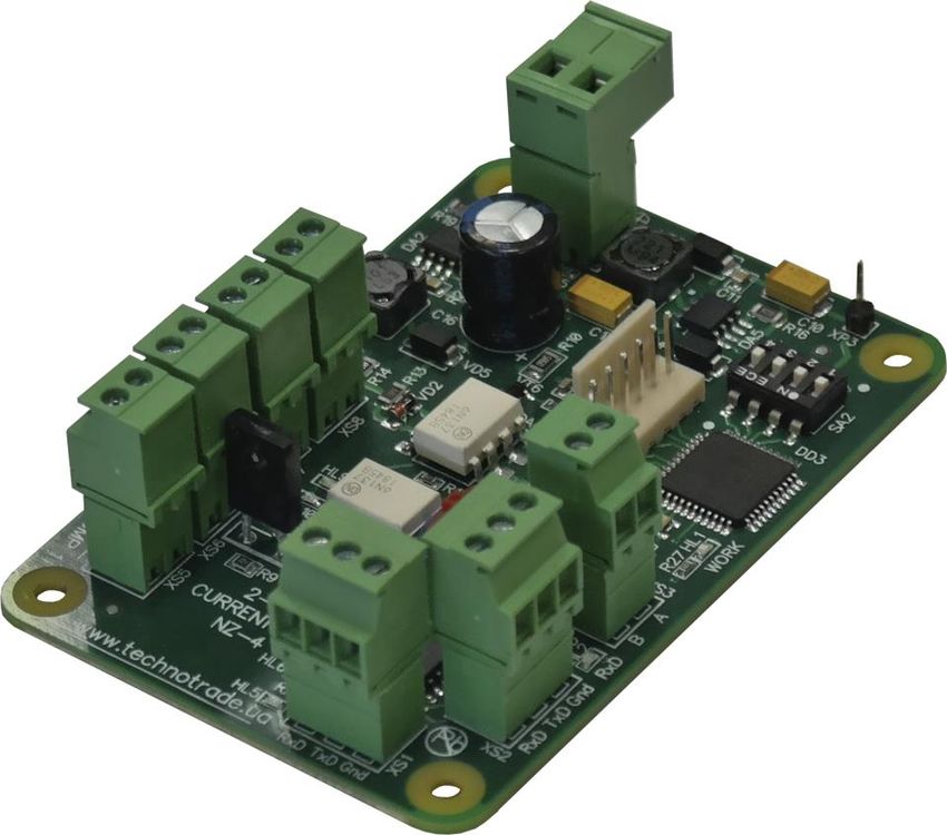
NZ INTERFACE CONVERTER TECHNICAL GUIDE
Revision number: 1.03                                                              Review date: 21 March, 2020

 APPOINTMENT

 NZ interface converter (RS-485/RS-232 to 2-wire voltage driven circuit and backwards) are intended for
 communication with fuel dispensers, which use 2-wire voltage driven circuit interface, through interfaces:
   - RS-232
   - RS-485 (2-wire)

 NZ interface converters can be applied for communication with following brands of fuel dispensers, which
 use 2-wire voltage driven circuit for communication with control systems:
   - Actronic
   - Agira
   - Batchen
   - Compac
   - Fuelquip
   - Intermech
   - PEC (Gallagher Fuel Systems)
   - Rix
   - Transponder
   - others

 www.technotrade.ua                                                                            page 5 from 18
NZ INTERFACE CONVERTER TECHNICAL GUIDE
Revision number: 1.03                                                              Review date: 21 March, 2020

 TECHNICAL SPECIFICATIONS

 Specification
           PARAMETER                                                VALUE
 Power supply voltage                                              12 V DC
 Current consumption                                             300 mA max
 Temperature range                                           From -40°C to +80°C
 Weight                                                              45 g
 Dimensions                                                    85 x 58 x 25 mm

 Communication ports
             PORT NAME               INTERFACE                               PURPOSE
                              RS-232
             RS-232                                       Communication with a control system (POS
                              (3 wires: TxD, RxD, Gnd)
   PORTS
   DATA

                                                          terminal, cash register, OPT). Selection of
                              RS-485
             RS-485                                       interface is made using DIP-switch SA2
                              (2-wires: line A, line B)
                              Optically isolated          Connection with fuel dispensers using 2 wires.
   PORTS
   PUMP

             Pump ports 1…4   voltage driven circuit      One dispenser is to be connected to each of the
                              (lines “+” and “-”)         pump ports.
   PROGRAM
     PORT

                              RS-232
             RS-232                                       Update of the interface converter firmware
                              (3 wires: TxD, RxD, Gnd)

 www.technotrade.ua                                                                            page 6 from 18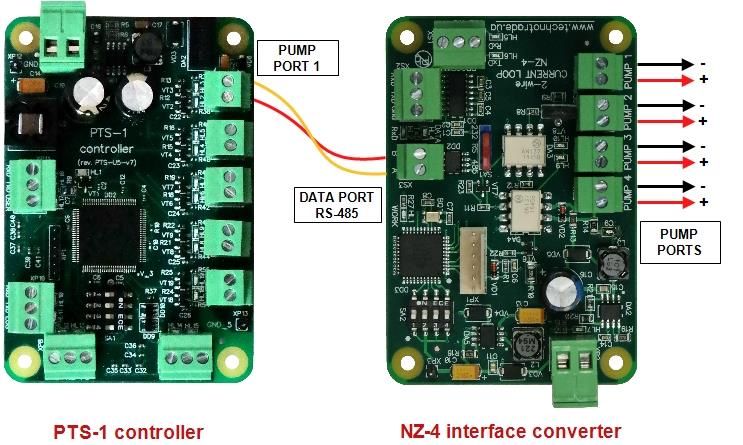
NZ INTERFACE CONVERTER TECHNICAL GUIDE
Revision number: 1.03 Review date: 21 March, 2020
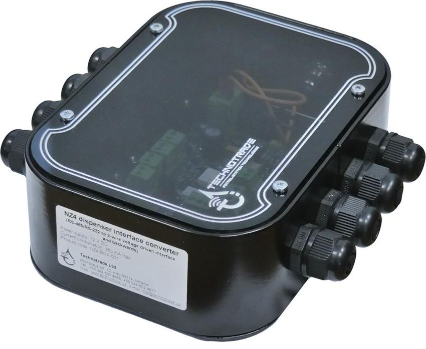
COMPLETE SET
Depending on the order code (see section “Order information”) NZ interface can be supplied either in a
view of electrical board (variant of converter supply NZ4-PCB-z), or installed in a mounting box with cables
inputs and a power switching button (variant of converter supply NZ4-BOX-z).
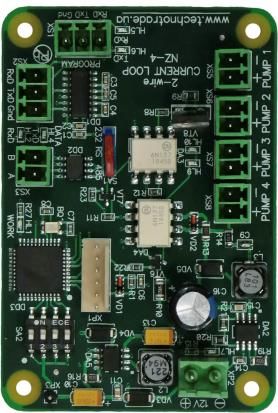
Variant of NZ-4 interface converter supply in a view of electrical board (NZ4-PCB-z)
Variant of NZ-4 interface converter supply installed in a plastic box with cables inputs and
power switching button (NZ4-BOX-z)
www.technotrade.ua page 7 from 18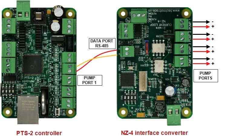
NZ INTERFACE CONVERTER TECHNICAL GUIDE
Revision number: 1.03                                                         Review date: 21 March, 2020

 PCB BOARD CONNECTORS OVERVIEW

 NOTE!

 DIP-switch SA1 serves for selection of interface:
  - RS-232
  - RS-485 (2-wire)

 DIP-switch SA2 serves for selection of interface converter operation mode:
  - switch 1 should be set in position “OFF”
  - switch 2 should be set in position “OFF”
  - switch 3 should be set in position “OFF”
  - switch 4 should be set in position “OFF”

 www.technotrade.ua                                                                       page 8 from 18
NZ INTERFACE CONVERTER TECHNICAL GUIDE
Revision number: 1.03                                                         Review date: 21 March, 2020

 CONNECTION SCHEME TO PTS CONTROLLER

 Connection scheme to PTS-1 controller (information about PTS controller over fuel dispensers and ATG
 systems can be found on PTS-1 controller web-page: http://www.technotrade.ua/fuel-pump-
 controller.html):

 Connection scheme to PTS-2 controller (information about PTS controller over fuel dispensers and ATG
 systems can be found on PTS-2 controller web-page: http://www.technotrade.ua/pts2-forecourt-
 controller.html):

 www.technotrade.ua                                                                       page 9 from 18
NZ INTERFACE CONVERTER TECHNICAL GUIDE
Revision number: 1.03                                                               Review date: 21 March, 2020

 At connection using RS-485 interface please check the following:

  ✓ DIP-switch SA1 should be in position “RS-485”
  ✓ DIP-switch SA2:
        - switch 1 should be set to position “OFF”
        - switch 2 should be set to position “OFF”
        - switch 3 should be set in position “OFF”
        - switch 4 should be set to position “OFF”
  ✓ LED HL1 “WORK” indicates normal operation of firmware, toggling its state once per second
  ✓ LED HL7 indicates presence of 12 V DC on the board, should be constantly shining
  ✓ Green and red LEDs “Tx” and “Rx”, which indicate communication exchange in DATA PORT, should be
    blinking, which indicates communication with the PTS controller over RS-485 interface:
        - in case if both LEDs “Rx” and “Tx” are not blinking – there are no requests from the control
            system and no responses from the dispenser.
        - in case if LED “Rx” is blinking and LED “Tx” is not blinking – there are requests from the control
            system (LED “Rx” is blinking), but there are no responses from the dispenser.
        - in case if LED “Rx” is blinking and LED “Tx” is blinking – there are requests from the control
            system (LED “Rx” is blinking) and there are responses from the dispenser (LED “Tx” is blinking).
  ✓ Green and red LEDs on pump ports, where the dispenser is connected, should be blinking, which
    indicates communication with the dispenser.

 www.technotrade.ua                                                                            page 10 from 18
NZ INTERFACE CONVERTER TECHNICAL GUIDE
Revision number: 1.03 Review date: 21 March, 2020
CONNECTION SCHEME TO PC COM-PORT (DATA COMMUNICATION)
Control over dispensers through the interface converter from a personal computer:
COM-port
Line “-”
TxD
Line “+”
Ports for connection
RxD
GND Line “-”
to dispensers
Line “+”
Line “-”
Line “+”
Personal computer Line “-”
Line “+”
NZ interface converter
At connection using RS-232 interface please check the following:
✓ DIP-switch SA1 should be in position “RS-232”
✓ DIP-switch SA2:
- switch 1 should be set to position “OFF”
- switch 2 should be set to position “OFF”
- switch 3 should be set in position “OFF”
- switch 4 should be set to position “OFF”
✓ LED HL1 “WORK” indicates normal operation of firmware, toggling its state once per second
✓ LED HL7 indicates presence of 12 V DC on the board, should be constantly shining
✓ Green and red LEDs “Tx” and “Rx”, which indicate communication exchange in DATA PORT, should be
blinking, which indicates communication with the PTS controller over RS-485 interface:
- in case if both LEDs “Rx” and “Tx” are not blinking – there are no requests from the control
system and no responses from the dispenser.
- in case if LED “Rx” is blinking and LED “Tx” is not blinking – there are requests from the control
system (LED “Rx” is blinking), but there are no responses from the dispenser.
- in case if LED “Rx” is blinking and LED “Tx” is blinking – there are requests from the control
system (LED “Rx” is blinking) and there are responses from the dispenser (LED “Tx” is blinking).
✓ Green and red LEDs on pump ports, where the dispenser is connected, should be blinking, which
indicates communication with the dispenser.
www.technotrade.ua page 11 from 18NZ INTERFACE CONVERTER TECHNICAL GUIDE
Revision number: 1.03 Review date: 21 March, 2020
FIRMWARE UPDATE
NZ interface converter’s firmware is constantly being improved and new versions of firmware with
improved functionality, new possibilities and fixed bugs of the previous firmware versions are proposed to
be applied. Latest version of interface converter firmware is always available for downloading for
customers.
Update of the interface converter firmware is made through a COM-port of personal computer using a
built-in updater in Pts_config.exe utility. Please read more about the Pts_config.exe utility in PTS controller
technical guide, which can be downloaded from PTS controller web-page
http://www.technotrade.ua/fuel_pump_controller.html.
Scheme of connections of the NZ interface converter to personal computer:
Gnd POWER
12 V DC
SUPPLY
Pts_config utility
TxD
RxD
Gnd
4th switch of
COM-port configuration DIP-
switch SA2
Personal computer NZ interface converter set to position ON
Before start of firmware update it is necessary to 4th switch of configuration DIP-switch SA2 on NZ interface
converter to position ON. After the firmware update process is complete it is strongly recommended to set
4th switch of configuration DIP-switch SA2 back to position OFF.
www.technotrade.ua page 12 from 18NZ INTERFACE CONVERTER TECHNICAL GUIDE
Revision number: 1.03 Review date: 21 March, 2020
In Pts_config.exe utility leave a COM-port closed and go to tab “Firmware update”. On the opened form
select a COM-port of connected interface converter, path to a file with a new firmware and press a button
“Start update”. Firmware will start to be updated. Wait until the process is finished. In case of any errors -
restart a tool and try again.
Select a COM-port with Select a file with
connected converter new firmware
Button to start Button for emergency
firmware update stop of update
In case if the firmware is not being updated – power off the interface converter, click to start firmware
update and power on the interface converter. At this the firmware update process should start.
NOTE! In order to prevent interface converter firmware from accidental update it is strictly recommended
to keep 4th switch of configuration DIP-switch SA2 in OFF position in any moment of time except for
firmware update needs.
www.technotrade.ua page 13 from 18NZ INTERFACE CONVERTER TECHNICAL GUIDE Revision number: 1.03 Review date: 21 March, 2020 INSTALLATION REQUIREMENTS FOR PETROL STATION WARNING! Manufacturer guarantees reliable and stable operation of products only at compliance with below requirements. In case of absence of uninterruptible power supply or incorrect wiring of products to it any claims to malfunction of software are not accepted. 1. Requirements to power supply The described products come into structure of control system (POS) for petrol station. Power supply of the products should be done from a separate power supply with built-in filter of radio frequency interferences and limiter of high voltage pulse interferences. Power supply should have a safety factor of 1.5. At emergency switching off the power supply or in case of power voltage exceeding its permitted ranges the products can switch off with loss or corruption of data and possible damage of hardware and software. Power supply of all electronic blocks of POS and electronic pumpheads of dispensers, which are connected through information lines, should be made from single common uninterruptible power supply source (UPS). Connection of other devices to given UPS is strictly prohibited. UPS should be of continuous action (online) and work with double conversion with output voltage regulation. UPS should have a safety factor of 1.5. Filter of radio frequency interferences and limiter of high voltage pulse interferences should be used for feeding equipment from UPS. Supply of electronic pumpheads of dispensers should be made from the UPS unit using 3-wires scheme with isolated neutral through dedicated two-pole breaker for each dispenser. Connection of other parts of dispenser to UPS unit (expect electronic pumpheads) is strictly prohibited. UPS unit should be connected to a separate three-pole socket fed through the three-wire feeder (phase, neutral, ground wires) with insulated neutral from a dedicated circuit breaker of switchboard. Feeder coming from the switchboard to the socket should located not closer than 0.3 meters to other feeders. The socket should be located at a distance of not more than 1 meter away from the POS. Phase wire of the feeder should not have any other consumer, which are sources of interferences (for example motors). For protection of POS and UPS from secondary effects of atmospheric electricity it is required to install high-voltage arresters (dischargers) at the transformer substation or on poles of power lines. 2. Requirements to grounding In the switchboard the ground wire of feeder socket should be connected to the grounding screw, which should be connected by means of welding with a protection grounding circuit of petrol station by steel wire with a diameter of not less than 5 mm. Protection grounding circuit of petrol station should correspond to safety requirements and be separated from the station lightning protection circuit. Distance from the nearest electrode of protection grounding circuit to electrode of lightning protection circuit must be at least 10 meters. Resistance of the protection grounding circuit should be not more than 4 Ohms and must be confirmed by the test report. Length of wires from the switchboard to the nearest electrode of protection grounding circuit should not exceed 15 meters. 3. Requirements to laying of cable communications Laying of power and information wires to dispensers should be done in separate pipes with distance of not less than 0.3 meters between each other. For informational wires (current loops, RS-485, other interfaces) www.technotrade.ua page 14 from 18
NZ INTERFACE CONVERTER TECHNICAL GUIDE
Revision number: 1.03                                                             Review date: 21 March, 2020

 it is recommended to use shielded twisted-pair cables (recommended type – FTP CAT 5E). The cable shield
 must be connected to the ground connector on one side only – on the side of the dispenser.

 4. Requirements to connection of ATG probes

 Connection of ATG probes installed inside the tanks should be done only with provision of required safety
 measures: in case if probes have explosion-proof protection – then armored cables should be used, in case
 if probes have intrinsic safety – then connection should be performed through suitable safety barriers.

 www.technotrade.ua                                                                          page 15 from 18
NZ INTERFACE CONVERTER TECHNICAL GUIDE
Revision number: 1.03 Review date: 21 March, 2020
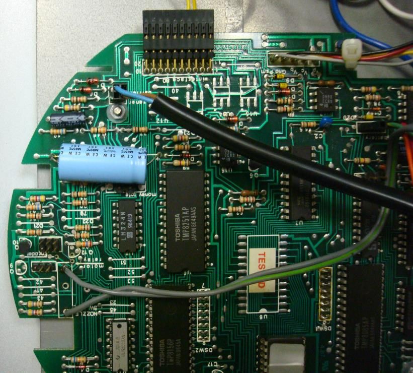
EXAMPLES OF FUEL DISPENSERS CONNECTION SCHEMES
Gallagher (PEC) fuel dispenser connection
Line “ -”
“ +”
Line
Retron 80 dispenser board connection
www.technotrade.ua page 16 from 18NZ INTERFACE CONVERTER TECHNICAL GUIDE
Revision number: 1.03 Review date: 21 March, 2020
Compac dispenser connection
+
-
Compac dispenser junction box
Compac C4000 dispenser board connection
www.technotrade.ua page 17 from 18NZ INTERFACE CONVERTER TECHNICAL GUIDE
Revision number: 1.03 Review date: 21 March, 2020
ORDER INFORMATION
Variant of NZ interface converter supply is marked with NZ4-y-z, where
- y – type of supply:
o “PCB” in case if NZ interface converter is supplied in a view of electric board;
o “BOX” in case if NZ interface converter is supplied installed in plastic box with hermetic inputs
for connection of wires and a button for power supply switching;
- z – variant of supply:
o 001 – variant of supply with installed terminal blocks for controller ports
o 002 – variant of supply without terminal blocks for controller ports (connection is made using
connectors for stubs)
Examples of order:
- order of NZ-4 interface converter in a view of electric board: NZ4-PCB-001;
- order of NZ-4 interface converter installed in a plastic box: NZ4-BOX-001.
www.technotrade.ua page 18 from 18You can also read