EMERSON A9000PX EMERSON SMARTPOWER SOLUTIONS - POWER ADAPTER
←
→
Page content transcription
If your browser does not render page correctly, please read the page content below
Quick Start Guide
                                   MHM-97919-PBF, Rev 1
                                         February 2018

Emerson™ A9000Px

Emerson SmartPower™ Solutions - Power Adapter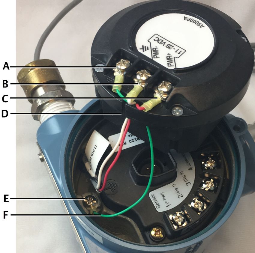
Quick Start Guide                                                                                            February 2018

Copyright
© 2018 by Emerson. All rights reserved.

No part of this publication may be reproduced, transmitted, transcribed, stored in a retrieval
system, or translated into any language in any form by any means without the written permission
of Emerson.

Disclaimer
This manual is provided for informational purposes. EMERSON MAKES NO WARRANTY OF ANY
KIND WITH REGARD TO THIS MATERIAL, INCLUDING, BUT NOT LIMITED TO, THE IMPLIED
WARRANTIES OF MERCHANTABILITY AND FITNESS FOR A PARTICULAR PURPOSE. Emerson shall
not be liable for errors, omissions, or inconsistencies that may be contained herein or for
incidental or consequential damages in connection with the furnishing, performance, or use of
this material. Information in this document is subject to change without notice and does not
represent a commitment on the part of Emerson. The information in this manual is not all-
inclusive and cannot cover all unique situations.

Trademarks and Servicemarks
See http://www.emerson.com/documents/automation/40816.pdf.

All other marks are property of their respective owners.

Patents
The product(s) described in this manual are covered under existing and pending patents.

Contents
Introduction ................................................. 3   Technical data ............................................ 11
Installation requirements ..............................4          Product certifications ..................................12
Installation examples .................................... 5

2                                                                                                  MHM-97919-PBF, Rev 1
February 2018 Quick Start Guide
1 Introduction
1.1 Emerson A9000P description of intended use
The Emerson A9000P series adapters are available in two versions: Emerson
A9000PA and Emerson A9000PS-A. They allow an Emerson wireless
transmitter to be powered by external DC power. When installed with an
appropriate safety barrier, they can be used in a hazardous location. Barrier
requirements are described in the Emerson A9000Px Quick Start Guide and
installation drawings included with the power adapter.
• Use either version to connect external DC power.
• Use the Emerson A9000PS-A to connect external DC power and up to 2
standard ICP accelerometers with a nominal sensitivity of 100 mV/g.
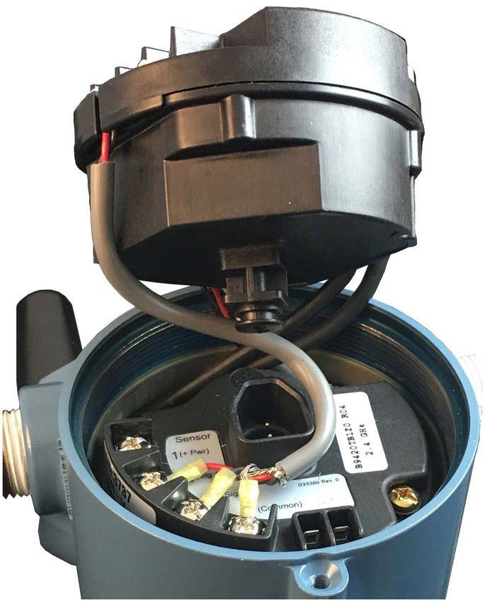
Figure 1-1: Emerson A9000PA (left) and Emerson A9000PS-A (right)
1.2 Optional spacer
The spacer is required only when the transmitter has an extended endcap.
Figure 1-2: Optional spacer
MHM-97919-PBF, Rev 1 3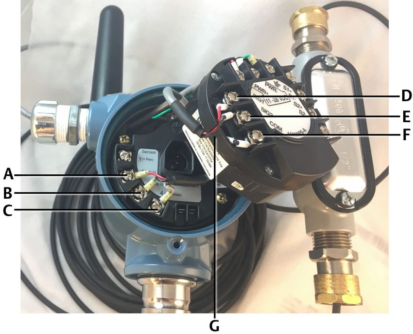
Quick Start Guide                                                          February 2018

2        Installation requirements
2.1      Assembly, location, and mounting requirements
         The Emerson A9000P series adapters use a specially designed connection
         method for insertion into the socket on the termination block used by most
         Emerson wireless transmitters. The adapter is keyed, so that it is only possible
         to insert it in the proper orientation. The adapter must be securely inserted
         into the socket and completely enclosed in the transmitter using an
         appropriate end cap.

         The shorter end cap features a spring-loaded plate which assures that the
         adapter remains securely in place, even when exposed to shock, drop and
         vibration. When using the extended end cap, the provided spacer must be
         inserted into the end cap before installation to maintain a secure connection.

         Power leads, as well as sensor leads where appropriate, enter the rear
         compartment of the transmitter housing through conduit openings on the
         left and right of the housing. Power leads and sensor leads must enter on
         opposite sides of the housing. If sensors leads are not used, the power leads
         may enter on either side of the housing. Emerson recommends the sensor
         leads enter the same side where the sensor terminal screws are located.
         When using two sensors, a 1/2 in. Type T threaded conduit body with cover
         and gasket adapter is required. Always refer to the user documentation of
         the transmitter for installation instructions.

         With the Emerson A9000PS-A, use the included cable harness to jumper the
         signals from the power adapter to the AMS 9420 terminal block. Refer to the
         installation drawing for details. The most recent version of the installation
         drawing is on our website.

2.2      Grounding (protective earthing) requirements
         A grounding screw is provided on the housing of each of Emerson’s wireless
         transmitters as well as on the Emerson A9000P series adapter itself. Refer to
         the user reference documentation for each device for grounding
         requirements or recommendations.

4                                                                   MHM-97919-PBF, Rev 1
February 2018                                                          Quick Start Guide

3        Installation examples
3.1      Connect external DC power to Emerson wireless
         transmitters
         You can use all versions of the Emerson A9000P series adapters to connect
         external DC power to Emerson wireless transmitters. This example describes
         connecting the power adapter. Always refer to the user documentation of
         the transmitter for installation instructions.

                CAUTION!
         DC power should only be applied to the power adapter after it is wired and
         inserted in the transmitter terminal block.

         Procedure

         1. Connect the external DC power to the power adapter.
         2. Connect the included green chassis ground cable to the power adapter
            ground and to the chassis ground point.

             The connections are shown in detail in the installation drawing and an
             example is shown in Figure 3-1.

MHM-97919-PBF, Rev 1                                                                   5
Quick Start Guide                                                        February 2018

             Figure 3-1: External DC power and included cable harness connected
                         to the power adapter

             A. Green chassis ground cable
             B. PWR -
             C. PWR +
             D. Slot
             E. Chassis ground point
             F. Green chassis ground cable

         3. Push each wire through the slot.
         4. Insert the power adapter into the receptacle on the transmitter terminal
            block.
         5. If the transmitter has an extended end cap, insert the spacer into the end
            cap. Otherwise, the spacer is not required.

6                                                                 MHM-97919-PBF, Rev 1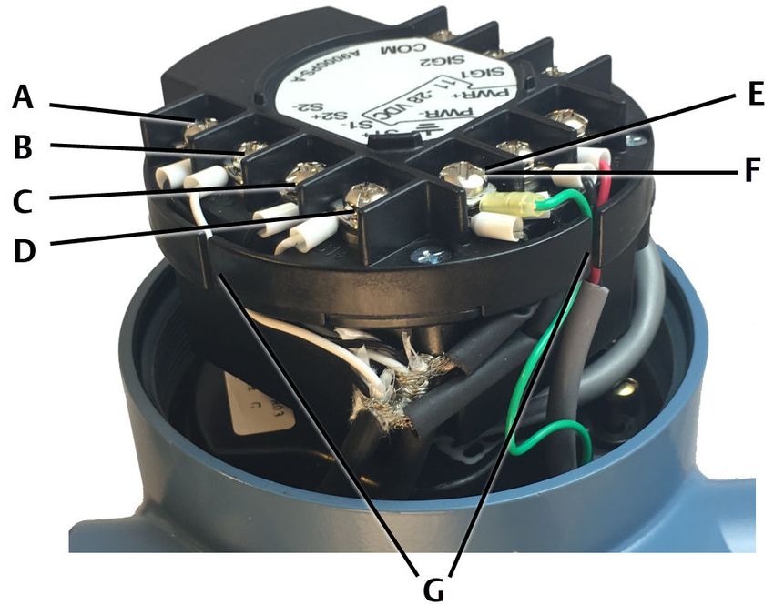
February 2018                                                          Quick Start Guide

                                                        ®
3.2      Connect external DC power and ICP accelerometer
         inputs to an AMS 9420
         With the AMS 9420, use the Emerson A9000PS-A to connect external DC
                                       ®
         power and up to 2 standard ICP accelerometers with a nominal sensitivity of
         100 mV/g. This example describes connecting the power adapter. Always
         refer to the user documentation of the transmitter for installation
         instructions.

         Note
         For a typical AMS 9420 installation, only connect external DC power to the
         power adapter. Low-power accelerometers connect directly to the
         transmitter terminal block.

                CAUTION!
         DC power should only be applied to the power adapter after it is wired and
         inserted in the transmitter terminal block.

         Prerequisites

         Connect external DC power and green chassis ground cable to the power
         adapter. Refer to the example in Section 3.1.

         Procedure

         1. Use the included cable harness to connect the power adapter sensor
            terminals to the AMS 9420, as shown in the installation drawing.

             The cable harness has three wires: two colored wires and one bare wire.
             Each wire has a spade lug on one end and a ferrule on the other end.
             Connect the spade lugs to the terminal block. Connect the ferrules to the
             power adapter. Be careful to connect each wire to the matching terminal
             screw. The connections are shown in detail in the installation drawing and
             an example is shown in Figure 3-2.

MHM-97919-PBF, Rev 1                                                                   7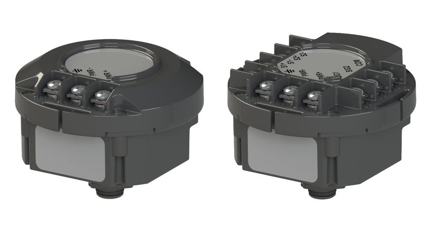
Quick Start Guide                                                                     February 2018

             Figure 3-2: Emerson A9000PS-A to AMS 9420 signal connections
                         with included cable harness

                                                                        Ferrule to Emerson
                    Spade lug to AMS 9420   Cable harness wire          A9000PS-A
               A    2 (Sig 1)               color 1 (red shown)         SIG1                   D
               B    3 (Sig 2)               color 2 (black shown)       SIG2                   E
               C    4 (Common)              unshielded                  COM                    F
               G    Slot

         2. Push each wire from the cable harness into the slot. It is easier to push the
            individual wires into the slot after connecting the ferrules.
                                                                    ®
         3. Connect the leads from up to two standard ICP accelerometers with a
            nominal sensitivity of 100 mV/g to the terminal screws on the Emerson
            A9000PS-A.

8                                                                              MHM-97919-PBF, Rev 1
February 2018                                                      Quick Start Guide

                                  ®
             Figure 3-3: Two ICP accelerometers connected to the power
                         adapter (rotated view)

             A. S2-
             B. S2+
             C. S1-
             D. S1+
             E. S1 Shield
             F. S2 Shield
             G. Slots

         4. Push each signal cable wire into the slot.
         5. Wrap the cable harness counter clockwise around the receptacle on the
            transmitter terminal block.

MHM-97919-PBF, Rev 1                                                                9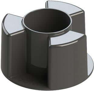
Quick Start Guide                                                        February 2018

             Figure 3-4: Cable harness wrapped around the receptacle

         6. Insert the power adapter into the receptacle.
         7. If the transmitter has an extended end cap, insert the spacer into the end
            cap. Otherwise, the spacer is not required.

10                                                                MHM-97919-PBF, Rev 1
February 2018 Quick Start Guide
4 Technical data
Table 4-1: Environmental conditions
Pollution degree Category 2
Installation category Category II
Altitude 2000 m max.
Operating Temperature -40 to +80° C
Table 4-2: Power specifications
Input power (nominal) 11-28 VDC
Output power (nominal) 7 VDC
Table 4-3: Sensor specifications (P9000PS-A)
Supported sensor type ICP accelerometer
Input signal 100 mV/g
Output signal 25 mV/g
MHM-97919-PBF, Rev 1 11Quick Start Guide February 2018
5 Product certifications
The most recent product certification information is available on our website.
5.1 Approved manufacturing locations
Emerson
835 Innovation Drive
Knoxville, TN 37932 USA
T: +1 865-675-2400
Benchmark Electronics (Thailand) Plc.
109 moo.4, Chaimongkol, Muang, Nakorn Ratchasima
Thailand 30000
T: +66 44-233-800
5.2 European directive information
A copy of the EU Declaration of Conformity can be found at the end of the
Quick Start Guide. The most recent revision of the EU Declaration of
Conformity can be found at www.emerson.com.
5.2.1 ATEX directive (2014/34/EU)
Emerson complies with the ATEX Directive.
5.2.2 Electro Magnetic Compatibility (EMC) (2014/30/EU)
Emerson complies with the EMC Directive.
5.3 Ordinary location certification
The power adapter has been examined and tested to determine that the
design meets the basic electrical, mechanical, and fire protection
requirements.
12 MHM-97919-PBF, Rev 1February 2018 Quick Start Guide
5.4 Hazardous locations certifications
Table 5-1: Emerson A9000PA: Hazardous locations certifications
USA/Canada Certificate CSA17CA70101643X
Marking Class I, Div. 1, Groups A, B, C & D, T4
Class II, Div. 1, Group E, F & G
Class I, Zone 0, A/Ex ia IIC T4 Ga
Standards C22.2 No 61010-1-12; UL 61010-1 3rd Ed.
C22.2 No 60079-0: 2015; UL 60079-0 6th Ed.
C22.2 No 60079-11: 2014; UL 60079-11 6th Ed.
Europe Certificate Sira 17ATEX2323X
Marking
II 1G Ex ia IIC T4 Ga
Standards EN 60079-0:2012/A11: 2013
EN 60079-11:2012
International Certificate IECEx CSA 17.0038X
Marking Ex ia IIC T4 Ga
Ta: -40°C to +85°C
Standards IEC 60079-0:2011 (6th Edition)
IEC 60079-11:2011 (6th Edition)
Table 5-2: Emerson A9000PS-A: Hazardous locations certifications
USA/Canada Certificate CSA17CA70101643X
Marking Class I, Div. 1, Groups C & D, T4
Class I, Div. 2, Groups A, B, C & D, T4
Class I, Zone 0, A/Ex ia IIB T4 Ga
Class I, Zone 2, A/Ex ic IIC T4 Gc
Standards C22.2 No 61010-1-12; UL 61010-1 3rd Ed.
C22.2 No 60079-0: 2015; UL 60079-0 6th Ed.
C22.2 No 60079-11: 2014; UL 60079-11 6th Ed.
Europe Certificate Sira 17ATEX2323X, Sira 17ATEX4375X
Marking
II 1G Ex ia IIB T4 Ga
II 3G Ex ic IIC T4 Gc
Standards EN 60079-0:2012/A11:2013
EN 60079-11:2012
International Certificate IECEx CSA 17.0038X
Marking Ex ia IIB T4 Ga
Ex ic IIC T4 Gc
Ta: -40°C to +85°C
Standards IEC 60079-0:2011 (6th Edition)
IEC 60079-11:2011 (6th Edition)
MHM-97919-PBF, Rev 1 13Quick Start Guide February 2018
5.5 Connections and entity parameters
Entity parameters
Refer to the installation drawing for details. The most recent version of the
installation drawing is on our website.
When the power adapter is installed in a hazardous location, the appropriate
safety barrier is required.
• I.S. Barrier [Ex ia Ga] IIB: 28V, 164Ω, 170mA
• I.S. Barrier [Ex ia Ga] IIC: 28V, 234Ω, 120mA
Refer to the user documentation of the transmitter for details.
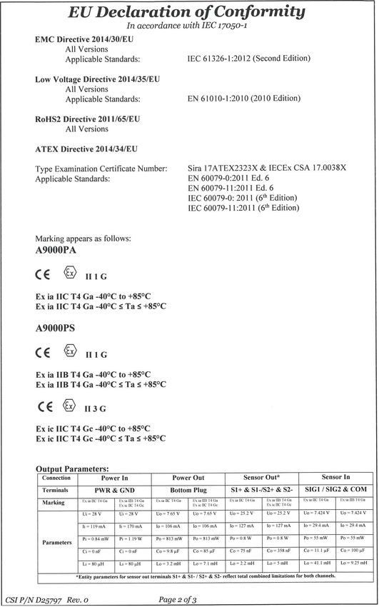
Table 5-3: Entity parameters for power
Connection Power In Power Out
Terminals PWR and GND Bottom Plug
Marking Ex ia IIC T4 Ga Ex ia IIB T4 Ga Ex ia IIC T4 Ga Ex ia IIB T4 Ga
Ex ic IIC T4 Gc Ex ic IIC T4 Gc
Parameters Ui = 28 V Ui = 28 V Uo = 7.65 V Uo = 7.65 V
Ii = 120 mA Ii = 170 mA Io = 106 mA Io = 106 mA
Pi = 0.84 W Pi = 1.19 W Po = 813 mW Po = 813 mW
Ci = 0 nF Ci = 0 nF Co = 9.8 µF Co = 85 µF
Li = 80 µH Li = 80 µH Lo = 3.2 mH Lo = 7.1 mH
Table 5-4: Entity parameters for sensor
Connection Sensor Out(1) Sensor In
Terminals S1+ & S1- / S2+ & S2- SIG1 / SIG2 & COM
Marking Ex ia IIC T4 Ga Ex ia IIB T4 Ga Ex ia IIC T4 Ga Ex ia IIB T4 Ga
Ex ic IIC T4 Gc Ex ic IIC T4 Gc
Parameters Uo = 25.2 V Uo = 25.2 V Uo = 7.424 V Uo = 7.424 V
Io = 127 mA Io = 127 mA Io = 29.4 mA Io = 29.4 mA
Po = 0.8 W Po = 0.8 W Po = 55 mW Po = 55 mW
Co = 75 nF Co = 358 nF Co = 11.1 µF Co = 100 µF
Lo = 2.2 mH Lo = 5 mH Lo = 41.1 mH Lo = 92.5 mH
(1)Entity parameters for sensor out terminals S1+ & S1- / S2+ & S2- reflect total combined limitations for both
channels.
14 MHM-97919-PBF, Rev 1February 2018 Quick Start Guide
Special Condition for Safe Use (X)
The plastic enclosure may constitute a potential electrostatic ignition risk and
caution should be used when being handled. This condition of use does not
apply after a power adapter is installed within a wireless transmitter
enclosure.
Compatibility
The power adapter is compatible with most other Emerson wireless
transmitters that use a power module. It has been certified intrinsically safe
as indicated here; however, always refer to the individual certification
requirements for each product to determine whether it is suitable for
installation and in which environments.
List of critical failures
Not specified
Special conditions for safe use
Do not operate the unit if there is any damage to housing, cover, or rubber
seals.
Special training requirements for personnel
Review operating instructions and certification documentation. Device
should be verified as appropriate for installation in the intended environment
by the safety officer responsible for the end use location.
MHM-97919-PBF, Rev 1 15Quick Start Guide February 2018 5.6 Declaration of Conformity 16 MHM-97919-PBF, Rev 1
February 2018          Quick Start Guide

MHM-97919-PBF, Rev 1                 17
Quick Start Guide         February 2018

18                  MHM-97919-PBF, Rev 1
February 2018          Quick Start Guide

MHM-97919-PBF, Rev 1                 19
Quick Start Guide
                                                      MHM-97919-PBF, rev. 1
                                                            February 2018

Emerson                   ©2018, Emerson.
835 Innovation Drive      All rights reserved. The Emerson logo is a
Knoxville, TN 37932 USA   trademark and service mark of Emerson Electric Co.
T +1 865-675-2400         All other marks are property of their respective
F +1 865-218-1401         owners.
www.Emerson.com           The contents of this publication are presented for
                          informational purposes only, and while every effort
                          has been made to ensure their accuracy, they are
                          not to be construed as warranties or guarantees,
                          express or implied, regarding the products or
                          services described herein or their use or
                          applicability. All sales are governed by our terms
                          and conditions, which are available on request. We
                          reserve the right to modify or improve the designs
                          or specifications of our products at any time
                          without notice.
You can also read