Irish Ergonomics Review 2017 Proceedings of the Irish Ergonomics Society Annual Conference 2017 - IHFES
←
→
Page content transcription
If your browser does not render page correctly, please read the page content below
Irish Ergonomics Review 2017

       Proceedings of the Irish Ergonomics Society Annual
                        Conference 2017
                         DIT Grangegorman Campus Dublin

ISSN 1649‐2102

Edited by Leonard W. O’Sullivan & M. Chiara Leva
Published by the Irish Ergonomics Society
Copyright © The Authors, The Editors, The Irish Ergonomics Society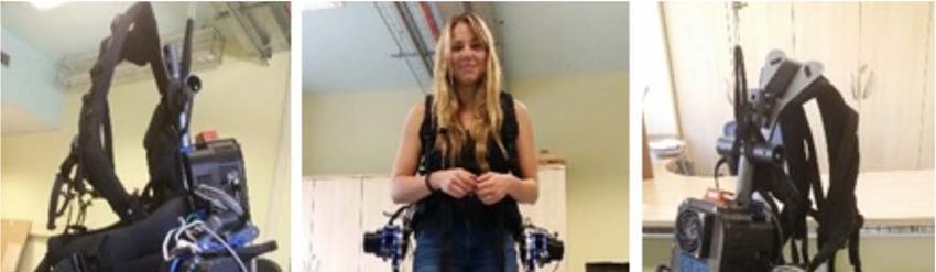
Paper title and authors                                                                          Page

Assessment of an industrial exoskeleton for lifting tasks:                                       1

Kirsten Huysaman and Leonard O’Sullivan, University of Limerick

The application of 3D printing to create high‐fidelity anatomical models for physical surgical   14
simulators:

Kevin O’Sullivan, Louise Kiernan and Leonard O’Sullivan, University of Limerick

Carpal Tunnel Syndrome’s Cyberpsychological Advancement:                                         25

Stella Marie Rostkowski, Walden University, USA

Observation methods to measure psychosocial work risk factors: A synopsis:                       44

Birgit Greiner, University College Cork

Invited IES Keynote lecture

The impact of Court of Appeal Judgements on Damages in Personal Injury Cases and Sentencing in   53
Health and Safety Prosecutions:

Herbert Mulligan, Health and Safety Review

Assessment of an active industrial exoskeleton to aid
                 dynamic lifting and lowering manual handling tasks

                      Kirsten Huysamen*, Michiel de Looze**, Tim Bosch**,

                    Jesus Ortiz***, Stefano Toxiri *** and Leonard O’Sullivan*

       * School of Design, Health Research Institute, University of Limerick, Limerick, Ireland

                        ** TNO, Schipholweg 77, 2316ZL Leiden, The Netherlands

   *** Instituto Italiano di Tecnologia, Department of Advanced Robotics, Via Morego 30, 16163
                                            Genova, Italy

                                              Abstract
      The aim of this study is to evaluate the effect of an industrial exoskeleton on muscle
      activity, perceived physical exertion, measured and perceived contact pressure at the
      trunk, thighs and shoulders, and subjective usability for cyclical lifting and lowering.
      Twelve male participants lifted and lowered a box of 7.5kg and 15kg, respectively, from
      mid‐shin height to waist height, five times, both with and without the exoskeleton. The
      device significantly reduced muscle activity of the Erector Spinae (12%‐15%) and Biceps
      Femoris (5%). Ratings of physical exertion in the trunk region were significantly less with
      the device (9.5%‐11.4%). The measured contact pressure was highest on the trunk
      (91.7kPa‐93.8kPa) and least on shoulders (47.6kPa‐51.7kPa), whereas pressure was
      perceived highest on the thighs (35‐44% of Max LPP). Seven of the users rated the
      device usability as acceptable. The exoskeleton reduced musculoskeletal loading on the
      lower back and assisted with hip extensor torque during lifting and lowering. Contact
      pressures fell below the Pain Pressure Threshold. Perceived pressure was not
      exceptionally high, but sufficiently high to cause discomfort if used for long durations.

1 Introduction
Manual handling activities are associated with high rates of Work‐Related Musculoskeletal Disorders
(WMSDs) (Zurada, 2012, Collins and O’Sullivan, 2015). Despite the widespread use of robots,
automation, mechanisation and work‐related interventions in industry, many tasks are still
performed manually by workers. In some jobs, workers are necessary to perform the work when it
comes to observation and decision‐making, and in other instances tasks benefit from human
precision, skill and movement capabilities (Bos et al., 2004; Zurada, 2012, de Looze et al., 2015).
Hence, despite increased automation, many jobs still require workers to perform manual handling
tasks.
There is a growing interest in industry towards the use of wearable sensors and robotics
technoloiges, including exoskeletons, to assist workers with performing manual handling activities
(de Looze et al., 2015). The principle of an exoskeleton is to add mechanical power to the human
body, thereby reducing the biomechanical load and reducing risk of WMSDs. Exoskeletons are
typically classified as active or passive. Active systems comprise of one or more actuators to

                                                                                                    1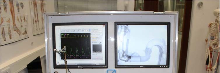
augment the human’s power, whereas passive systems use material compliance to provide gravity
compensation, and spring/elastic members to store and release energy during movements to assist
workers to perform physical movements (de Looze et al., 2015; Matthew et al., 2015). Exoskeletons
are also defined based on the fit and resemblance to the human body limbs. Anthropomorphic
exoskeletons have joints with rotational axes aligned with the rotational movements of the major
human joints, which is not the case with non‐anthropomorphic types (de Looze et al., 2015).
Commercially available exoskeletons have been predominately developed for rehabilitation
purposes, where the devices are aimed to support and assist physically weak, injured or disabled
people with prescribed exercises and activities (Viteckova et al., 2013). A relatively small number of
exoskeletons have been designed for military applications to enhance muscular strength and
physical carrying capacity of soldiers (Anam and Al‐Jumaily, 2012; Yan et al., 2015). Active industrial
exoskeletons are remain mainly at research and development stage while passive exoskeletons have
already entered the market. It is necessary for these technologies, particularly active exoskeletons,
to demonstrate efficacy and safety in order to support their commercial opportunity and uptake in
industry (de Looze et al., 2015).
Manual lifting has been well established as an occupational risk factor for back WMSDs (Zurada,
2012). While the objective of an industrial exoskeleton is to provide assistive power to the worker to
reduce the risks in the work, the device must also have sufficient usability to be comfortable to use,
so that workers accept and are willing to adopt the technology. Studies on exoskeleton prototypes
have shown that they do not always achieve their objectives initially, by failing to meet the needs of
the end users or stakeholders (Almenara et al., 2017). Nonetheless, the basic principle of providing
biomechanical assistance has been proven, but sometimes with increased loading elsewhere in the
body. For instance, the BNDR, HappyBack and Bendezy exoskeletons have been demonstrated to
reduce erector spinae muscle activity by 21‐31% but increase leg muscle activity (Barret and
Fathallah, 2001).
A key factor affecting exoskeleton acceptance is local discomfort caused by the force applied to the
body at the exoskeleton interface (contact pressure). If not carefully designed, the user may
experience significant discomfort and possibly injury, which no doubt will lead lead to reluctance to
use the device. There have been few studies of local discomfort and Pain Pressure Treshold (PPT) on
exoskeletons.
The purpose of the current study was to perform an ergonomics assessment of an exoskeleton
aimed to provide mechanical assistance to the body during lifting tasks to reduce WMSD risk of the
back, while also aiming to minimise discomfort and contact pressure. The exoskeleton tested was
developed as part of the EU‐funded project Robomate (www.robo‐mate.eu). Specifically, the
objectives were to assess the effect of the exoskeleton on muscle activity, physical exertion, contact
pressure, local perceived pressure and subjective usability for short duration cyclical lifting and
lowering.

2 Method
2.1 Participants and ethics approval
Twelve healthy male participants with no prior or current injuries/musculoskeletal disorders gave
written consent to participate in the study (Means & SD: Age: 27 years ± 2, Mass: 75.38kg ± 10.1,
Stature: 1794mm ± 6.56). However, one of these participants was unable to complete the
experiment, resulting in the exclusion of these data.
This study was performed in accordance with the Research Ethics Procedures of the Italian Institute
of Technology, where the testing occurred.

                                                                                                     2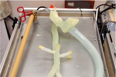
2.2 Experimental design
The independent variables were LOAD (7.5kg and 15kg) and SYSTEM (with/without exoskeleton).
The dependent variables were muscle activity (EMG: Rectus Abdominis, Erector Spinae at level of L3
vertebrae, Biceps Femoris) and perceived physical exertion. Additionally, contact pressure, perceived
musculoskeletal pressure and usability were assessed for the ‘with exoskeleton’ conditions.
There were four treatments (LOAD X 2, SYSTEM X 2) in a full factorial design, which were performed
by each participant in a randomised order (for LOAD and SYSTEM). The treatments involved lifting
and lowering a box from mid‐shin height to waist height five times.
2.3 Procedure
On entering the laboratory, participants were informed of the testing procedure and equipment
involved. At that point anthropometric measurements were obtained followed by the preparation
and attachment of the EMG electrodes on the muscles. After a detailed explanation, demonstration
and setup of equipment (relative to participants’ shin and waist) by the lead investigator,
participants first practiced the lifting task. Testing commenced once participants were proficient and
comfortable with the testing requirements and procedure. The pressure mats were positioned at the
three regions whilst the exoskeleton was being placed on the individual for the ‘with exoskeleton’
conditions.
Each participant performed cyclical lifting and lowering. When they had achieved the required
proficiency level in the movements, they performed five cycles as the experimental run for each
LOAD and SYSTEM treatment. Once experimentation was completed, the participants were required
to perform two MVC measurements per muscle. MVC was conducted at the end to avoid fatigue
prior to testing with the exoskeleton. Each muscle was maximally contracted for three seconds, with
a one‐minute rest period between trials. There was a break of a minimum of five minutes between
treatments.
2.4 Equipment
Testing Equipment
A box (L: 43cm, W: 29cm, H: 16cm) and two loads (7.5kg and 15kg) were used. The box with hand‐
holes was positioned on an adjustable platform set to each participant’s mid‐shin height. The loads
studied reflect a range from moderate to high in industrial tasks, whilst falling within lifting and
lowering guideline weights suggested by Pheasant (2006). Similarly, the origin and destination for
lift/lower were based on guidelines by Pheasant (2006) and ISO standards (ISO 14738:2008).

Exoskeleton
The exoskeleton is an active wearable type aimed to reduce back loading during lifting/lowering
manual handling activities by providing assistive torque at the user’s hip. The exoskeleton is
attached to the trunk and the thighs and articulated to coincide with rotation about the hip region.
The exoskeleton comprises three linked segments: a back unit with two leg units for both thighs
(attachment via Velcro straps). The exoskeleton is worn by the user like a backpack (Figure 1). When
put on, it is adjusted/aligned on the body via a number of straps on the back unit, and then the
attachments at the thighs are secured. The physical assistance is adjusted in real time based on
posture (T=Tmax*sin(angle)) No assistance is provided when the user is standing upright. Before
testing commenced, starting at 20Nm, each participant could adjust the maximum torque ±5Nm.
The adjustability was to assist with comfort and to enable the wearer to vary the power as per their
preference. After this adjustment, the selected torque remained constant throughout the testing
duration.

                                                                                                    3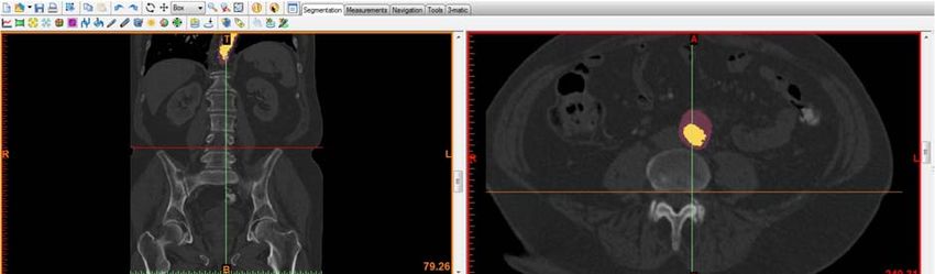
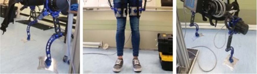
Figure 1 The exoskeleton concept tested

Surface electromyography
Muscle activity of three muscles on the right side of the body was studied: Rectus Abdominis,
Erector Spinae at the level of L3 vertebrae and Biceps Femoris. Data were collected using a portable
NeXus Mark II EMG system (Sampling rate: 2048Hz) with bipolar electrodes placed over each muscle
(inter‐electrode distance: 20mm) as per the guidance in the SENIAM protocol (Hermens et al., 2000).
Nexus Bio Trace software was used to inspect and analyse the data. A ground electrode was placed
on the C7 spinous process. Before electrodes were applied, the skin was shaved, scrubbed and
cleaned with alcohol, again in accordance with the SENIAM protocol (Hermens et al., 2000). A digital
filter was applied to the signals (IIR Band Pass filter Butterworth 3rd Order, 20‐500Hz). The RMS of
the EMG data was calculated to determine the signal amplitudes. Participants performed a
maximum exertion of each muscle group at the end of the experiment. Maximum amplitude
normalised to MVC was determined for the last three lifting and lowering repetitions per treatment.
In the end, data from three participants had to be excluded (giving n = 9 for the EMG data set) as the
data were contaminated, often because electrodes made contact with the exoskeleton during
testing.
Contact pressure
Contact pressure at the interface between the participant and the exoskeleton was measured using
BodiTrak pressure measurement mats, and recorded and analysed using the FSA software supplied.
Three mats were inserted between the exoskeleton and the body on the left side, one proximal to
the shoulder (Shoulder), one at the hip/lower back (Trunk), and one around the upper leg (Thigh).
The sensing area, sensor arrangement and sensor quantity for the Trunk mat was 228mmx228mm,
16x16 array and 256 sensors, and for the Shoulder and Thigh mats were 350mmx350mm, 24x24
array and 567 sensors. Pressure was recorded throughout each treatment. Due to signal
contamination, pressure data from nine participants are reported.

                                                                                                    4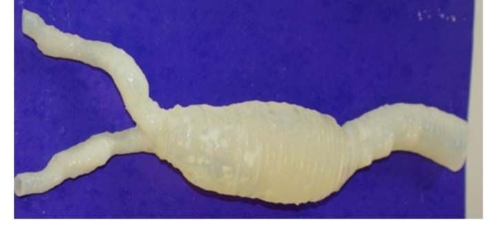
2.5 Subjective responses
Rating of Perceived Exertion (RPE) was rated using the Borg Category Ratio (CR‐10) scale (Borg,
1982). On the left it indicated zero (no physical exertion) and on the right ten (almost maximal
exertion). RPE was assessed for the back and legs separately, for each condition, with and without
the exoskeleton.
Perceived musculoskeletal pressure was rated using the Local Perceived Pressure (LPP) method
(adapted from van der Grinten and Smitt, 1992). LPP was rated on a scale from zero (no pressure at
all) to ten (extremely strong pressure). It was rated for three areas of the body: Back/Shoulders,
Upper Legs and Belly/Hips after each of the two conditions with the exoskeleton.
Usability of the exoskeleton was rated using the System Usability Scale (SUS) (Bangor et al., 2009).
This subjective rating scale consists of ten questions rated from one (strongly disagree) to five
(strongly agree). A score over 70 is deemed acceptable. One participant misinterpreted the
questions due to the language barrier, thus scores of ten participants were reported.

2.6 Data Analysis
All data were analysed using SPSS Statistics Software Version 21, with significance set at p
Table 1: Statistical analysis of maximum %MVC EMG activity for lifting and lowering with and without the exoskeleton for both loads

                     Effects                                                   Conditions
                                           Rectus Abdominis                          ES L3                           Biceps Femoris
                                           7.5kg       15kg                  7.5kg           15kg                   7.5kg     15kg
                    SYSTEM          Z     ‐0.866      ‐0.255              ‐2.701         ‐2.803                     ‐2.701   ‐2.803
                                    P     0.386       0.799                  0.007       0.005                      0.007     0.005
                                           Rectus Abdominis                          ES L3                           Biceps Femoris
                                           W‐ES         ES                   W‐ES             ES                    W‐ES       ES
                     LOAD           Z     ‐2.701      ‐1.784              ‐2.803         ‐2.803                     ‐2.395   ‐2.701
                                    P     0.007       0.074                  0.005       0.005                      0.017     0.007

Figure 2 Maximum percentage MVC for the Rectus Abdominis (left), Erector Spinae (Middle)
and Biceps Femoris (right) for lifting and lowering with (ES) and without (W‐ES) the
exoskeleton for both loads

3.1.2 Rating of Perceived Exertion
The exoskeleton reduced the RPE scores of the trunk by 9.5%/11.4%, and of the legs by 4.5%/8.1%
for the 7.5kg/15kg load respectively (Table 2, Figure 3). This effect was only significant for the trunk
RPE scores (p
Figure 3 Mean perceived physical exertion for lifting and lowering with (ES) and without (W‐
ES) the exoskeleton for both loads

3.2 User assessment of the exoskeleton
3.2.1 Contact pressure
The exoskeleton applied highest pressure to the Trunk region and least on the Shoulder (Figure 4).
Pressure was significantly higher for the thighs and trunk compared to the shoulders (Table 3, Figure
4). Additionally, Shoulder and Thigh pressure was significantly higher for the heavier load. The
pressure applied to the trunk and thighs was on average 91.6kPa /93.6kPa and 69.1kPa/81.2kPa for
the 7.5kg/15kg loads respectively. Contact pressure on the shoulder was approximately 47%/44%
and 30%/36% less than the trunk and thigh pressure for the 7.5kg/15kg loads respectively, where
pressure was on average 48kPa/51.9kPa.
Table 3: Statistical analysis of maximum pressure applied to the human body by the exoskeleton during lifting and lowering for both loads.

                    Effects                                                Conditions
                                                  Trunk                      Shoulder                           Thigh
                     LOAD          Z              ‐0.59                          ‐1.960                        ‐2.197
                                   P              0.953                          0.05                           0.028
                                         Trunk vs. Shoulder               Trunk vs. Thigh              Shoulder vs. Thigh
                                         7.5kg            15kg           7.5kg          15kg           7.5kg            15kg
                     AREA          Z     ‐2.380       ‐2.100            ‐1.352       ‐0.507            ‐2.201       ‐2.201
                                   P     0.017        0.036              0.176          0.612          0.028        0.028

                                                                                                                                        7
Figure 4 Maximum pressure exerted at the trunk, shoulder and thigh by the exoskeleton
during lifting and lowering, for two loads

3.2.3 Local Perceived Pressure
Perceived pressure was higher for the 15kg load than 7.5kg on average across all body regions
(Figure 5). The Upper Legs were rated the highest, with average ratings ‘Somewhat Strong’
(35%/44% of Max LPP for 7.5kg/15kg). The Back/Shoulder and Belly/Hips were rated as ‘Light’
pressure (Figure 5): 25%/28% and 24%/27% of maximum LPP for 7.5kg/15kg respectively.

Figure 5 Mean local perceived pressure (+/‐1sd) for lifting and lowering with the exoskeleton
for two loads

3.2.4 Usability
The System Usability Scores are detailed in Figure 6. Six of the ten participants rated SUS scores
above the criterion for acceptable usability.

                                                                                                     8
Figure 6 Participant SUS ratings of the exoskeleton
4 Discussion
Study of exoskeleton effect on body loading
The key finding of this study was the reduction in muscle activity of the main trunk extending muscle
group in the lower back region, which was in line with the other finding of reduced perceived trunk
exertion. Thus, the exoskeleton reduced musculoskeletal loading on the lower back during the
simulated industrial lifting task. Erector Spinae peak muscle activity at the lumbar level was reduced
by 12‐15%, with a greater reduction in activity for the higher load lifted. As peak muscle activity and
trunk RPE is reduced, the worker’s endurance increases and muscle fatigue decreases, reducing the
risk of developing LBD. Granata et al. (2004) suggests that lower back injuries occur when spinal
loads exceed injury tolerance. In this case the load has been reduced, thereby indicating an
improvement in the user’s injury tolerance, which should in turn help protect spinal structures and
stability.
The results demonstrated that the exoskeleton significantly reduced muscle activity of the Bicep
Femoris by 5%. Thus, the exoskeleton had a large effect on back muscle activity and a marginal
effect on hip extensor activity. Similar findings were previously noted for two passive exoskeletons:
PLAD and Laevo (Bosch et al., 2016).
It was unclear at the outset what the overall net effect on the body would be, especially for the
legs/thighs considering the mass of the exoskeleton and the torque applied at those points. The
results indicated the exoskeleton did not have an effect on perceived leg exertion for either load.
Thus, participants rated the effort of the legs to be similar with and without the exoskeleton, which
is interesting considering the added weight on the user. Furthermore, while RPE was not significant
for the lower limbs for both loads, perceived exertion of the legs was on average less wearing the
exoskeleton than without. This, in conjunction with the reduced Bicep Femoris muscle activity,
indicates the exoskeleton has preferable lower body loading than other exoskeletons, such as BNDR,
HappyBack and Bendezy, which have indications of high lower body loading during use (Barrett and
Fathallah, 2001; Ulrey and Fathallah, 2013).
User assessment of the exoskeleton
The exoskeleton applied highest pressure to the trunk, followed by the thighs, and the least on the
shoulders. Additionally, pressure on the thighs and shoulders increased for the heavier load. This
9trend was also observed in the LLP scores for all three body areas. This result was likely due to the
increased moment and muscle circumference generated by the user to lift the heavier load.
Pain is a warning sign of damage caused by excessive contact pressure, and likewise a good indicator
of potential cell damage and death (Fransson‐Hall and Kilbom, 1993). The point at which a user
begins to feel pain and develops lesions is often referred to as the Pain Pressure Threshold (PPT),
which has been measured as occurring at around 280kPa ‐ 480kPa (Pons, 2008; Tamez‐Duque et al.,
2015). The maximum pressure observed in this study was 93.6kPa, which falls below the PPT levels,
suggesting the device does not pose a problem to workers with regards to pain sensation and tissue
damage, at least in the short‐term (Tamez‐Duque et al., 2015). This was also supported in the LPP
scores where the highest pressure was rated as Somewhat Strong (44% of maximum) for the Upper
Legs and Light for the Back/Shoulders and Belly/Hips. However, it should be noted that LLP was only
measured over five lifting cycles. Unlike contact pressure, we would expect LPP to increase with
longer duration use as would be the case in industry.
In contrast to contact pressure, LLP scores were highest for the upper legs (Somewhat Strong). This
was also observed for the Hybrid Assistive Limb exoskeleton (Nilsson et al., 2014). For both of these
devices, some participants pointed out that the connection cuffs at the thighs were too tight during
use. The circumference of the thigh expands during muscle contraction. This could explain the
increased LPP scores for the thighs. One might expect that we could simply loosen the cuffs.
However, this is not currently feasible with this anthropomorphic exoskeleton as the circumference
of the thigh will continually change during movement and it needs to be securely attached to the
thighs. Thus, at certain stages during the activity the cuffs could be too slack allowing them to alter
their position on the thighs. If this occurs, the force applied to the leg would produce an instability,
thereby resulting in decreased assistance and potential risk of injury. Alternative materials and
attachment solutions should be explored to consider this design challenge.
Even though the LPP scores were not considered excessive, over a longer duration of use they are
expected to increase. Dispersing pressure over a larger area is a common approach to reducing
discomfort in exoskeleton design (Pons, 2008) but this does not entirely resolve the compression
issue and design solutions should again explore ways to also address this challenge. For instance, the
current attachment cuffs comprise single elastic Velcro straps positioned in the middle of the thigh.
Proximal and distal ends of muscles do not expand nearly as much as the central belly. An alternative
could be to have two separate smaller cuffs at either end of a larger cuff with greater flexibility in
the mid‐section. It should be noted that the skin on the upper inner thigh is highly sensitive, thus this
design may cause discomfort if the skin is pinched. Alternatively, the cuffs could comprise of soft
pads. This was implemented on the DGO exoskeleton to prevent pressure sores (Colombo et al.,
2000). Soft pads will, in theory, accommodate muscle size fluctuations during movement.
Backpacks are a common accessory used by individuals daily. This could explain the conflicting
results between contact pressure and LPP scores, as users are familiar with the pressure being
exerted on the back compared to pressure being applied around the thighs. Additionally, the straps
of the back unit comprised soft pads to minimize discomfort. As detailed above, the skin on the
inside and upper thighs is more sensitive than the skin on the trunk, thus pain or discomfort would
be perceived higher (Pons, 2008).
A majority of the participants rated the exoskeleton as having acceptable usability. The users, which
rated the device below the required criterion, found it to be either complex to use, or that at times
the movements were not always completely consistent with their natural movements. From a design
perspective, these factors need to be addressed both through the mechanical and sensor design,
and also in the system software controls, which control the fluidity of the movements.
10Limitations
Due to safety precautions, only five lifting cycles were recorded as the main treatments. This is not a
true reflection of an industrial working day. Now that we know the exposures with the current
design, future testing can include longer duration testing. This will allow for a more accurate
assessment of the interaction between user and device, especially LPP scores. A larger sample size
including experienced manual handling workers is necessary to ascertain the usability of the device
for the working population. Furthermore, females should be assessed, as their body sizes and
capabilities differ to those of males. The assessment of additional muscles, particularly of the lower
limb, should be considered to inform a more complete understanding of the risks. The task
performed was conducted in the sagittal plane. However, in industry, the task may include
asymmetric twisting and walking.
5 Conclusions
The exoskeleton significantly reduced back muscle activity (12%‐15%) and perceived trunk exertion
(9.5%‐11.4%), implying reduced lower back loading. Additionally, the exoskeleton assisted with hip
extensor torque as evidence of the significantly decreased Biceps Femoris muscle activity (5%). To
our knowledge, this exoskeleton is possibly the first active exoskeleton indicating a statistically
significant reduction in Erector Spinae muscle activity in addition to hip extensor assistance for
dynamic lifting and lowering tasks. There was no evidence of increased body loading, in fact the
exoskeleton appears to have preferable lower body loading. Contact pressure values fell below the
PPT, where both discomfort and usability are approaching acceptable levels. In the near future,
wearable sensor and robotics devices, such as this and next generation exoskeletons, have the
potential to be useful tools to assist workers with industrial lifting tasks, especially if assistive torque
is further increased. This study demonstrates the need for strong emphasis on design ergonomics to
ensure such technologies are comfortable and have high usability through their design, in order to
ensure they are suitable and desirable for workers to use.
6 Acknowledgements
This research was performed under the Robomate project (www.robo‐mate.eu) which received
funding from the European Union’s Seventh Framework Programme for research, technological
development and demonstration under grant agreement N° 608979.
7 References
Almenara, M., Cempini, M., Gomez, C., Cortese, M., Martin, C., Medina, J., Vitiello, N. and Opisso, E.
2017. Usability test of a hand exoskeleton for activities of daily living: an example of user‐centred
design, Disability and Rehabilitation: Assistive Technology, 12(1): 84‐96.
Anam, K. and Al‐Jumaily, A.A. 2012. Active exoskeleton control systems: State of the art, Procedia
Engineering, 41: 988‐994.
Barret, A.L. and Fathallah, F.A. 2001. Evaluation of four weight transfer devices for reducing loads on
the lower back during agricultural stoop labor. ASAE meeting, 01‐8056, Sacramento, USA.
Bangor, A., Kortum, P. and Miller, J. 2009. Determining what individual SUS scores mean: Adding an
adjective rating scale, Journal of Usability Studies, 4(3): 114‐123.
Bos, J., Kuijer, P.P.M. and Frings‐Dresen, M.H.W. 2014. Definition and assessment of specific
occupational demands concerning lifting, pushing and pulling based on a systematic literature
search, Occupational and Environmental Medicine, 59, 800‐806.
11Bosch, T., van Eck, J., Knitel, K. and de Looze, M. 2016. The effects of a passive exoskeleton on
muscle activity, discomfort and endurance time in forward bending work, Applied Ergonomics, 54,
212‐217.
British Standard 14738 (BS EN ISO 14738:2008). 2008. Safety of machinery – Anthropometric
requirements for the design of workstations at machinery, BSI, United Kingdom.
Colombo, G., Joerg, M., Schreier, R. and Dietz, V. 2000. Treadmill training of paraplegic patients
using a robotic orthosis, Journal of Rehabilitation Research and Development, 37(6): 693‐700.
Collins, J.D. and O’Sullivan, L.W., 2015, Musculoskeletal disorder prevalence and psychosocial risk
exposures by age and gender in a cohort of office based employees in two academic institutions,
International Journal of Industrial Ergonomics, 46, 85‐97.
De Looze, M.P., Bosch, T., Krause, F., Stadler, K.S. and O’Sullivan, L.W. 2016. Exoskeletons for
industrial application and their potential effects on physical work load, Ergonomics, 59(5), 671‐681.
Enoka, R.M. and Duchateau, J. 2008. Muscle fatigue: what, why and how it influences muscle
function, Journal of Physiology, 586(1): 11‐23.
Fransson‐Hall, C. and Kilbom, A. 1993. Sensitivity of the hand surface pressure, Applied Ergonomics,
24(3): 181‐189.
Granata, K.P., Slota, G.P. and Wilson, S.E. 2004. Influence if fatigue in neuromuscular control of
spinal stability, Human Factors, 46(1): 81‐91.
Hermens, H.J., Freriks, B., Disselhorst‐Klug, C. and Rau, G. 2000. Development of recommendations
for SEMG sensors and sensor placement procedures, Journal of Electromyography and Kinesiology,
10: 361‐374.
Jones, B.H., Bovee, M.W., Harris, J.M. and Cowan, D.N. 1993. Intrinsic risk factors for exercise‐related
injuries among male and female army trainees. American Journal of Sports Medicine, 21: 705‐710.
Macfarlane, G.J., Thomas, E., Papageoriou, A.C., Croft, P.R., Jayson, M.I.V. and Silman, A.J. 1997.
Employment and physical work activities as predictors of future low back pain, Spine, 22: 1143‐1149.
Matthew, R.P., Mica, E.J., Meinhold, W., Loeza, J.A., Tomizuka, M. and Bajcsy, R. 2015. Introduction
and initial exploration of an active/passive exoskeleton framework for portable assistance,
International Conference on Intelligent Robots and Systems, 978‐1‐4799‐994‐1/15, Hamburg,
Germany.
Nilsson, A., Vreede, K.S., Häglund, V., Kawamoto, H., Sankai, Y. and Borg, J. 2014. Gait training early
after stroke with a new exoskeleton – the hybrid assistive limb: a study of safety and feasibility.
Journal of NeuroEngineering and Rehabilitation, 11(92): 1‐10.
Pheasant, S. 1996. Bodyspace: Anthropometry, Ergonomics and the Design of Work, CRC Press,
Lincoln.
Pons, J.L. 2008. Wearable Robots: Biomechatronic Exoskeletons. John Wiley and Sons Ltd: West
Sussex.
Sylla, N., Bonnet, V., Colledani, F. and Fraisse, P. 2014. Ergonomic contribution of ABLE exoskeleton
in automotive industry, International Journal of Industrial Ergonomics, 44: 475‐481.
Taimela, S., Kankaanpaa, S. and Luoto, S. 1999. The effect of lumbar fatigue on the ability to sense a
change in lumbar position‐A controlled study, Spine, 14: 1322‐1327.
12Tamez‐Duque, J., Cobian‐Ugalde, R., Kilicarslan, A., Venkatakrishnan, A., Soto, R. and Contreras‐
Vidal, J.L. 2015. Real‐time strap pressure sensor system for powered exoskeletons, Sensors, 15:
4550‐4563.
Ulrey, B.L. and Fathallah, F.A. 2013. Subject‐specific, whole‐body models of the stooped posture
with a personal weight transfer device, Journal of Electromyography and Kinesiology, 23(1): 195‐205.
Van der Grinten, M.P., Smitt, P. and Kumar, S. 1992. Development of a practical method for
measuring body discomfort, Advances in industrial ergonomics and safety, 4: 311‐318. Taylor and
Francis, London.
Viteckova, S., Kutilek, P and Jirina, M. 2013. Wearable lower limb robotics: A review, Biocybernetics
and Biomedical Engineering, 33, 96‐105.
Yan, T., Cempini, M., Oddo, C.M. and Vitello, N. 2015. Review of assistive strategies in powered
lower‐limb orthoses and exoskeletons, Robotics and Autonomous Systems, 64: 120‐136.
Zurada, J. 2012. Classifying the risk of work related low back disorders due to manual materials
handling tasks, Journal of Expert Systems with Applications, 39, 11125‐11134.
13The application of 3D printing to create high‐fidelity anatomical models for
physical surgical simulators
Kevin J O’Sullivan, Louise Kiernan and Leonard O’Sullivan
School of Design, University of Limerick,
Castletroy, Limerick
Abstract
There is relatively little research on the use of 3D printing to support ergonomics in
healthcare innovation. This current study uses 3D printing to improve the realism of
usability testing during medical device design. Currently, usability testing of
prototype surgical medical devices is often, at best, limited to studies with basic
hollow silicone anatomical models, which are of a single material, and not a direct
resemblance of actual diseased state anatomies. The aim of this research was to
develop an anatomical simulator for early stage usability testing of endovascular
surgical devices using direct replicas of real diseased anatomies from patient scans,
rather than off the shelf basic idealised models. We performed a case study to
recreate a patient’s Abdominal Aortic Aneurysm (AAA) from CT scans. A protocol was
developed to digitally recreate anatomically accurate compound models of the AAA,
to include aortic thrombus and calcifications. The anatomical models were 3D printed
in a range of soft and hard materials, to mimic patient tissues. They were
subsequently integrated into a portable pulsatile flow simulator comprising real‐time
haemodynamic monitoring and a simulated fluoroscopy imaging for usability testing.
1. Introduction
The ultimate goal of any medical device is to improve the well‐being of the person receiving
treatment (Sharples et al. 2012). However, medical technologies often fail to deliver their intended
benefits when they are inadequately designed to match the needs of the intended users (Fairbanks
and Wears 2008). A hospital‐based review by Sarker and Vincent (2005) found that patients were
unintentionally harmed in up to 4% of hospital admissions. Of that cohort, 48% were associated with
a surgical intervention and 54% of these adverse events were deemed preventable. Early stage
Usability Testing (UT) to design robust, safe and effective medical devices has become a significant
focus to reduce the potential for human error.
Measuring and fulfilling user requirements during medical device development results in successful
products that help improve patient safety, improve device effectiveness and reduce product recalls
and modifications (Jennifer et al. 2006). To achieve this, UT is applied from the earliest opportunity
through to validation testing prior to market launch (Alley 2014, FDA 2011). Validation of medical
devices should include laboratory testing to evaluate device efficacy, reliability, safety and
performance before clinical testing begins (Weinger et al. 2010). Early stage UT relies heavily on
simulation using anatomical models under use conditions to explore worst case scenarios, complex
failures and environmental interactions, while validating medical devices (Browne and O’Sullivan
2012).
14Patient simulators are now routinely used to teach medical skills, such as respiratory physiology and
cardiovascular haemodynamics, and also some advanced clinical skills, such as airway management.
There are several augmented reality simulators for minimally invasive endovascular surgery that are
commercially available, including the Mentice Vist G5 and the Angio Mentor. These provide little to
no haptic feedback during testing / training, despite the high cost of the systems. Computer‐based
simulators are generally unsuitable for medical device design evaluation as they cannot test physical
prototypes, which is necessary for design testing purposes.
Endovascular surgery is an example of a branch of medicine that commonly uses minimally invasive
medical devices. Such devices are delivered primarily into and through the vascular system. While
the devices are minimally invasive, it is pertinent that they are designed to ensure safety during use.
For endovascular device evaluation, the most described physical simulators include silicone
anatomical models used in pulsatile flow rigs (Doyle et al. 2008, Ene et al. 2011, Lynch et al. 2013,
Poepping et al. 2004, Chong et al. 1998). A key objective in the design of patient simulators is to
achieve a ‘suspension of disbelief’ by the operator (Halamek et al. 2000). Farmer et al. (1999)
defined ‘fidelity’ as the extent to which the appearance and behaviour of the simulator/simulation
matches that of the desired system. Allen et al. (1991) proposed two dimensions of fidelity:
‘Structural Fidelity’ (how the simulator appears) and ‘Functional Fidelity’ (what the simulator does).
Structural fidelity is the degree to which the simulator or environment replicates the physical
characteristics of the real task. For surgical procedures and medical device testing, structural fidelity
is of very high importance for the task (e.g. when interacting directly with tissue or anatomies).
Functional fidelity is the degree to which the skills in the real task are captured in the simulated task.
The level of functional fidelity required is dependent on the type of task and the level of training of
the user. Silicone anatomical models used in pulsatile flow simulator, exhibit high functional fidelity
in their ability to reproduce physiological conditions, but offer a low level of structural fidelity.
The objectives of the current research were to create replicas of real diseased patient‐specific
anatomies to achieve high functional fidelity, and to then integrate these into a pulsatile flow rig to
achieve a physical simulator that could be used for early stage testing of endovascular medical
devices. To achieve this, we A., recreated anatomical models from patient scans, B., recreated the
models using multi‐material 3D printing, and C., developed a portable usability test bed that uses the
anatomical models and includes real time haemodynamic monitoring and simulated fluoroscopic
imaging.
2. Anatomical segmenting in preparation for 3D printing
Anatomical segmentation is the process of isolating anatomical structures from medical imaging in
order to produce 3D digital models. Compound anatomical models differ from basic hollow silicone
anatomical models in that they can include elements such as thrombus or calcifications to enhance
the structural fidelity during medical device testing or training. To create a compound anatomical
model, it is necessary to segment the individual structures from a set of medical images to prepare
the individual structures reassembled as a single compound model for 3D printing . The individual
isolated parts of the anatomical structures can then be printed with different material properties.
Efforts have been made previously to segment compound anatomical models in the literature for
FEA computer simulations (Wang et al. 2002), however these models contained only two elements.
In the current research we used Mimics software (Research Version 17, Materialise, Belgium) to
create the 3D models of the patient’s anatomy. Anonymised CT scans of a patient with an Abdominal
Aortic Aneurysm (AAA) and another with a healthy aorta were used to create the 3D anatomical
models. The local research ethics committee approved use of the anonymised patient scans.
15By way of example, the AAA model was created in four separate parts: 1. The true lumen, 2.
Aneurysm sac, 3. Calcifications, and 4. Aortic wall. The individual parts were then combined to create
a full model of the internal volume of the AAA, as illustrated in Figure 1. In addition to creating the
compound anatomical models, modifications were made to the models in the Mimics sister software
package 3Matic to attach rigid end ports to join the models to piping in the UT test bed (Figure 2).
The need for compound anatomical models is demonstrated in Figure 3, where the path of the true
lumen is considerably more tortuous in the lower model, which includes thrombus. Basic hollow
silicone anatomical models are not a true representation of the actual anatomy. The sharply
angulated AAA neck, as shown in Figure 3(arrow), would be considered challenging to navigate with
a 16French endovascular device.
3. 3D Printing anatomical models for simulation and training
Traditionally, aortic models for use in pulsatile simulators were made from silicone using the lost
wax method (Doyle et al. 2008). This is a labour intensive method that requires extensive machining
of multiple aluminium moulds. There is a significant time requirement to create the wax core, mount
the core in a secondary mould, and then fill the cavity between both parts with silicone.
Furthermore, the moulding approach is highly susceptible to defects such as air bubbles and uneven
wall thickness.
Recent advances in 3D printing present opportunities to create replicas of human anatomies in
materials with varying durometers from rigid to pliable. There are numerous 3D printing
technologies available today. These include Stereolithography (SLA); curing acrylic or epoxy‐based
resins using a high intensity energy source; Selected Laser Sintering (SLS); laser fusing of fine grade
polymer or metallic powder, Fused Deposition Modelling (FDM), which uses extruded
thermoplastics, and Polyjet printing technology, which is a modified inkjet printing method.
Figure 1: The user interface in the Mimics software while segmenting the model of the Abnormal
Aortic Aneurysm, including the generation of the 3D model (bottom right)
16Figure 2 Model of an aorta attached with rigid connection ports for 3D printing
Figure 3 Cross section of the 3D model of the AAA showing the aorta wall on its own (top) and
including the thrombus (bottom)
17Polyjet printing is amongst the most advanced 3D printing platforms available. It works similar to a
traditional inkjet printer in that two or more materials (inks) can be combined to create a multitude
of secondary materials. The materials can be soft rubber like, rigid and mixed durometer, all within a
single model. The Connex 500 is a polyjet 3D printer that uses two base materials (acrylic monomer
resin) and a water soluble support material cured using high intensity UV light. The two base
materials can be combined to create 14 digital materials with varying mechanical properties. The
ability to print several materials in a single model is ideally suited to this research.
We took the compound anatomical model as shown in Figure 1 and used the Connex digital material
DM_9760 for the aortic wall, TangoPlus for the thrombus and VeroWhite for the calcifications. The
flexible material was based on research indicating it may be a suitable analogue for aortic tissues
(Cloonan et al. 2014). Figure 4 shows the digitally segmented 3D AAA model (top) and the finished,
cleaned 3D printed model (bottom).
A cross section of the digital and printed models demonstrates the material differences. Figure 5
shows the 3D model including the location of the cross section in the middle of the aneurysm (left),
the digital image of the aneurysm cross section (middle), and the cross section of the 3D printed
model showing the arterial wall, thrombus and calcifications (right).
Figure 4 The computer 3D Model of AAA (top) and the 3D Printed Model (bottom)
18Figure 5 The 3D Model of the AAA (L), a cross section of AAA model showing the aortic wall,
thrombus, calcifications, and true lumen (R), and a section of the corresponding 3D printed model
4. Pulsatile flow simulator and vision system
A pulsatile flow simulator was designed into which 3D printed anatomies could be attached for
usability testing or training with endovascular medical devices. A system level diagram for the
simulator is shown in Figure 6. The simulator is a closed loop, to approximate the human
cardiovascular system. The flow loops from a pump through the anatomical model and pressure
control valve back to a heated reservoir. The heart rate and cardiac output (rate of flow) are digitally
controlled through an integrated interface.
The interface simultaneously displays real‐time pressure, flow, and temperature data, as well as a
simulated ECG signal. A second monitor displays a simulated fluoroscopic image. The fully assembled
simulator was built into a padded flight case for portability and can be transported readily by car.
Pulsatile flow is an essential component of any system to be used in the evaluation of endovascular
devices to recreate the mechanical stresses found in the body. A reciprocating piston pump was
used based on the work of Morris et al. (2013). A steel direct drive rack and pinion is powered using
a stepper motor. Two one‐way valves installed in opposite directions to the piston pump manifold
create unidirectional flow. The length of the piston stroke determines the volume of fluid displaced,
creating the required cardiac output. The piston stroke (cardiac output) and frequency (heart rate)
can be adjusted digitally in real time. Systolic pressure is generated by the cardiac output (approx.
80ml/beat) while the diastolic pressure is controlled using the viscoelastic properties of the system.
The anatomical model, tubing, and control valve (distal to the aortic bifurcations) generate sufficient
compliance.
Figure 7 shows a full size 3D printed healthy aortic model in the pulsatile flow simulator (detailed
below). The model includes the left ventricle, aortic arch, descending and thoracic aorta and
bifurcation. All of the main branches of the aorta are included and can be selectively occluded
depending on the devices being tested.
19Figure 6 Schematic drawing of the pulsatile simulator
Pressure in the simulator is measured at multiple locations and displayed on the interface. To
enhance the functional fidelity of the simulator while manipulating devices, a blood analogue
comprising a glycerol and water mix (~44:56 ratio) with sodium chloride (~0.9%) was used (Yousif et
al. 2010). Normal body temperature is maintained at a constant 37°C (+/‐ 0.5°C) by means of a
heated reservoir and thermistor control loop.
The simulator is controlled using a combination of LabView and Arduino platforms. A Virtual
Instrument (VI) was created as the interface to visualise both the input parameters (pump controls)
and output haematological measurements (Figure 8: left screen). The VI was designed to
approximate a typical monitoring screen found in the cath lab. The VI allows adjustment of the input
parameters and monitoring of the outputs in real time.
Simulated fluoroscopy imaging was achieved using a CCD camera, converted to black and white
format and the contrast / brightness adjusted to approximate the image quality of a fluoroscope.
Figure 9 presents a series of on‐screen images of the aortic root arteriogram at three phases of
injecting contrast (black dye) to demonstrate the visualisation.
4. Discussion
3D printing in healthcare has become a useful tool for both visualising complex conditions and
surgical planning (Rengier et al. 2010). The work presented here is a novel use of multi‐material to
improve medical device usability to reduce errors and enhance surgical treatment. A protocol to
digitally segment compound anatomical models was successfully developed and patient‐specific
models were created, which were successfully recreated using multi‐material 3D printing. While the
segmenting of anatomical models is not novel, the segmenting and printing of patient‐specific
20compound models for early stage usability testing does not appear to be previously detailed in the
literature.
Figure 7 Image of a 3D printed aorta in the pulsatile rig
Figure 8 Front view of the endovascular simulator, in this case with a basic silicone anatomical model
shown
21Figure 9 Simulated fluoroscopic image on the simulated fluoroscope image at three stages of
injecting simulated contrast into the aortic root
Several important use case criteria are omitted when testing prototypes in basic hollow anatomical
models, and this in turn can impact the validity of the simulated use testing. The reaction of vessels
(such as the femoral arteries) to straightening cannot be considered valid if the presence of
calcifications is omitted, as in silicone models. The current approach is an important contribution to
improving the fidelity of these models and will advance the realism of usability testing.
The design and use of pulsatile flow simulators is well discussed in the literature (Chong et al. 1998,
Doyle et al. 2008, Morris et al. 2013, Cloonan et al. 2014) but few have been developed for the
purposes of early stage usability testing. Current simulators are generally specific to anatomical
models or disease states. They are generally not portable, are inflexible for use with various
anatomical models, and/or do not physiologically resemble the cardiovascular blood flow. A portable
simulator, as presented, is advantageous as it can be transported to surgical experts with ease of
setup on‐site for testing sessions. Another advantage of the current simulator is the ease of
exchange of multiple anatomical models.
Other advantages of 3D printing anatomical models, over lost wax casting, relate to time and cost.
Due to the large size of the print bed on the Connex 500 3d printer, three patient specific AAA
models were manufactured in a single 26‐hour build period. While the polyjet technology is
relatively expensive, with each model costing circa €500 ‐ €800 in raw material, the costs are not
dissimilar to commercially available hollow silicone models.
The use of real‐time haemodynamic monitoring is novel in the current work over previous pulsatile
flow rigs. Experimentally focused pulsatile flow rigs often measure pressure, flow and temperature.
However, these are often logged rather than presented in real time. The monitor interface, as
created in this work, resembles those in traditional cath‐lab monitoring equipment, and as such,
contributes to the structural fidelity.
Limitations
There are some limitations to the 3D printed materials presented here. As with most 3D printed
materials, there can be weaknesses between the printed layers, which can lead to delamination and
splitting. The TangoPlus material is slightly hydroscopic and overtime absorbs water. This leads to
opacification of the material, and in thin sections, can lead to failure as the material swells and
delaminates. For this reason, the use of pure TangoPlus for the aortic wall, as proposed by Cloonan
et al. (2014), is inappropriate for prolonged use in contact with water. There are also issues with the
22longevity of polyjet materials. As the materials are UV‐cured, they can degrade with time when
exposed to daylight. Experiments are underway to investigate coating the finished 3D printed
models to reduce this.
The quality of CT ‐ DICOM scan images used dictates the quality of the models. For example, the
segmentation of the aortic wall can be difficult for a number of reasons. The wall itself has
comparable properties and density to surrounding tissues and the wall is only 1.3 – 2mm thick,
making it difficult to identify. This challenge can be partly addressed using high resolution scans.
One obvious limitation of the current work is the quality of simulated imaging. The inherent
difficulties of replicating X‐ray imaging is a long standing challenge (Chong et al. 1998). While the
quality of the simulated imaging presented here is inferior to VR simulators such as the Angio Kit or
Mentice Vice, the primary purpose for UT is to avoid ‘direct visualisation’ of the device being tested
in the anatomical model.
A further limitation of the simulated imaging system presented here is that it is continuously live. In
a clinical setting the fluoroscope is only activated briefly at a time to limit the exposure of ionising
radiation. Future development of the current work should include the addition of a foot pedal to
start/stop the ‘fluoroscopic’ image as occurs in the practice.
6. Conclusions
The current research successfully demonstrated the replication of patient‐specific anatomical
models, including the use of 3D printing with multi‐materials, to resemble the mix of hard and soft
aspects of the tissues. These anatomically accurate models advance the realism and therefore
fidelity of usability test simulators.
Any usability test bed for use with endovascular surgical devices should mimic physiological
conditions as closely as possible. Pulsatile flow, physiological pressure and temperature are
important for representative testing of such medical devices. The simulator presented is
anatomically accurate relative to specific disease states, and also physiologically resembles blood
flow, pressure and temperature. The portability of the current simulator, coupled with physiological
and anatomical resemblance to the human anatomy, is an improvement on contemporary simulator
designs. It can be used for UT and also medical device training.
3D printing using Polyjet multi‐materials represents a new paradigm for the production of
anatomical models for usability testing of medical devices. While the work presented here is
primarily focused on usability testing, use of this new approach could extend further into surgical
training, surgical planning, demonstration and other medical experimental applications.
7. Acknowledgements
The authors wish to thank the Irish Research Council for Science, Engineering and Technology
(IRCSET) and the associated industrial partner Design Partners, Bray, Ireland, for supporting this
research.
8. References
Allen, J., Buffardi, L. and Hays, R. (1991) The relationship of simulator fidelity to task and
performance variables, DTIC Document.
Alley, K. I. (2014) Defining the Industrial Designer's Role in the ISO/IEC 62366 Standard, unpublished
thesis University of Cincinnati.
Browne, A. and O’Sullivan, L. (2012) 'A medical hand tool physical interaction evaluation approach
for prototype testing using patient care simulators', Applied Ergonomics, 43(3), 493‐500.
23Chong, C., How, T., Black, R., Shortland, A. and Harris, P. (1998) 'Development of a simulator for
endovascular repair of abdominal aortic aneurysms', Annals of Biomedical Engineering,
26(5), 798‐802.
Cloonan, A. J., Shahmirzadi, D., Li, R. X., Doyle, B. J., Konofagou, E. E. and McGloughlin, T. M. (2014)
'3D‐printed tissue‐mimicking phantoms for medical imaging and computational validation
applications', 3D Printing and Additive Manufacturing, 1(1), 14‐23.
Doyle, Morris, L. G., Callanan, A., Kelly, P., Vorp, D. A. and McGloughlin, T. M. (2008) '3D
Reconstruction and Manufacture of Real Abdominal Aortic Aneurysms: From CT Scan to
Silicone Model', Journal of Biomechanical Engineering, 130(3), 034501‐034501.
Ene, F., Gachon, C., Delassus, P., Carroll, R., Stefanov, F., O’Flynn, P. and Morris, L. (2011) 'In vitro
evaluation of the effects of intraluminal thrombus on abdominal aortic aneurysm wall
dynamics', Medical Engineering & Physics, 33(8), 957‐966.
Fairbanks, R. J. and Wears, R. L. (2008) 'Hazards with medical devices: the role of design', Ann Emerg
Med, 52(5), 519‐21.
Farmer, E., Van Rooij, J., Riemersma, J., Jorna, P. and Moraal, J. (1999) 'Handbook of simulator‐based
training'.
FDA (2011) 'Applying Human Factors and Usability Engineering to Optimize Medical Device Design',
Halamek, L. P., Kaegi, D. M., Gaba, D. M., Sowb, Y. A., Smith, B. C., Smith, B. E. and Howard, S. K.
(2000) 'Time for a New Paradigm in Pediatric Medical Education: Teaching Neonatal
Resuscitation in a Simulated Delivery Room Environment', Pediatrics, 106(4), e45‐e45.
Jennifer, L. M., Elizabeth, M., John, A. C. and Beverley, J. N. (2006) 'Capturing user requirements in
medical device development: the role of ergonomics', Physiological Measurement, 27(8),
R49.
Lynch, B., Nelson, J., Kavanagh, E. G., Walsh, S. R. and McGloughlin, T. M. (2013) 'A Review of
Methods for Determining the Long Term Behavior of Endovascular Devices', Cardiovascular
Engineering and Technology, 5(1), 1‐12.
Morris, L., Stefanov, F. and McGloughlin, T. (2013) 'Stent graft performance in the treatment of
abdominal aortic aneurysms: The influence of compliance and geometry', Journal of
Biomechanics, 46(2), 383‐395.
Poepping, T. L., Nikolov, H. N., Thorne, M. L. and Holdsworth, D. W. (2004) 'A thin‐walled carotid
vessel phantom for Doppler ultrasound flow studies', Ultrasound in Medicine & Biology,
30(8), 1067‐1078.
Rengier, F., Mehndiratta, A., von Tengg‐Kobligk, H., Zechmann, C. M., Unterhinninghofen, R.,
Kauczor, H.‐U. and Giesel, F. L. (2010) '3D printing based on imaging data: review of medical
applications', International Journal of Computer Assisted Radiology and Surgery, 5(4), 335‐
341.
Sarker, S. K. and Vincent, C. (2005) 'Errors in surgery', Int J Surg, 3(1), 75‐81.
Sharples, S., Martin, J., Lang, A., Craven, M., O’Neill, S. and Barnett, J. (2012) 'Medical device design
in context: A model of user–device interaction and consequences', Displays, 33(4–5), 221‐
232.
Wang, D. H. J., Makaroun, M. S., Webster, M. W. and Vorp, D. A. (2002) 'Effect of intraluminal
thrombus on wall stress in patient‐specific models of abdominal aortic aneurysm', Journal of
Vascular Surgery, 36(3), 598‐604.
Weinger, M. B., Wiklund, M. E. and Gardner‐Bonneau, D. J. (2010) Handbook of human factors in
medical device design, CRC Press.
Yousif, M. Y., Holdsworth, D. W. and Poepping, T. L. (2010) 'A blood‐mimicking fluid for particle
image velocimetry with silicone vascular models', Experiments in Fluids, 50(3), 769‐774.
24You can also read