ISEEYOU: DISABLING THE MACBOOK WEBCAM INDICATOR LED - MATTHEW BROCKER AND STEPHEN CHECKOWAY, JOHNS HOPKINS UNIVERSITY
←
→
Page content transcription
If your browser does not render page correctly, please read the page content below
iSeeYou: Disabling the MacBook
                Webcam Indicator LED
     Matthew Brocker and Stephen Checkoway, Johns Hopkins University
https://www.usenix.org/conference/usenixsecurity14/technical-sessions/presentation/brocker

         This paper is included in the Proceedings of the
                23rd USENIX Security Symposium.
                        August 20–22, 2014 • San Diego, CA
                                  ISBN 978-1-931971-15-7

                                                Open access to the Proceedings of
                                              the 23rd USENIX Security Symposium
                                                     is sponsored by USENIX
iıSeeYou: Disabling the MacBook
                                         Webcam Indicator LED
                            Matthew Brocker                             Stephen Checkoway
                         Johns Hopkins University                     Johns Hopkins University

Abstract
The ubiquitous webcam indicator LED is an important
privacy feature which provides a visual cue that the cam-                              (a) Image sensor (front)
era is turned on. We describe how to disable the LED on
a class of Apple internal iSight webcams used in some
versions of MacBook laptops and iMac desktops. This
enables video to be captured without any visual indication                             (b) Image sensor (back)
to the user and can be accomplished entirely in user space
by an unprivileged (non-root) application.
   The same technique that allows us to disable the LED,
namely reprogramming the firmware that runs on the                                      (c) Main board (front)
iSight, enables a virtual machine escape whereby malware
running inside a virtual machine reprograms the camera
to act as a USB Human Interface Device (HID) keyboard
which executes code in the host operating system.                                       (d) Main board (back)
   We build two proofs-of-concept: (1) an OS X applica-
tion, iSeeYou, which demonstrates capturing video with                 Figure 1: The iSight from a 2008 MacBook we studied.
the LED disabled; and (2) a virtual machine escape that
launches Terminal.app and runs shell commands. To de-
fend against these and related threats, we build an OS X               The value of video evidence is so high that The Wash-
kernel extension, iSightDefender, which prohibits the               ington Post recently reported that the US Federal Bureau
modification of the iSight’s firmware from user space.              of Investigation (FBI), has developed surveillance mal-
                                                                    ware, similar to the proof-of-concept described in this
1    Introduction                                                   paper, which can covertly turn on a victim’s webcam [59].
Video is ineffably compelling. The (consensual) shar-               Of course, the threat to privacy from webcams vulnerable
ing of video is an act of intimacy as it allows the viewer          to hacking comes not only from law enforcement.
a glimpse into the life of the sharer. It is no surprise               At the beginning of the 2008 school year, the Lower
then that the Internet’s first “lifecast,” Jennifer Ringley’s       Merion School District provided a MacBook laptop to
“JenniCam” in 1996 [24], was video and not audio. Simi-             each enrolled student. These laptops came pre-loaded
larly, YouTube, the most popular website for sharing user-          with the LANrev remote administration tool (RAT) which
created videos, predates SoundCloud, a website with sim-            allowed school district officials to, among other things,
ilar functionality for audio, by several years even though          capture images from the MacBooks’ built-in iSight web-
technological constraints would suggest the opposite or-            cam. During the following 18 months, officials captured
der. It is precisely because of the intimacy of video that          more than 30 thousand images from these webcams [5, 6].
turning on someone’s camera without his or her knowl-               The first indication that images were being captured was
edge or consent is a violation more fundamental than                every time the software took a picture, the green indicator
recording audio.                                                    LED would briefly illuminate [5, 6, 42]. Some teachers
   Beyond intentional sharing, video makes for more                 were so concerned by this they they covered the lens of
compelling evidence that an event occurred as claimed               the webcams on their own laptops [6]. Here, the indicator
than either an after-the-fact eye witness account or audio          LED worked exactly as it was supposed to and alerted the
recording. This is true whether it is a video of a suc-             users that they were being photographed.
cessfully performed feat of skill — e.g., in sports [44] or            The possibility that a webcam could be capturing pic-
even video games [49] — video of police brutality [55],             tures without the LED illuminating has led to suggestions
video of violent crime [63], or webcam video used for               that owners should tape over the webcam [43] as well as
blackmail [15].                                                     products designed to cover the camera stickers [10, 58].

                                                                1
USENIX Association                                                                     23rd USENIX Security Symposium 337
This incident illustrates the dangers of passive sensors             user space application, iSeeYou, to do so (Section 6).
attached to computers like cameras, microphones, and                  3. We demonstrate how to use the capability developed
GPS receivers. Unlike active input devices like keyboards                to bypass the hardware interlock to achieve a virtual
and mice that require user actions to provide input, a pas-              machine escape (Appendix A1 ).
sive sensor requires no action on the part of the user to             4. We develop an OS X kernel extension, iSightDe-
capture input. Indeed, a user is typically unaware that                  fender, to defend against these attacks (Section 7).
input is being captured at all unless specific mechanisms             5. We sketch the design space for building a secure
are built into the technology to indicate that the sensor is             camera module (Section 8).
currently in use. Such mechanisms include camera-use in-               The ability to bypass the interlock raises serious pri-
dicator LEDs, shutter sounds on cell phone cameras, and             vacy concerns and the technical means by which we ac-
GPS-use indicator icons on mobile devices and laptops.              complish it raises additional security concerns which we
    In the past few years, the ever-expanding set of sen-           discuss in Section 9.
sors present in commodity laptops and smart phones has              Threat model. To mount our main attack where we cap-
prompted the security and privacy community to begin                ture video without any external indication to the victim,
researching ways to detect and limit the undesired use of           we assume that an attacker is able to run native code on
sensors [20, 22, 26, 27, 31]. At the same time, researchers         the victim’s computer as an unprivileged user. Further,
have demonstrated attacks exploiting the presence of sen-           we assume the code is unencumbered by defenses such
sors such as a clickjacking attacks against Adobe Flash             as Apple’s App Sandbox [4] which is used for applica-
to gain access to the camera and microphone [23] from               tions downloaded from the Mac App Store but by little
a malicious web page and exfiltrating audio from micro-             else. This assumption is quite mild and would typically
phones in modern automobiles [11]. (See Section 2 for               be satisfied by malware such as RATs.
more examples.)                                                        For the virtual machine escape, we assume the attacker
    Our results in this paper demonstrate that, at least in         has code running locally in the virtual machine and with
some cases, people have been correct to worry about mal-            whatever privileges the guest OS requires to communi-
ware covertly capturing images and video. We show a                 cate with USB devices. We also assume that the virtual
vulnerability in the iSight webcam that affects a particu-          machine monitor has exposed the iSight device to the
lar range of Apple computers — including the MacBooks               virtual machine. This second assumption is quite strong
given to the students in the Lower Merion School Dis-               as virtual machine monitors typically do not expose USB
trict — that can be exploited to turn on the camera and             devices to the guest OS unless the user specifically con-
capture images and video without the indicator illuminat-           figures it to do so, for example to use video conferencing
ing.                                                                software.
    At a high level, our investigation of the iSight revealed
that it is designed around a microprocessor and a sepa-             Generality of results. We stress that our main result —
rate image sensor with an indicator LED sitting between             disabling the iSight LED — only applies to the first gen-
them such that whenever the image sensor is transmit-               eration internal iSight webcams, found in some Apple
ting images to the microcontroller, a hardware interlock            laptops and desktops, and we make no claims of security
illuminates the LED. We show how to reprogram the mi-               or insecurity of later models, including the most recent
crocontroller with arbitrary, new firmware. This in turn            (renamed) FaceTime cameras. The virtual machine es-
enables us to reconfigure the image sensor, allowing us to          cape described in Appendix A likely holds for other USB
bypass the hardware interlock and disable the LED. We               devices that use the Cypress EZ-USB chip used in the
also show a new method of performing a virtual machine              iSight, but we have not yet tested other devices.
escape based on our ability to reprogram the microcon-              2    Related work
troller.
    Specifically, our technical contributions in this paper         General purpose computers contain a variety of proces-
are five-fold:                                                      sors designed for performing specialized tasks other than
   1. We describe the architecture of the Apple internal            general-purpose computation. Examples include graph-
      iSight webcam found in previous generation Apple              ics processing units (GPUs) which produce video output;
      products including the iMac G5 and early Intel-based          processors in network interface controllers (NICs) which
      iMacs, MacBooks, and MacBook Pros until roughly               perform network packet processing; microcontrollers in
      2008 (Section 3).                                             perhipherals such as keyboards, mice, and webcams; mi-
   2. We demonstrate how to bypass the hardware inter-              crocontrollers in laptop batteries; and, in some systems,
      lock that the iSight uses to turn on the indicator            baseboard management controllers (BMCs) which en-
      LED whenever the camera is capturing images or                    1 Although we regard this as a major contribution, we have moved

      video (Section 4) and provide a proof-of-concept              the details to an appendix to improve the paper’s flow

                                                                2
338 23rd USENIX Security Symposium                                                                               USENIX Association
ables out-of-band system management independent of the               Our virtual machine escape (Appendix A) is not the first
host computer’s CPU.                                              to emulate a USB Human Interface Device (HID) such
   Security researchers have only recently begun examin-          as a mouse or keyboard. Wang and Stavrou [62] use a
ing these additional processors and the firmware that runs        compromised smart phone to act as a USB HID keyboard
on them. In many cases, the designers of these systems            and send key presses to the host system. Kennedy and
appear not to have appreciated the security implications          Kelley [30] use a small microcontroller to interact with the
of their interfaces and implementations.                          Windows Powershell. Pisani et al. [48] similarly describe
   Perhaps the most well-studied processor apart from the         having USB devices pose as HID keyboards to control
CPU is the GPU. Vasiliadis et al. [60] demonstrate using          the computer. Elkins [19] adds a RF receiver for remote
the GPU to harden malware against detection by using              controlling a fake HID keyboard.
the GPU to implement unpacking and runtime polymor-
phism. Ladakis et al. [33] use the GPU’s direct memory            3     Internal iSight architecture
access (DMA) capability to monitor the system’s key-              This section describes the architecture of the internal
board buffer to build a keylogger. Beyond GPU mal-                iSight webcam in sufficient detail to understand how the
ware itself, researchers have used the GPU to acceler-            multi-step attack described in Section 4 works. Readers
ate malware detection [32] and intrusion detection sys-           who are already familiar with the iSight or the Cypress
tems [50].                                                        EZ-USB or who are not interested in the low-level details
   Duflot and Perez [17] demonstrate exploiting a NIC to          of the device are encouraged to skip directly to Section 4
achieve arbitrary code execution. In follow up work, Du-          and use this section and Figure 2, in particular, as a refer-
flot et al. [18] build a NIC malware detection framework.         ence as needed.
   Miller [39] demonstrates how to communicate with                  The internal iSight consists of a Cypress CY7C68013A
Apple laptop batteries using the System Management                EZ-USB FX2LP, a Micron MT9V112 CMOS digital im-
Bus, authenticate to the battery to “unseal” it, and change       age sensor, a 16 byte configuration EEPROM, and an
both configuration values and firmware. This enables              indicator LED (see Figure 1). A block diagram is given
overcharging the battery resulting in overheating and, po-        in Figure 2.
tentially, leading to a fire.
   Tereshkin and Wojtczuk [57] introduce the concept of
                                                                  3.1    Cypress EZ-USB
a “Ring −3” rootkit which runs on Intel’s Active Manage-          The host computer interacts with the iSight entirely
ment Technology (AMT) hardware which has a processor              through a USB connection to the Cypress EZ-USB. The
independent of the host CPU with a separate interface to          EZ-USB is responsible for handling all USB requests and
the NIC and DMA access to main memory.                            sending replies including video data.
   In a very similar vein, Farmer [21] discusses weak-               The EZ-USB has an internal Intel 8051-compatible mi-
nesses and vulnerabilities in the Intelligent Platform Man-       crocontroller core and 16 kB of on-chip RAM accessible
agement Interface (IPMI) — the standard interface to the          as both code and data “main” memory2 but lacks persis-
baseboard management controller (BMC). Like AMT, a                tent storage [13]. In general, the firmware for the 8051
BMC has direct access to the host system but its oper-            core can be located in one of three locations: (1) external
ation is completely independent making exploits both              memory such as flash or EPROM attached to the EZ-USB
extremely powerful and difficult to detect. Moore [41]            address/data bus; (2) an I2 C EEPROM; or (3) loaded from
builds on this work to produce a penetration tester’s guide       USB. The iSight loads its firmware at boot from the host
for examining IPMI and BMCs.                                      computer over USB (see Section 4.2).
   A webcam is just a particular type of sensor attached to
                                                                  3.2    Micron digital image sensor
a computing device. Others include microphones, ac-
celerometers, and GPS receivers. Our work joins an                The Micron digital image sensor is a low-power system-
emerging line of research on the security and privacy             on-a-chip (SOC) capable of producing an image in several
implications of such sensors. For example, Schlegel et al.        formats. The sensor is configured by the I2 C interface
[54] show how to use a smartphone’s microphone to ex-             which can read from and write to several hundred con-
tract credit card numbers and PINs from spoken and tone-          figuration registers [37]. In addition to the I2 C interface,
based interfaces. Marquardt et al. [36], Owusu et al. [46]        several hardware signals influence the operation of sensor.
and Miluzzo et al. [40] use smartphone accelerometers to             The most important signals from our perspective are
extract information about key presses. Checkoway et al.           the active-low #RESET and active-high STANDBY sig-
[11] extract audio and GPS coordinates from automobiles.             2 The standard 8051 is a Harvard architecture which has separate code
Templeman et al. [56] use smartphone cameras to covertly
                                                                  and data memory differentiated by hardware signals. In the configuration
take pictures which are then used to create 3D models of          used by the iSight, the signals are combined effectively giving a single
physical spaces.                                                  main memory address space.

                                                              3
USENIX Association                                                                        23rd USENIX Security Symposium 339
Table 1: Relation between the PD3 GPIO, the STANDBY
signal, and the LED.
MT9V112
CMOS Digital Image
Sensor PD3 STANDBY LED
High Asserted Off
DOUT[7:0]
STANDBY
Low Deasserted On
EEPROM
#RESET
SDA
SDA
SCL
SCL
Vcc ID (VID), product ID (PID), device release number, and
a configuration byte for the initial device enumeration.
Once the EZ-USB has enumerated using the VID, PID,
8 and release values, software on the host computer can load
the firmware. The iSight initially enumerates with vendor
LED driver ID 0x05ac (Apple, Inc.) and product ID 0x8300 (Built-
circuit in iSight (no firmware loaded)).
SDA
FD[7:0]
SCL
PD3
PA0
3.4 Indicator LED
Since the purpose of the indicator LED is to illuminate
USB D+
USB D- whenever the camera is capturing video, a LED driver
circuit is connected directly to the STANDBY input of the
CY7C68013A image sensor (see Figure 2). In this way, whenever PD3
EZ-USB FX2LP is high — that is, STANDBY is asserted — the LED is off
and whenever PD3 is low — so STANDBY is deasserted
and the image sensor is producing output — the LED
is on. Since the LED is controlled by the same output
Figure 2: Internal iSight architecture block diagram con- that controls STANDBY, there is no danger that firmware
sisting of a Cypress EZ-USB, a Micron digital image sen- on the EZ-USB could deassert STANDBY and turn the
sor, a 16 byte configuration EEPROM, and an indicator LED off (see Table 1). However, as we demonstrate
LED. The SCL and SCA lines comprise the I2 C bus. in Section 4, we can bypass the STANDBY signal such
that changing PD3 allows us to control the LED without
affecting the operation of the image sensor.
nals. The corresponding hardware pins are connected
directly to the EZ-USB’s general purpose I/O (GPIO) 4 Disabling the indicator LED
pins. As shown in Figure 2, #RESET is connected to Disabling the indicator LED on the iSight entails two re-
pin 0 of GPIO port A and STANDBY is connected to quirements. First, as described in Section 3, the indicator
pin 3 of GPIO port D. The other connection between LED is directly connected to the STANDBY pin on the
the image sensor and the EZ-USB shown in Figure 2 image sensor. In order to disable the LED, we need to
DOUT[7:0]→FD[7:0] is an 8 bit unidirectional bus keep STANDBY asserted. Since asserting STANDBY will
which transfers pixel data to the EZ-USB’s FIFO inter- disable the image sensor output, we need to configure the
face. Other, less important, control signals are omitted image sensor to ignore STANDBY before we assert this
from the diagram. signal. Second, we need a way to modify the firmware on
The #RESET signal performs a hardware reset, reset- the EZ-USB to in order to configure the image sensor ap-
ting all configuration registers to their default value. The propriately as well as keep STANDBY asserted whenever
STANDBY signal controls output enable and power down we want the LED to stay off.
functions. That is, when STANDBY is asserted, the im-
age sensor stops producing data on DOUT[7:0] which 4.1 Bypassing the STANDBY signal
enters the high impedance state as well as allowing the The Micron image sensor has a 16 bit configuration regis-
image sensor to transition to a low-power state. ter, RESET (which is distinct from the #RESET power-
on-reset signal). RESET is addressable from the I2 C
3.3 Configuration EEPROM interface at address 0x0D in register page 0 [37]. The
The first byte of the 16 byte EEPROM controls whether most significant 8 bits control hardware clocks and how
the EZ-USB loads its firmware from USB or from the bad frames should be handled which are of no interest to
EEPROM itself. When set to load firmware from USB, as us and can be left as 0. The least significant 8 bits have the
the iSight does, the EEPROM contains the USB vendor following functionality as described in the image sensor
4
340 23rd USENIX Security Symposium USENIX Associationdata sheet [37, Table 13]: grammed state which only happens when the camera is
Bit 7. Prevent STANDBY from affecting entry to or first powered by the USB bus. The second drawback is
exit from the low-power state if set. that root access is required in order to modify the existing
Bit 6. Prevent STANDBY from contributing to output driver or load a new driver.
enable control if set. A third approach overcomes both drawbacks by letting
Bit 5. Reset the SOC (but not the sensor) if set. the iSight be programmed with the legitimate firmware
Bit 4. Disable pixel data output if set. when it is first powered. Once the firmware has been
Bit 3. Chip enable. Normal operation if set, no sensor loaded onto the camera, it can be reprogrammed at any
readout otherwise. time using “Firmware Load” requests. Furthermore, it
Bit 2. Software standby if set, otherwise normal oper- can be reprogrammed from any user space process.
ation.
Bit 1. Restart reading an image frame. 5 Finding the vulnerability
Bit 0. Reset the sensor to its default state if set, normal The information described in Sections 3 and 4 was dis-
operation otherwise. covered by a combination of reverse engineering, experi-
Bits 0, 1, and 5 are of no interest and can be set to 0 but mentation, and reading data sheets once individual com-
the remaining 5 bits enable us to bypass the STANDBY ponents were identified. We started by ordering camera
signal while still maintaining normal operation. This modules from a variety of Apple computers on eBay. Co-
includes entering a (software) standby state and disabling incidentally, the modules were all from the original iSight
output when appropriate. camera, although the camera boards for the MacBook and
When the iSight is first powered up (or, more pre- iMac had different forms. Figure 1 shows the MacBook
cisely, when #RESET becomes deasserted), the RESET board.
register has value 0x0008; that is, normal operation and A cursory examination of the board reveals that the
STANDBY affects the low-power state and output enable. camera microprocessor is a Cypress EZ-USB. The EZ-
If RESET is set to 0x00c8, then the camera has normal USB Technical Reference Manual [13] describes the pro-
operation but STANDBY is effectively bypassed. When cedure to download code to EZ-USB. We reverse engi-
it becomes desirable for the camera to enter the standby neered the AppleUSBVideoSupport driver using IDA [25]
state, RESET can be set to 0x00d4 which disables out- to determine the format of the firmware stored in the
put and enters the software standby state. driver. (Section 6.1 describes the firmware in more de-
With RESET set to either 0x00c8 or 0x00d4, the tail.) We then extracted the firmware as it would appear
hardware STANDBY signal is ignored. This enables the in memory and analyzed it using IDA.
use of the EZ-USB PD3 output to control the LED inde- Our initial hypothesis was that the LED would be con-
pendent of the standby state of the image sensor. trolled by one of the EZ-USB GPIO pins via the firmware.
To test this, we mapped out the connections on the board
4.2 Programming the EZ-USB
using a digital multimeter with a specific focus on con-
When the iSight is first powered, it checks the con- nections from the microcontroller to the indicator LED. A
figuration EEPROM and then waits for programming connection was found between the microcontroller, image
over USB (see Section 3.3). The AppleUSBVideo- sensor, and the LED driver circuit. Since the microcon-
Support I/O Kit driver matches the vendor ID (VID) troller pin connected to the LED was set as an output,
and product ID (PID). The driver loads and the we constructed new firmware to toggle this output and
AppleUSBCamera::start() function downloads examined the results. When the LED was turned on, the
the camera’s firmware (stored in the gTheFirmware camera functioned correctly. When the LED was turned
array) to the EZ-USB using a series of vendor-specific off, the camera ceased operating (see Table 1).
USB “Firmware Load” device requests [13, Section 3.8]. Since the output controlling the LED was also con-
The camera will then reenumerate and function as a web- nected to the image sensor, we examined it next. When
cam. the legitimate camera firmware is downloaded to the cam-
One approach to change the firmware on the camera is era, it identifies itself as “Apple, Inc. Built-in iSight [Mi-
to modify the AppleUSBVideoSupport driver to contain cron]” suggesting that the image sensor was manufactured
different firmware. A second approach would be to pro- by Micron Technology. There is no visible part number
vide a new driver that matches the VID/PID and provides that can be used to identify the model (see Figure 1).
a higher probe score [2]. The new driver would run at Rather than decapping the chip, we used the Wayback
system start up instead of Apple’s driver and download Machine3 to view the Micron website for 2005, the year
the new firmware to the camera. These approaches have the camera board was copyrighted. Data sheets for the
two major drawbacks. The first drawback is that they
rely on programming the iSight when it is in its unpro- 3 https://archive.org/web/
5
USENIX Association 23rd USENIX Security Symposium 341image sensors that matched the publicly known specs for tions, reset_sensor, enter_standby, exit_
the iSight camera on Micron’s website indicate that the standby, and handle_led_control.
image sensor communicates over an I2 C bus. One of the When the LED is enabled, the behavior of the camera
I2 C-addressable registers identifies the chip version. We is indistinguishable from the normal behavior. That is,
identified the I2 C bus and read the register which revealed when the camera is in its standby state the LED is off and
the particular image sensor. when the camera is in its running state, the LED is on.
We examined the relevant data sheet for the image sen- The legitimate firmware contains a function to reset
sor and noticed the STANDBY pin with functionality con- and configure the image sensor. This is called both from
sistent with our experiments toggling the LED-controlling the hardware initialization function and the handler for
output pin. After reading the data sheet in more detail, we the USB set interface request. It begins by deasserting
discovered the I2 C-addressable register which enables a the STANDBY signal and asserting the #RESET. After
software override for the STANDBY pin. Further exper- a short spin loop, it deasserts #RESET and, depending
iments with modified firmware were performed to ver- on the function argument, deasserts STANDBY. It then
ify that the LED driver circuit was indeed connected to proceeds to configure the image sensor. We patch the
STANDBY and that it could be bypassed. firmware to call reset_sensor instead of this config-
uration function in both locations. The reset_sensor
6 Proof of concept function reimplements the reset functionality but adds a
The discussion in Section 4 shows that, in principle, it is call to the function which writes to the I2 C bus to program
possible to modify the legitimate firmware to disable the the RESET register to bypass the STANDBY signal (see
LED. In this section, we describe the proof-of-concept Section 4.1). At this point, if the LED has been disabled
application, iSeeYou we created which reprograms the or the argument indicates that it should enter the standby
iSight to add the capability to enable or disable the LED state, the STANDBY signal is asserted to turn off the LED
using a new vendor-specific USB device request. which will have momentarily illuminated during the reset
sequence. Otherwise, the sensor is left running and the
6.1 Modifying the firmware LED is enabled so STANDBY remains deasserted and the
Although one could reimplement the camera functionality, LED stays on. Finally, the reset_sensor function
we opted to create new firmware by appending new binary jumps into the middle of the configuration function, just
code to the legitimate firmware and patching it to call past the #RESET and STANDBY manipulating code, in
our new code. The first step is to extract the legitimate order to perform the rest of the configuration.
firmware from the AppleUSBVideoSupport device driver.4 The enter_standby and exit_standby func-
The firmware consists of an 8 byte header followed by tions update the bit of state which records if the image
a sequence of triples: a 2 byte size, a 2 byte address, and sensor is running or in standby. Then, based on whether
size-bytes of data. This format corresponds exactly to the the LED is enabled or not, they deassert (resp. assert)
“C2 Load” format of the EEPROM for loading firmware STANDBY as needed to turn the LED on (resp. off). Fi-
directly from the EEPROM [13, Table 3-6]. Each triple nally, these functions use I2 C to program the RESET reg-
specifies the data that should be written to the EZ-USB’s ister to enter or exit software standby. Each location in the
main memory at a given address. By stripping off the legitimate firmware which sets the state of the STANDBY
header and the final triple,5 we can construct the “raw” signal is patched to call its new, corresponding standby
firmware image. The raw firmware can then be analyzed function instead.
using IDA. The final function, handle_led_control is re-
The raw firmware is structured similarly to sample code sponsible for handling a new vendor-specific USB de-
provided in the Cypress EZ-USB FX2LP Development vice request. The main loop in the legitimate firmware
Kit [14] including a hardware initialization function and which handles USB device request “setup” packets is
USB events that are serviced by a main loop based on patched to instead call handle_led_control. If the
state bits set by interrupt handlers. bRequest field of the request does not match the new
To the legitimate firmware, we add two bits of state, vendor-specific value, then it jumps to the legitimate han-
“is the sensor in software standby or running” and “is dler. Otherwise, based on the wValue field of the request,
the LED enabled or disabled,” as well as four new func- the LED is enabled or disabled. As with the other func-
tions, the LED is then turned on if it has been enabled and
4 There are several open source tools to perform this task, e.g., iSight
the image sensor is running. Otherwise, it is turned off.
Firmware Tools [7], several of which include binary patching to fix bugs
in the USB interface descriptors. 6.2 Demonstration application: iSeeYou
5 The final triple stores a single 0x00 byte to address 0xE600
which takes the Intel 8051 core out of reset so that it can begin executing iSeeYou is a simple, native OS X application; see Fig-
instructions. ure 3. When iSeeYou starts, it checks for the presence of
6
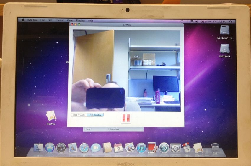
342 23rd USENIX Security Symposium USENIX AssociationFigure 3: iSeeYou running on a white MacBook “Core 2 Duo” capturing video from the internal iSight with the LED (the
black dot to the right of the square camera at the top, center of the display bezel) unilluminated.
a built-in iSight using the appropriate vendor and product Table 2: Overview of possible defenses.
IDs. If the iSight is found, iSeeYou initiates the repro-
gramming process using the modified firmware described Defense Deployable User Root
above. Once the camera has been reprogrammed and Change hardware No Yes Yes
has reenumerated, the start/stop button begins/ends cap- Change firmware Yes No No
turing and displaying video. The LED Enable/LED App Sandbox Yes Some No
Disable control sends USB device requests with the iSightDefender Yes Yes No
new vendor-specific value to enable/disable the indicator
LED while video is being captured. Finally, when the
A “Yes” in the Deployable column indicates that
user quits iSeeYou, the camera is reprogrammed with the the defense could be deployed to existing computers.
legitimate firmware. A “Yes” in the User (resp. Root) column indicates
7 Defenses that the defense would prevent an unprivileged (resp.
root) process from reprogramming the iSight. A
There are several approaches one can envision to defend “Some” indicates that some reprogramming attempts
the iSight against the attacks described in the previous sec- would be prevented but others allowed.
tions. One can change (1) the hardware, (2) the firmware
on the EZ-USB (unfortunately this is not effective, see be-
low), or (3) the software on the host system. See Table 2 If the hardware must remain the same, then if the
for an overview of possible defenses and their efficacy. firmware on the camera could be changed to disallow
The most comprehensive defense would be to change future reprogramming, then the camera would be secure
the hardware used in the iSight. See Section 8 for sev- against our attacks. Unfortunately, the “Firmware Load”
eral secure hardware designs. Of course, changing the USB device request used to reprogram the 8051 core is
hardware is not a deployable solution for existing de- handled entirely by the EZ-USB device itself and cannot
vices. be blocked or handled by the 8051 itself [13, Section 3.8].
7
USENIX Association 23rd USENIX Security Symposium 343Thus no matter how one programs the device’s firmware, and, if so, log the attempt in the system log and block the
it can be reprogrammed by an attacker who can send basic request.
USB messages to the camera. iSightDefender is able to block all user space re-
Apple deploys sandboxing technology called the App programming attempts,8 including those mounted from
Sandbox6 [4] which can prevent applications inside within a virtual machine. The latter requires some care as
the sandbox from accessing the iSight. Specifically, the normal drivers that match against the IOUSBDevice
the com.apple.security.device.camera enti- are unloaded and the virtual machine monitor’s own driver
tlement enables an application to capture still images is loaded in their place.
and video from cameras, including the internal iSight. Using iSightDefender raises the bar for attackers by
The com.apple.security.device.usb entitle- requiring the attacker to have root privileges in order to
ment enables applications to access USB devices. reprogram the iSight. In some sense, this is the strongest
Any App Sandbox–protected application lacking the possible software-based defense. Since malware running
usb entitlement would be prohibited from reprogram- as root would have the ability to replace or modify kernel
ming the iSight and thus prohibited from disabling the code, any defense implemented in the kernel can, theoret-
indicator LED. Although an application with the usb en- ically, be bypassed. Despite this limitation, we believe it
titlement but lacking the camera entitlement would be is a step in the right direction and encourage its use.
prohibited from using the high-level APIs for accessing iSightDefender, and its source code, is freely avail-
the camera, such as the QTKit API [3], it could easily able.9
reprogram the camera to not appear as a USB video class
(UVC) device and instead transfer the frames of video
8 Secure camera designs
using a custom protocol. When designing a secure camera, there are two main
The major drawback to using the App Sandbox to pro- considerations. First, for sensors such as cameras and
tect the camera is that applications need to opt into the microphones, an indicator that the sensor is recording is
protection, something malware is unlikely to do. Worse, essential to prevent surreptitious recording. (Although
the App Sandbox has, at times, been broken allowing laptop microphones do not, in general, have indicators, it
applications to escape from the restrictions [12, 38]. is common for stand alone USB microphones; see [29]
Perhaps the best way to defend against reprogramming for an example.) For the highest level of assurance that
the iSight without changing the hardware is to modify the indicator cannot be bypassed, the indicator should be
the operating system to prevent particular USB device controlled completely by hardware.
requests from being sent to the camera. We have built Second, as with any peripheral connected to the com-
such a defense structured as an OS X kernel extension puter, a vulnerability in the firmware running on the pe-
called iSightDefender. ripheral or the ability to reprogram the firmware enables
When iSight is powered for the first time, it enumer- an attacker to leverage all of the capabilities of the periph-
ates with vendor ID 0x05ac and product ID 0x8300 eral. Section 2 contains numerous examples of this. The
and is programmed with the legitimate firmware via the virtual machine escape in Appendix A is another example
AppleUSBVideoSupport kernel extension as described in where an attacker leverages the USB connection and the
Sections 3.3 and 4.2. When it reenumerates with prod- ability of the EZ-USB to mimic any USB device to the
uct ID 0x8501 the kernel matches and loads the normal host computer. Apple’s most recent FaceTime cameras
drivers as well as iSightDefender. in its 2013 MacBook Air model eschews USB 2.0. In-
I/O Kit kernel drivers are written in a subset of C++ stead, the camera is connected to the host computer over
and each USB device is represented by an object of class PCIe [35]. Vulnerabilities in the camera would potentially
IOUSBDevice which is responsible for communicat- enable an attacker to have DMA access to the host sys-
ing with the hardware by sending messages to objects in tem. This is a significantly stronger capability than USB
lower layers of the USB stack. When iSightDefender is access.
started, it overwrites the C++ virtual method table of its 8.1 Secure indicators
“provider” IOUSBDevice to point to the virtual method
table of a subclass of IOUSBDevice.7 The subclass Laptop cameras are typically constructed by pair-
overrides the four DeviceRequest member functions. ing a CMOS image-sensor-on-a-chip (e.g., the Mi-
The overridden implementations check if the device re- 8 In fact, iSightDefender worked so well that one author spent more
quest is for the “Firmware Load” vendor-specific request than an hour attempting to diagnose (nonexistent) problems with iSeeYou
before noticing the tell-tale lines in the system log indicating that iSight-
6 Formerly codenamed Seatbelt. Defender had been loaded by a computer restart and it was blocking
7 There seems to be no supported mechanism for interposing on USB reprogramming requests.
device requests. The authors appreciate the irony of using virtual table 9 https://github.com/stevecheckoway/
hijacking — a common hacker technique — for defending against attack. iSightDefender
8
344 23rd USENIX Security Symposium USENIX Associationcron MT9V112 found in the iSight or the Toshiba quently be changed by configuring the sensor. This
TCM8230MB(A)) with a separate microcontroller that is analogous to the situation with the iSight where
handles communication with the host computer (e.g., the we changed the meaning of the STANDBY signal.
EZ-USB FX2LP found in the older MacBooks or the An all-in-one design where the image sensor is inte-
Vimicro VC0358 [61] found in more recent MacBook grated with the microcontroller which communicates to
Pros [28]. There are, of course, many possible combi- the host computer is likely to have fewer options for a
nations of image sensors and microcontrollers one could secure design. A dedicated output pin which could drive
use. an indicator LED would suffice. However, hardware de-
Image-sensors-on-a-chip tend to have a number of com- signers are typically loathe to dedicate pins to specific
mon features that can be used to build a secure indicator. functions, instead a variety of functions tend to be multi-
1. Separate power connection for CMOS sensor itself. plexed over a single pin.
For example, VAAPIX on the MT9V112 powers It is likely that, even in this case, there would be a
its pixel array and PVDD on the TCM8230MB(A) separate power connection for the CMOS sensor. As with
powers its photo diode. A GPIO pin on the micro- the two-chip design above, the LED driver circuit and a
controller can be connected to both the LED driver power supply circuit could be driven by a GPIO.
circuit and the CMOS sensor power supply circuit.
8.2 Secure firmware
Whenever images are to be captured, the microcon-
troller sets its GPIO pin appropriately, power is sup- Although using one of the secure indicator designs de-
plied to the sensor and the LED turns on. scribed above will ensure the LED will turn on when
2. #RESET pins. The LED driver circuit can be con- the camera turns on, it does nothing to protect against
nected to the #RESET pin and a GPIO pin on the reprogramming attacks.
microcontroller. The microcontroller would hold the For this, we make four concrete recommendations
image sensor in reset whenever it was not captur- which, taken together, can secure the firmware on the
ing images. Compared to the power connection for camera. These apply more generally to any peripheral or
CMOS sensor, holding the entire sensor-on-a-chip embedded system connected to a host computer.
in reset means that before images could be captured, 1. Store the firmware in nonvolatile storage on the cam-
the sensor would need to be reconfigured. Recon- era module. Most commercial off-the-self (COTS)
figuring typically means sending a few dozen bytes microcontrollers contain some amount of nonvolatile
over an I2 C or SPI bus. This introduces a slight storage, such as flash memory, to hold firmware.10
delay. By programming the firmware at the factory, one
3. Output clocks and synchronization signals. Image avoids the possibility that the legitimate firmware
sensors typically latch outputs on one edge of an will be replaced by an attacker on the host system
output clock signal and image consumers are ex- before being downloaded to the microcontroller.
pected to read the data on the other edge of the Depending on the specific requirements of the
clock. In addition, there are signals used to indicate system, the factory programming could be the com-
which part of the image the latched data represents. plete firmware or a secure loader designed to load
For example, the MT9V112 has FRAME_VALID cryptographically signed firmware from the host (see
and LINE_VALID signals indicating when it’s out- below).
putting a frame or a line within the frame, respec- 2. Use a microcontroller which can block unwanted
tively, whereas the TCM8230MB(A) has VD and HD firmware reprogramming attempts. It is essential that
for vertical and horizontal synchronization. These trusted code running on the microcontroller is able
pins can also be used to control the LED by adding to block reprogramming attempts for illegitimate
some simple hardware that drives the LED if it has firmware.
seen one of these signals change in the past few 3. Firmware updates, if necessary, should be crypto-
milliseconds. graphically signed and the signature verified before
Depending on the specifics of the image sensor applying the update. This requires both nonvolatile
output signal, a retriggerable, monostable multivi- storage for the code to verify the signature and a
brator can be used to drive the LED as long as its microcontroller which can block reprogramming at-
input changes sufficiently often. The multivibrator’s tempts. Since microcontrollers are typically resource
output pulse width needs to be set appropriately such constrained devices, choosing an appropriate signa-
that it is triggered frequently enough to continuously ture scheme which can be implemented within the
drive the LED while images are being recorded. 10 Microcontrollers without nonvolatile storage can be paired with
Some care must be taken when using these output external nonvolatile storage, such as flash or an EEPROM, to the same
signals. The exact meanings of the signals can fre- effect.
9
USENIX Association 23rd USENIX Security Symposium 345constraints is important. Scheme selection is outside tration tools (RATs) on victims’ computers. There are
the scope of this paper but we note that recent micro- several popular RATs, including Blackshades and Dark-
controllers have started to contain specialized crypto Comet, which come with a variety of features such as
instructions which can reduce code size and increase keyloggers, the ability to install additional malware, and
efficiency. For example, Rohde et al. [53] use spe- the ability to record video and sound using the webcam.
cialized AES instructions in some Atmel ATxmega Rats are often installed with the goal of spying on women.
microcontrollers to implement the Merkle signature RATs and the ratters who use them have recently come
scheme. under public scrutiny after a recent Miss Teen USA’s
4. Require root/administrator privileges to send repro- webcam was used by ratter Jared Abrahams to capture
gramming requests. Strictly as a matter of defense her naked images without her knowledge [15]. Abrahams
in depth, software running on the host system should arrest and guilty plea came on the heels of an ars technica
restrict reprogramming attempts. Thus, even if the exposé on ratters [1].
hardware and firmware defenses prove inadequate, A commonly asked question on forums devoted to rat-
this added layer of protection can still defend against ting, such as the Hack Forums “Remote Administrator
some attacks. Tools” forum, is how can one disable the webcam’s LED.
Adding this sort of restriction typically involves a In one representative thread, forum user “Phisher Cat”
device-specific kernel module (our iSightDefender asks
is an example). This may be more difficult for plug
So as all of you know, newer laptops have
and play devices expected to conform to standard
a light when a laptop webcam turns on, and so
protocols and interact with generic drivers such as
this scares the slave.
USB video class (UVC) or USB human interface
Is it theoretically possible for a RAT to dis-
device (HID) class devices.
able this light? [47]
The inability of the EZ-USB to block reprogramming
attempts indicates that this widely-used microcontroller disturbingly referring to his victim as “the slave,” as is
is inappropriate for use in any system where security is a common in this subcommunity. The first response by
consideration. “Jabaar” notes that “[p]eople have been trying to figure
this out for a very long time. The light won’t be able to
Secure physical user interface Orthogonal to secure be disabled as it is built into the hardware.” Others agree:
indicators and secure software is a secure physical user “Capital Steez” writes that there is “no way to disable it,”
interface. Most webcams in laptops are controlled by and “FBITM ” concurs “there [i]s no way to do” it. Still
software: Software tells the camera when to power up, others suggest using social engineering in an attempt to
when to capture video, and when to power down. A convince the victim that the LED is normal, for example,
simple solution to the problem is to provide a physical “Orochimaru” writes, “You can’t physically turn it off but
switch similar to the switches found on laptop network you can use social engineering to fool them. Maybe send
adapters which controls power to the camera. A second an error or warning msgbox that says ‘Camera is now
simple solution is to provide a lens cover which the user updating, please do not disturb’ or something.” There are
must physically move aside to use the camera. This would many such threads on Hack Forums alone, all expressing
be similar in spirit to the original external iSight and similar sentiments: disabling LEDs is a capability the
similar in form to the amusingly named iPatch [58]. ratters really want to have but do not think is possible.
Unfortunately, the implications of surreptitiously cap-
9 Discussion
turing video do not end with privacy violations like law
Although some webcams, such as the Logitech QuickCam enforcement, school officials, and ratters spying on peo-
Pro 9000, come with an explicit “LED control” that can ple. As part of the general trend of growing frustration
disable the LED [64], such controls are not the norm and, with passwords as an authentication mechanism, some
in fact, are a very bad idea from both a security and a companies are moving to biometric identification; in
privacy stand point. Giving the user the ability to disable particular, using facial recognition on video taken with
a privacy feature is tantamount to giving malware the webcams. For example, BioID is software-as-a-service
same capability. which provides biometric identification to online service
This work concerns the technical challenge of hard- providers using a webcam [8]. Luxand’s FaceSDK is
ware exploitation; however, we would be remiss if we a cross-platform software development kit that uses the
did not discuss the (frequently unpleasant) real-world webcam to identify the user [34].
consequences of vulnerabilities in privacy technology. In principle, this sort of facial recognition is trivially
A particularly unsavory element of the hacker culture, defeated by providing the expected picture or video to
“ratters,” install malware bundled with remote adminis- the software performing the authentication. Malware that
10
346 23rd USENIX Security Symposium USENIX Associationcan capture video of the victim can replay that video to indicator LED hardware interlocks to be bypassed, mal-
authenticate to the given service. This is not a new attack. ware is able to covertly capture video, either for spying
The Android Face Unlock system was defeated shortly purposes or as part of a broader scheme to break facial
after being released by holding a picture of the face in recognition authentication. Although the iSightDefender
front of the camera [9]. Duc and Minh [16] describes defense described in Section 7 raises the barrier for mal-
weaknesses of several facial recognition authentication ware, including RATs, to take control of the camera with-
systems in the presence of pictures. By disabling the out being detected by requiring root privileges, the correct
indicator LED before capturing video, the victims have no way to prevent disabling the LED is a hardware solution.
way of knowing that their accounts may be compromised. In this paper, we have examined only a single genera-
Although the ability to disable the LED can lead to tion of webcams produced by a single manufacturer. In
serious privacy and security problems, there are at least future work, we plan to expand the scope of our inves-
two legitimate use cases. The first is that some people tigation to include newer Apple webcams (such as their
really do not want the LED on while they are recording. most recent high-definition FaceTime cameras) as well as
We do not find this to be a compelling use as the benefit webcams installed in other popular laptop brands.
does not seem to outweigh the potential cost; however, The virtual machine escape described in Appendix A
others may value this more than we do. demonstrates the danger that reprogrammable peripheral
The second use case is significantly more compelling: devices such as keyboards and mice pose. We plan to
laptop recovery. For example, the OS X version of undertake a much broader examination of these devices
Adeona software captures pictures using the laptop’s in- in an attempt to understand the security implications of
ternal iSight to aid in recovery of a laptop that has been connecting one device to a computer which can, under at-
stolen by taking a picture of the thief [51, 52]. The LAN- tacker control, pretend to be a wide range of devices. One
rev software used in the Lower Merion School District particularly promising direction is to study how drivers
incident discussed in the introduction had a similar “Theft react to malformed or malicious responses from devices.
Track” feature which is how the school officials were able In the worst case, a user space program could reprogram
to obtain pictures of students. For this use, one does not a peripheral device which in turn exploits a poorly written
want the thief to know he is being observed. driver to inject code into the kernel.
10 Responsible disclosure Acknowledgments
The authors followed responsible disclosure practices by We thank the anonymous reviewers for their detailed com-
disclosing the LED disabling vulnerability to Apple prod- ments and helpful suggestions. We also thank Brian Kan-
uct security team on July 16, 2013 and the virtual machine tor, Nick Landi, Eric Rescorla, Stefan Savage, Hovav
escape on August 1, 2013. The disclosures included the Shacham, and Cynthia Taylor for many helpful discus-
source code for iSeeYou and the virtual machine escape sions throughout this work and Kevin Mantey for letting
as well as directions for mounting both attacks. Apple us borrow test equipment and providing technical assis-
employees followed up several times but did not inform tance.
us of any possible mitigation plans. The iSightDefender
code was also provided to Apple and is now publicly
References
available.11 [1] Nate Anderson. Meet the men who spy on women
through their webcams. ars technica, March 2013.
11 Conclusions and future work Online: http://arstechnica.com/tech-
Engineering details of privacy technologies can have real- policy/2013/03/rat-breeders-meet-
world consequences. As discussed in Sections 1 and 9, the-men-who-spy-on-women-through-
a computer user today potentially faces a variety of ad- their-webcams/.
versaries — from law enforcement and school officials to [2] I/O Kit Fundamentals: Driver and Device Match-
criminals — who want to capture images or video clandes- ing. Apple Inc., May 2007. Online: https:
tinely. Currently, the only technological barrier standing //developer.apple.com/library/
in their way is the camera-on indicator LED. We have mac/#documentation/devicedrivers/
shown that, at least in some cases, the barrier can be conceptual/IOKitFundamentals/
overcome. Matching/Matching.html.
In particular, we have shown that being able to repro-
gram the iSight from user space is a powerful capability. [3] QTKit Framework Reference. Apple
Coupled with the hardware design flaw that allows the Inc., February 2009. Online: http://
developer.apple.com/library/
11 See supra note 9. mac/#documentation/QuickTime/
11
USENIX Association 23rd USENIX Security Symposium 347Reference/QTCocoaObjCKit/_index. 2011. Online: http://www.coresecurity.
html. com/content/apple-osx-sandbox-
bypass.
[4] App Sandbox Design Guide. Apple
Inc., March 2013. Online: http:// [13] EZ-USB R
Technical Reference Manual. Cy-
developer.apple.com/library/ press Semiconductor Corporation, 2011. On-
mac/#documentation/Security/ line: http://www.cypress.com/?docID=
Conceptual/AppSandboxDesignGuide/ 27095&dlm=1.
AboutAppSandbox/AboutAppSandbox.
[14] Cypress Semiconductor Corporation. CY3684 EZ-
html.
USB FX2LP Development Kit. 2013. Online:
[5] Ballard Spahr. Lower Merion School District foren- http://www.cypress.com/?rID=14321.
sics analysis: Initial LANrev system findings, May
[15] Alex Dobuzinskis. California man agrees
2010. Online: http://www.scribd.com/
to plead guilty to extortion of Miss Teen
doc/30891576/LMSD-Initial-LANrev-
USA. Reuters, October 2013. Online: http:
System-findings. Redacted.
//www.reuters.com/article/2013/
[6] Ballard Spahr. Report of independent investigation: 10/31/us-usa-missteen-extortion-
Regarding remote monitoring of student laptop idUSBRE99U1G520131031.
computers by the Lower Merion School District,
[16] Nguyen Minh Duc and Bui Quang Minh. Your
May 2010. Online: http://www.social-
face is NOT your password: Face authentica-
engineer.org/resources/100503_
tion bypassing Lenovo – Asus – Toshiba. Pre-
ballard_spahr_report.pdf.
sented at BlackHat Briefings, July 2009. On-
[7] Étienne Bersac. iSight Firmware Tools. Octo- line: https://www.blackhat.com/html/
ber 2009. Online: https://launchpad.net/ bh-usa-09/bh-us-09-main.html.
isight-firmware-tools.
[17] Loïc Duflot and Yves-Alexis Perez. Can
[8] BioID, Inc. The easy, secure way to log you still trust your network card? Presented
in and manage online identities and accounts. at CanSecWest 2010, March 2010. Online:
2013. Online: http://mybioid.com/index. http://www.ssi.gouv.fr/IMG/pdf/
php?id=67. Last accessed: 2013-08-06. csw-trustnetworkcard.pdf.
[9] Matt Brian. Android 4.0 Face Unlock feature [18] Loïc Duflot, Yves-Alexis Perez, and Benjamin
defeated using a photo. The Next Web, Novem- Morin. What if you can’t trust your network
ber 2011. Online: http://thenextweb. card? In Robin Sommer, Davide Balzarotti,
com/google/2011/11/11/android-4- and Gregor Maier, editors, Proceedings of RAID
0-face-unlock-feature-defeated- 2011, pages 378–397. Springer, September 2011.
using-a-photo-video/. Online: http://www.ssi.gouv.fr/IMG/
pdf/paper.pdf.
[10] camJAMR.com. camJAMR.com webcam
covers. 2012. Online: http://store. [19] Monta Elkins. Hacking with hardware: Introduc-
camjamr.com/shop-now/camjamr- ing the universal RF USB keyboard emulation de-
webcam-covers.html. Last accessed: vice: URFUKED. Presented at DefCon 18, August
2013-08-07. 2010. Online: http://www.youtube.com/
watch?v=EayD3V77dI4.
[11] Stephen Checkoway, Damon McCoy, Danny An-
derson, Brian Kantor, Hovav Shacham, Stefan [20] William Enck, Peter Gilbert, Byung-Gon Chun,
Savage, Karl Koscher, Alexei Czeskis, Franziska Landon P. Cox, Jaeyeon Jung, Patrick Mc-
Roesner, and Tadayoshi Kohno. Comprehensive Daniel, and Anmol N. Sheth. TaintDroid: An
experimental analyses of automotive attack sur- information-flow tracking system for realtime
faces. In David Wagner, editor, Proceedings of privacy monitoring on smartphones. In Remzi
USENIX Security 2011. USENIX, August 2011. Arpaci-Dusseau and Brad Chen, editors, Proceed-
Online: http://www.autosec.org/pubs/ ings of OSDI 2010. USENIX, October 2010. Online:
cars-usenixsec2011.pdf. http://static.usenix.org/events/
osdi10/tech/full_papers/Enck.pdf.
[12] CoreLabs, Core Security Technologies. Apple OS
X Sandbox predefined profiles bypass. November [21] Dan Farmer. IPMI: Freight train to hell, January
12
348 23rd USENIX Security Symposium USENIX AssociationYou can also read