LATVIAN JOURNAL OF PHYSICS AND TECHNICAL SCIENCES 2020, N 1 - Hat Lab
←
→
Page content transcription
If your browser does not render page correctly, please read the page content below
LATVIAN JOURNAL OF PHYSICS
                                                   AND TECHNICAL SCIENCES
                                                                    2020, N 1

                                                          DOI: 10.2478/lpts-2020-0001

         ANTARR – ETNA LOW FREQUENCY ANTENNA ARRAY

             G. Tuccari, M. Wunderlich, S. Dornbusch, G. G. Tuccari

  INAF – Institute of Radioastronomy, 101 Gobetti Str., 40126 Bologna, ITALY
                   Max Planck Institute for Radio Astronomy,
                  69 Auf dem Hugel, 53121Bonn, GERMANY
             HAT-Lab Ltd., 97 Milano Str., 95127 Catania, ITALY

              A project called AntArr as a new application of the DBBC3 (Digital Base
      Band Converter, 3rd generation) is under development. A group of antennas
      operating at low frequency, in the range from 10 MHz up to 1500 MHz, are
      phased up for VLBI, pulsar and more recently for FRB observations. Part of
      the scientific programme is also dedicated to SETI activities in piggy-back
      mode. Dedicated elements can even be added to reach still lower frequencies
      to observe the range down to kHz frequencies. The DBBC3 manages the
      array operations in a selected portion of the band and the main characteristic
      is to synthesize a beam with an innovative approach. The final product of the
      array is a single station standard VLBI data stream for correlation with other
      antennas, or a synthesized beam for single dish observations. A number of
      antennas and array prototypes are under test at a location on the Etna volcano
      slope, with the aim to form a complete radio telescope of up to 1024 elements
      in 2020 and beyond. This project completes the lower part of the frequency
      spectrum covered in VLBI by the BRAND EVN project. The project AntArr is
      hosted and financed by HAT-Lab Ltd., which is the manufacturer of the DBBC
      family backends.
              Keywords: Antenna array, BRAND EVN, DBBC backend, VLBI

                                1. INTRODUCTION

       A project called AntArr as a novel application of the DBBC3 [1], [2] (Digital
Base Band Converter, 3rd generation) is presented in the study. It is development
under construction on the Etna volcano slopes at low altitude (about 600 meters).
A group of antennas operating at low frequencies, in the range from 10 MHz to
1500 MHz, are phased up for VLBI or pulsar observations. Moreover, dedicated
elements can be added to reach still lower frequencies to observe the range down
to kHz frequencies. The DBBC3 manages the array operations in a selected portion
of the band and the main characteristic is to synthesize a beam with an innovative
approach. The final product of the array is a single station standard VLBI data stream
                                            6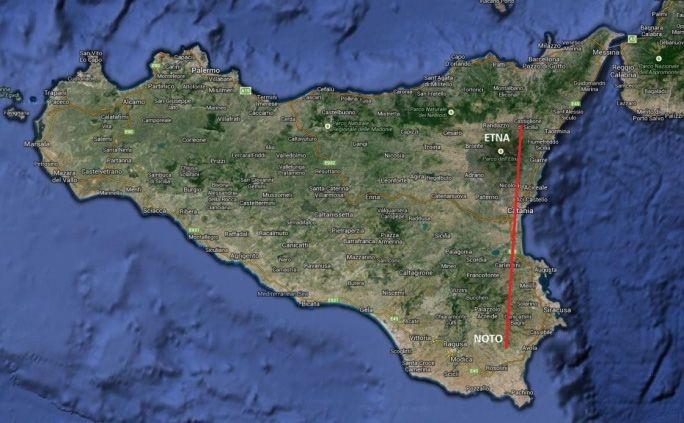
for correlation with other antennas, or a synthesized beam for pulsar observations. A
number of different antennas, receivers and array prototypes have been implemented
since the 2014 and have been under test at two locations for measurements and
evaluation. In the end, the most suitable architecture has been selected in terms of
performance, dimensions and cost. Such selected configuration is then used to build
the array in a sufficient number of elements to allow for the complete functionality.
       The selection of the antenna type considered the possibility to have add-on
elements to reduce a lower range of frequency the array can receive up to a lower
limit of few KHz. Such additional elements are under development and a number of
prototypes are under evaluation.

                            2. ARRAY ARCHITECTURE

       The general architecture of the AntArr instrument is schematically indicated
in Figs. 1, 2 and 3. Each green circular element represents a single antenna. Most
of such antennas are organized in arms to form a matrix whose rows are subject to
the progressive formation of the array signal that is finally forwarded to one of the
inputs of the DBBC3. A maximum number of 32 inputs are available for a maximum
number of 32 elements in a single arm, bringing the maximum number of elements
of the array to 1024. The arms are disposed in E-W oriented rows having any row in
both ends allows operating as an independent array of ‘level one’. Groups of rows
are organised in a further ‘level two’ array, and finally the entire set of groups is
organised as ‘level three’ of array, which is the final arrangement. This distinction
is motivated by the fact that separated elements in the array matrix can be selected,
making use of cross correlation of the combined received signals to simplify the
array calibration.

                        Fig. 1. Antenna array managed by the DBBC3.

             Fig. 2. Schematic structure of antenna array with its main components.

                                               7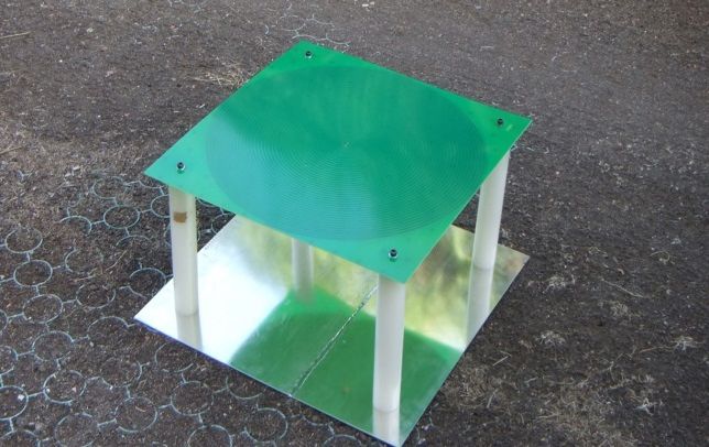
Fig. 3. Array signal distribution.

General features of the array and beam synthesis

      The main general features of the instrument are as follows:
      • Antenna prototype frequency range: 15 MHz–1500 MHz;
      • Max. number of antennas in a single arm: 32;
      • Max. number of arms with a single DBBC3: 32;
      • Max. observation bandwidth of each arm: 1500 MHz;
      • Analogue delay compensation digitally controlled at every antenna;
      • Analogue summation for each arm at every antenna;
      • Digital correlation between elements of the array;
      • Digital correlation between elements of the array and the synthesized
         beam.

                        3. ANTENNAS AND RECEIVER

      The signals of the developed antenna array are processed by the VLBI backend
DBBC3L [3]. As mentioned above, a set of antennas is organized in arms, in groups
managed by a single ADB3L-CORE3H in order to create one or more synthesized
beams. The signal from each antenna has the model delay applied to compensate
the path length difference of the incoming radiation relative to its direct neighbour
antenna. The delayed signal is summed to this next neighbour.
      The resulting signal has again the model delay applied relative to its next
neighbour and the combined signal is added to it and so on, up to the DBBC3 processor.
Any single beam is also available to be correlated with either the synthesized beam
or with any other element in the array to precisely determine the delay residual with
respect to the model of single elements as a function of the time. The signal of the
source is then tracked with a mix of theoretical geometric model and the residuals
determined with the array itself.
                                             8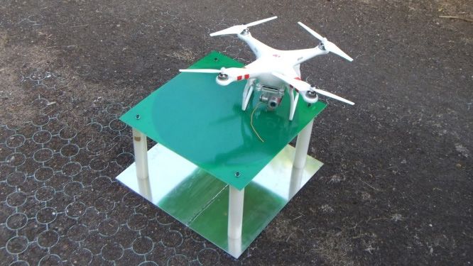
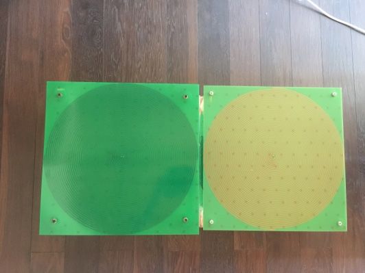
Figures 4a and 4b show the prototype of the selected antenna in double and
single circular polarization, respectively, while its 3D beam is reported in Fig. 5.
Fig. 4a. Antenna in double polarization. Fig. 4b. Antenna in single polarization.
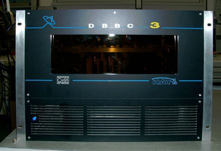
Fig. 5. Single antenna beam. Fig. 6. The receiver, three amplification stages.
The receiver (Fig. 6) is a low-noise amplifier of three amplification stages
with a high dynamic range. The receiver is composed of two boards, one for the
amplification stages and the other for the delay control. The latter is included in the
distribution cables and is controlled by the DBBC3. The entire single receiver with
the antenna enclosure behaves at a system temperature in the order of 300 K at 500
MHz.
Particular care is to be applied for the implicit RFI crowded environment the
array is asked to work in. Figures 7a and 7b show the RFI condition in the site
where the array is under construction, the monitors for pointing and total power
detected. Even in a severe environment portions of band can be selected where
observations are still possible. In order to take into account this aspect, three wide
range antennas looking at the terrestrial emissions have been dedicated to track and
identify the direction of the worst case emissions: such information is considered in
the beam forming so to make minimum contribution of side lobs of the synthesized
beam. Dedicated software entirely developed by HAT-Lab research merges pointing
beam forming and RFI minimisation. Then a two-way tracking is implemented, one
9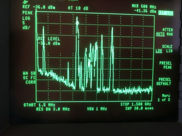
pointing to the extra-terrestrial source to be observed, and the other to the counter-
pointing on the terrestrial emissions. This method is still under study and until now
could provide attenuation of the RFI in the total power regime of up to 25–30 dB,
resulting in a promising method when optimised.
Fig. 7a. RFI environment in the Etna site Fig. 7b. Monitors: array pointing, total. power.
4. STATIONS AND ARRAY CHARACTERISATION
At the early stages of the project development, two stations have been
equipped with a few prototypes for testing the network capability: one in the vicinity
of the Noto radio telescope, the other on the northern slope of the Etna volcano at
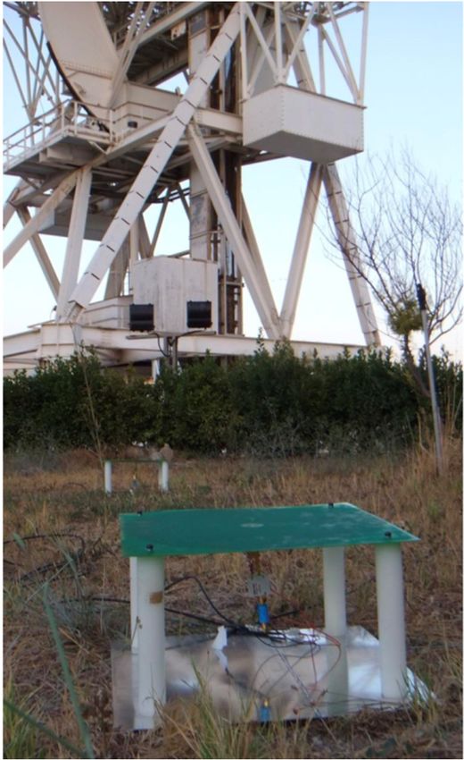
low altitude, the site where now the array will be fully installed. Figures 8a and 8b
show a view of the relative position of the sites in Italy, in the Sicily Island, and one
of the prototypes close to the Noto radio telescope.
Fig. 8a. Baseline Noto – Etna site. Fig. 8b. Antenna prototype at the
Noto radio telescope.
10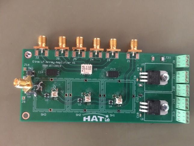
A drone equipped with a multi-frequency transmitter is used to test and
characterise a single antenna and groups of antennas in the far-field regime. The
vehicle can be placed in the sky at fixed positions controlled by an on-board GPS
and an altimeter in order to determine the 3D complex beam of a single antenna and
the part of the array under analysis. This method allows performing holographic
measurements of the physical position of the single array element to make a map for
the beam synthesis. Figure 9 illustrates the calibration method.

      Fig. 11. Drone with a transmitter for 327, 654, 981 MHz is used for the array calibration.

                                   5. CONCLUSIONS

       The new antenna array named AntArr operating with a synthesis beam is
under construction on the Etna volcano and mainly dedicated to VLBI observations.
The array is an innovative demonstration prototype expected to operate in a low
frequency range, starting at around 10 MHz and extending up to 1.5 GHz. Such
frequency is a lower boundary of the BRAND EVN receiver, which is a project
under development, financed under Radionet4 Horizon2020 and expected to cover
the range between 1.5–15.5 GHz. Thus, the AntArr project is virtually extending a
lower portion of the frequency spectrum for VLBI observations. The project is fully
financed by HAT-Lab Ltd., the Italian company producing the DBBC VLBI backend
family.

                                       REFERENCES

1. Tuccari, G. (2011). DBBC3. In Proceedings of the 20th EVGA Meeting and 12th Analysis
   Workshop (pp. 19–21), Bonn, Germany.
2. Tuccari, G., Alef, W., Buttaccio, S., Tornatore, V., & Wunderlich, M. (2014). DBBC3:
   AntArr Project. In Proceedings of Science, 12th European VLBI Network Symposium
   and User Meeting, 7–10 October 2014, Cagliari, Italy.
3. Tuccari, G., Alef, W., Bertarini, A., Buttaccio, S., Casey, S., Comoretto, G., … &
   Wunderlich, M. (2014). DBBC3: VLBI at 32 Gbits per second. In Proceedings of
   Science, 12th European VLBI Network Symposium and User Meeting, 7–10 October
   2014, Cagliari, Italy.

                                                11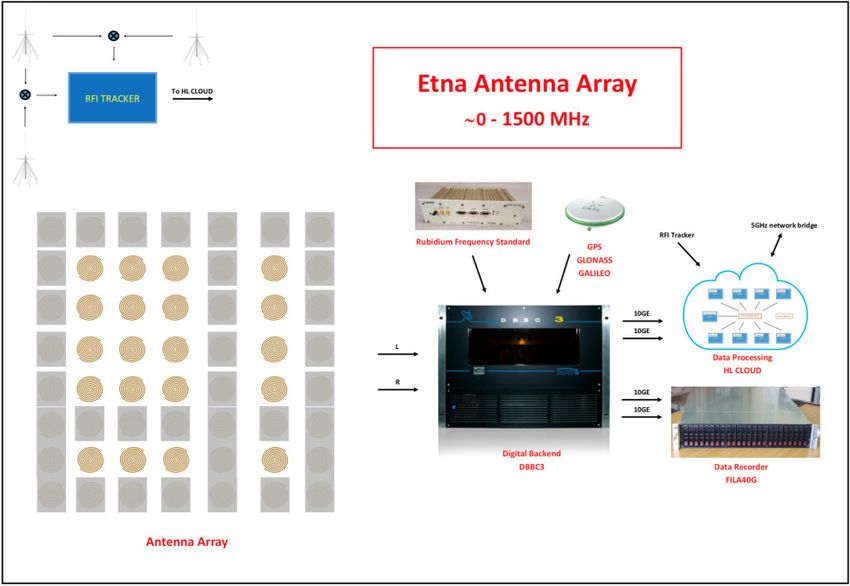
ANTARR – ETNAS ZEMFREKVENCES
                          ANTENU MASĪVS

               G. Tukari, M. Vunderlihs, S. Dornbušs, G. G. Tukari

  INAF – Radioastronomijas institūts, Gobetti iela 101, 40126, Boloņa, Itālija
Maks Planka Radioastronomijas institūts, Auf dem Hugel 69, 53121, Bonna, Vācija
            SIA “HAT-Lab”, Milano iela 97, 95127, Katānija, Itālija

                                Kopsavilkums

       Projekts ar nosaukumu “AntArr” tiek izstrādāts kā jauna lietojumprogramma
DBBC3 (3. paaudzes ciparu bāzes joslas pārveidotājs). Antenu grupa, kas darbojas
zemo frekvenču diapazonā no 10 MHz līdz 1500 MHz, tiek pakāpeniski salāgota
it īpaši lielas bāzes interferometrijas (VLBI), pulsāriem un nesen ātro radio
uzliesmojumu (FRB) novērojumiem. Daļa no zinātniskās programmas veltīta arī
SETI aktivitātēm. Antenas masīvam var pat pievienot klāt specializētus elementus,
lai sasniegtu vēl zemākas frekvences un novērotu diapazonu līdz kHz frekvencēm.
DBBC3 pārvalda antenu masīva operācijas izvēlētā joslas daļā, un galvenais
uzdevums ir sintezēt staru ar inovatīvu pieeju. Antenu masīva gala produkts ir vienas
stacijas datu straume VLBI standarta korelācijai ar citām antenām vai sintezēts stars
novērojumiem vienas antenas režīmā. Vairāki antenas un bloku prototipi ir realizēti,
un tie tiek pārbaudīti Etnas vulkāna nogāzes vietā ar mērķi 2020. gadā sāk veidot
strādājošo radioteleskopu, kas sastāvēs no līdz pat 1024 elementiem. Šis projekts
nosedz frekvenču spektra apakšējo daļu VLBI vajadzībām un ar to papildina
BRAND EVN projektu. Projektu AntArr vada un finansē SIA “HAT-Lab”, kas ir
DBBC saimes aparatūras ražotājs.
       Atslēgas vārdi: VLBI, DBBC ciparotājs, antenu masīvs, BRAND EVN

                                         12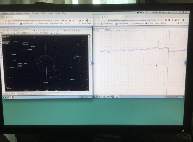
You can also read