Energy saving in street lighting system - Journal of Physics: Conference Series
←
→
Page content transcription
If your browser does not render page correctly, please read the page content below
Journal of Physics: Conference Series

PAPER • OPEN ACCESS

Energy saving in street lighting system
To cite this article: E.Annie Elisabeth Jebaseeli et al 2021 J. Phys.: Conf. Ser. 1770 012039

View the article online for updates and enhancements.

                                This content was downloaded from IP address 46.4.80.155 on 15/07/2021 at 16:14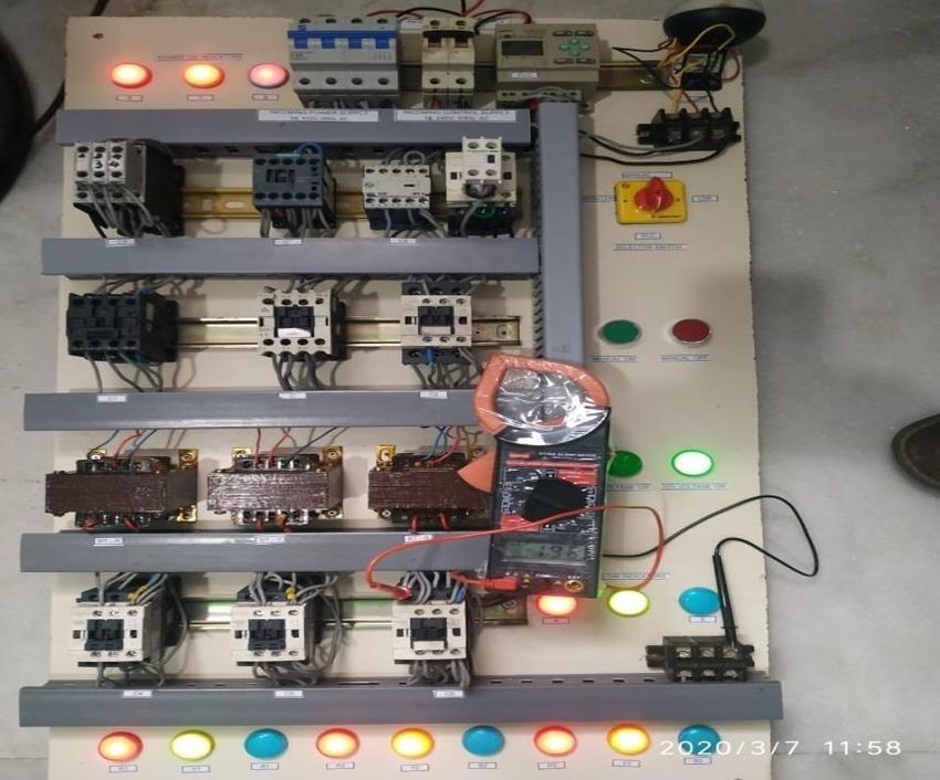
International Conference on Mathematical Sciences (ICMS 2020)                                                   IOP Publishing
Journal of Physics: Conference Series           1770 (2021) 012039                        doi:10.1088/1742-6596/1770/1/012039

                            Energy saving in street lighting system

                     1
                      E. Annie Elisabeth Jebaseeli 2D.susitra 3 Sundaram
                      1,2
                        Associate professors, 3student
                      Sathyabama Institute of science and Technology, Chennai 600119

                      anniejebaseeli@gmail.com

                         Abstract. A street lighting system should be very efficiently designed to provide good
                         visibility, safety and comfort to the users. It must be energy efficient with reduced cost.
                         Generally Street lights are not operated robotically. During summer, the lights are on even
                         during the day resulting in wastage of electricity. In the existing street lighting system,
                         power consumption is more since the lamps glow with full illumination even in the
                         nonappearance of vehicles or pedestrians. To overcome this, an attempt has been made to
                         propose a system which is totally automatic. Thus an efficient and comprehensive scheme
                         for energy saving in illumination is proposed in this paper. The energy saving is
                         implemented using three main methods namely Dawn Dusk Method, Reduced voltage
                         method and one phase cut off randomly and other two phases with reduced voltage
                         method. This idea can exploit the capabilities of energy saving on the street light in well
                         planned township in a systematic manner.

1. Introduction
Recently, the world is moving towards automation due to technological development. For a
developing country energy conservation is the main necessitate. But energy is wasted through various
means. Hence a new system is proposed which is very economical and requires less time to change
the existing system[1,2].
   Developing countries like India face difficulties with lack of power resources due to increase in
population. The survival of the next generation is affected due to over dependency on fossil fuel.
Hence energy consumption must be minimized by adopting various energy proficient techniques
.[3,4].
   The existing street lights consume a huge amount of power since they are in operation in the entire
night even in the absence of vehicles or pedestrians. So this became a most inefficient method. The
main intention of this system is to save energy and man power. Energy Conservation means using
energy more efficiently or with reduced wastage of energy. Industries are the biggest consumers of
energy. In most industries the energy cost forms the large portion of manufacturing cost. So saving
the electrical energy and reducing the wastage of energy is highly essential. Here the LDR sensor is
used to turn ON-OFF the street light based on the ambient intensity level. This avoids unnecessary
power waste during sufficient day light.[5,6]
    In the existing street lighting system, three phase power supply is fed through load power
contactors to the street lighting loads. These power contactors are controlled by the Light dependent
Resistor (LDR). The LDR is installed at a height above the lighting system. Based on the light
intensity on the LDR, it will response and give signals to the power contactors for ‘ON’ and ‘OFF’
the street lighting system. In this system the ‘ON’ and ‘OFF’ exact time of the street lighting system
can’t be fixed because the LDR wholly depend on the natural light, i.e. the climatic condition of the
place on a particular day. In this system there is no reduction of supply voltage, so full rated voltage
is applied to energise the system [7,8].

              Content from this work may be used under the terms of the Creative Commons Attribution 3.0 licence. Any further distribution
              of this work must maintain attribution to the author(s) and the title of the work, journal citation and DOI.
Published under licence by IOP Publishing Ltd                          1
International Conference on Mathematical Sciences (ICMS 2020)                                IOP Publishing
Journal of Physics: Conference Series           1770 (2021) 012039     doi:10.1088/1742-6596/1770/1/012039

2. Proposed street lighting system

               Bucking Transformer
                                                                        3 Phase AC supply
                (Primary winding)

           Voltage tapping Contactor
                                                                        Main Contactor (C)
              (C1-95% & C2-90%)

                                                                       Bucking Transformer
                        LDR                                            (Secondary winding)

                        PLC                                          Load Contactor (C4,C5,C6)

                                                                         Street Light Load

                                    Fig 1. Proposed lighting system

In the proposed street lighting system as shown in Fig 1, power supplies are fed through Main power
contactors, Bucking Transformers and load power contactors to the street lighting loads. The load
power contactors are controlled by the Light dependent Resistor (LDR) and Programmed logic
controller (PLC). The LDR is installed above the lighting system. Based on the light intensity on the
LDR, it will response and give signals to the power contactors for ‘ON’ and ‘OFF’ the street lighting
system. The PLC is installed at the panel itself. Based on the preset timing, it will response and give
signals to the load power contactors for ‘ON’ and ‘OFF’ the street lighting system. Also the PLC
controls the voltage tapping contactors of the bucking transformer. From this control, the primary
winding turns are varied and the secondary voltage of the bucking transformer is also varied,
ultimately the voltage at the lighting system can be controlled [9,10].

                              Fig 2. Proposed power circuit diagram – 1

                                                    2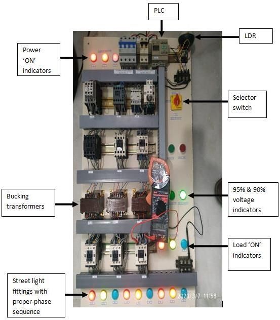
International Conference on Mathematical Sciences (ICMS 2020)                              IOP Publishing
Journal of Physics: Conference Series           1770 (2021) 012039   doi:10.1088/1742-6596/1770/1/012039

   Fig 2. shows the power circuit diagram with three phases, 415V, and 50Hz main power
 connected to the lighting load through the main power contactor, bucking transformer and load
 power contactors. Also it indicates that the lighting loads are connected in proper phase sequence.

                                      Fig 3. Bucking transformer

 Fig 3. shows the bucking transformer connected in subtractive polarity. The primary winding has
 three terminals. One terminal is common Neutral and connected to the load and another two
 terminals are provided with the tapings of the 95% & 90% output voltage with respect to the input
 voltage. It works on the principle of the transformer ratio i.e. V1/V2=N1/N2=K. Also it shows the
 full load current will flow through the secondary winding only but not in primary winding. The
 primary winding can be designed with lower rating and the secondary winding can be designed with
 the rated load. So the size of the transformer will be reduced.
     Fig.4. shows the control circuit diagram with single phase 230V, 50Hz AC supply connected to
 the double pole MCB. From that MCB output, LDR, PLC and other components shown in the
 figure are connected. The LDR will response based on light intensity. The LDR output is connected
 to the single pole 4 way selector switch. In that selector switch there are four output terminals. One
 terminal operates in the manual mode, second one in the LDR mode, third one in the PLC mode and
 final fourth one in the PLC with LDR mode. In the PLC output there are four output terminals of
 Q0, Q1, Q2 and Q3. The Q3 terminal is responsible for the voltage variation from 95% to 90% and
 the Q0, Q1 & Q2 terminals are responsible for the any one phase cut off with respect from the
 preset timing in PLC.

                                                    3
International Conference on Mathematical Sciences (ICMS 2020) IOP Publishing
Journal of Physics: Conference Series 1770 (2021) 012039 doi:10.1088/1742-6596/1770/1/012039
Fig 4. Proposed control circuit diagram
3. Methods and modes of operation
3.1 Methodology
Here the LDR sensor is used to ON-OFF the street light based on the ambient intensity level. This
avoids unnecessary power wastage when sufficient sun light is available. The three main methods
involved in energy saving are Dawn Dusk Method, Reduced voltage method (without interruption),
one phase cut off randomly and other two phases with reduced voltage method.
3,2 Modes of operation
Dawn dusk method
Reduced voltage method
Two phase operation instead of three phase operation
During day time (dawn) the lights are switched off by using timer in PLC so the system shall be in
de-energized condition. When dusk arrives, the lamps are automatically “ON” using PLC programs.
The system shall be energized and it will give signal to contactors to close. The street light circuit
will be closed and the supply to the streetlights will be getting 95% voltage through the bucking
transformer. The bucking transformer is in subtractive polarity. So 5 % of supply Voltage will be
4International Conference on Mathematical Sciences (ICMS 2020) IOP Publishing
Journal of Physics: Conference Series 1770 (2021) 012039 doi:10.1088/1742-6596/1770/1/012039
saved from 6.00 PM to 10.00 PM. Energy saved is nearly 4 hours for all the three phases.
After 10.00 PM the supply to the street lights will be getting 90% of supply Voltage through the
bucking transformer. So 10 % of supply will be saved from 10.00 PM to 12.00 AM. Energy saved
nearly will be 2 hours in all the three phases. After 12.00 AM to 6.00 AM any one of the phase will
be cutoff randomly. The sequence of operation will be controlled by PLC system. Energy saved
nearly will be for 6 hours by using two phases instead of 3 phases.
When DAWN arrives, the PLC make the contactors to open. The system shall be in de- energized
condition. The total assembly will be placed as an energy saving panel and it shall be wired for 95%
& 90% tappings. By using bucking transformer even though the supply voltage changes from 95%
to 90% ,the lamp illumination will not get disturbed.
4. Calculation concepts - Model Calculation
Assume Resistance of the lamp is 100 ohms. Applied Voltage is 230V.
Power = (V*V) / R Watts
= (230*230) / 100
= 529 Watts
For 5% reduced voltage
Power = (V*V) / R Watts
= (218.5*218.5) / 100
= 477 Watts
Saving in power= 10%
For 10% reduced voltage
Power = (V*V) / R Watts
= (207*207) / 100
= 429 Watts
Saving in power = 19%
For one phase
switched ‘OFF’
Saving in power = 100%
For calculation purpose, take three100W lamps glowing from 06.00 PM to 06.00 AM.
Apply the full rated voltage for the whole time and it consumes,
Energy = 12 * 100 * 3 WH
= 3600 WH (or) 3.6 Units.
Apply the 95% of rated voltage for 06.00 PM to 10.00 PM and it consumes,
Energy = 4 * 90 * 3 WH (Saving 10% of Power)
= 1080 WH (or) 1.08 Units.
5International Conference on Mathematical Sciences (ICMS 2020) IOP Publishing
Journal of Physics: Conference Series 1770 (2021) 012039 doi:10.1088/1742-6596/1770/1/012039
Apply the 90% of rated voltage for 10.00 PM to 12.00 AM and it consumes,
Energy = 2 * 81 * 3 WH (Saving 19% of Power)
= 486 WH (or) 0.486 Units.
Apply the 90% of rated voltage for 12.00 AM to 06.00 AM and it consumes,
Energy = 6 * 81 * 2 WH (Saving 19% of Power with one Phase switched ‘OFF’)
= 972 WH (or) 0.972 Units.
So, total energy consumed with this energy saving system per day
Energy = (1.08 + 0.486 + 0.972) WH
= 2538 WH (or) 2.538 Units.
So, Percentage of Energy saving per day = ((3600-2538) / 3600) * 100
= 29.5%
5. HARDWARE IMPLEMENTATION
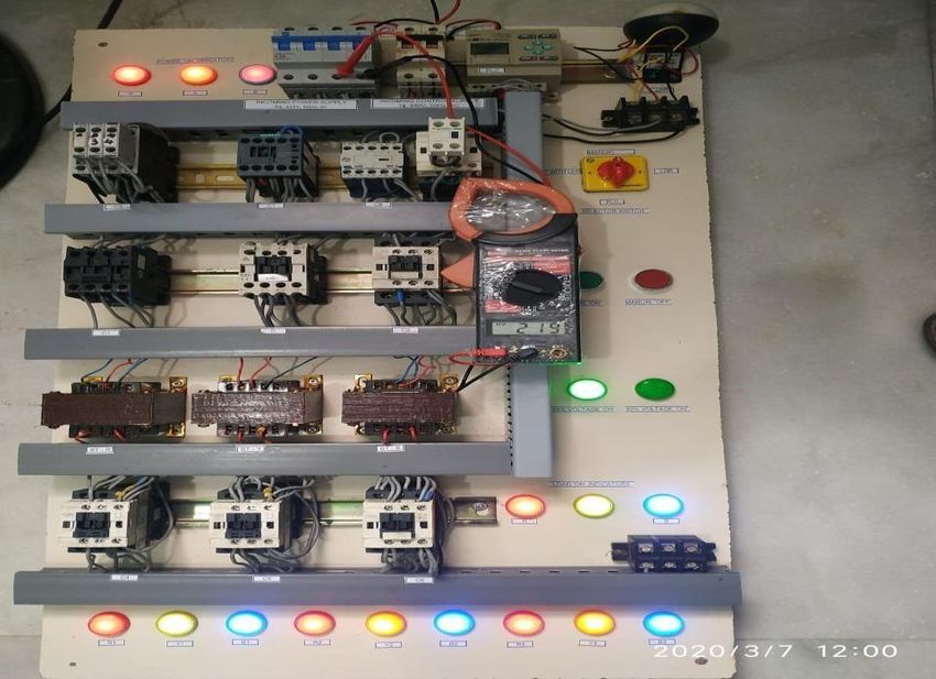
Fig 5. shows 90% of supply Voltage measured at the load terminals i.e. 196V measured. In this
mode Blue Phase switched ‘OFF’ and 90% of supply voltage applied to the load from 12.00 AM
to 06.00 AM. Fig .6 shows 95% of supply Voltage measured at the load terminals i.e. 208V
measured. In this mode 95% of supply voltage applied to the load from 06.00 PM to 10.00 PM.
Fig.7 shows 100% of supply Voltage measured at the incoming supply terminals to the system
i.e. 219V measured.
Fig 5. 90% of voltage measured
6International Conference on Mathematical Sciences (ICMS 2020) IOP Publishing
Journal of Physics: Conference Series 1770 (2021) 012039 doi:10.1088/1742-6596/1770/1/012039
Fig.6. 95% of voltage measured
Fig.7 100% of voltage measured
6.CONCLUSION
Energy demand in the country currently exceeds supply. The main benefit of the proposed system
is saving of power. Only the cost for designing and installation is high but not for utilization.
Hence, to reduce the consumption of conventional power, such systems can be adopted. Significant
reduction of the power consumption is possible when implemented on a large scale. This initiative
will save energy and meet the domestic and industrial needs. The circuit is simple and has
flexibility in design. Necessary controlling actions could be taken depending on the intensity of
traffic in a particular path. Moreover, the complete system can be made self sufficient with
renewable energy resources making this system more robust and reliable.
7International Conference on Mathematical Sciences (ICMS 2020) IOP Publishing
Journal of Physics: Conference Series 1770 (2021) 012039 doi:10.1088/1742-6596/1770/1/012039
References
[1] Amul Shravankumar Jalan(2017), “A Survey on Automatic Street Lightning System on
Indian Streets Using Arduino”, International Journal of Innovative Research in Science,
Engineering and Technology, Volume 6, Issue 3, pp.4139-4144. March 2017.
[2] Bhuvaneswari, Ramireddy Rajeswari, C. Kalaiarasan(2013) , “Analysis of Solar Energy Based
Street Light with Auto Tracking System”, International Journal of Advanced Research in
Electrical, Electronics and Instrumentation Engineering, Volume 2, Issue 7, pp.3422-3428, July
2013.
[3] Damala Rajesh Babu(2016), " An Infrared Sensor Based Simple and Low Cost Automatic Light
Switching System”, International Journal of Innovative Research in Science, Engineering and
Technology, Volume 5, Issue 5, pp.8284-8290, May 2016.
[4] Deepak Kumar Rath(2016), “Arduino Based Smart Light Control System”, International Journal
of Engineering Research and General Science, Volume 4, Issue 2, pp.784-790, March- April
2016.
[5] Gargeyee Khatav , Monica Pujari , Priyanka Yadav(2013), “Intelligent Street Lighting System
Using Gsm” International Journal of Engineering Science Invention, Volume 2, Issue 3, pp.60-
69, March 2013.
[6] Padmadevi.S(2014), “ Survey on Street Lighting System Based On Vehicle Movements”,
International Journal of Innovative Research in Science, Engineering and Technology, Volume 3,
Issue 2, pp.9220-9225, February 2014.
[7] Parkash, Prabu V, Dandu Rajendra(2016),” Internet of Things Based Intelligent Street Lighting
System for Smart City”, International Journal of Innovative Research in Science, Engineering
and Technology, Volume 5, Issue 5, pp.7684-7691, May 2016.
[8] Thiyagarajan.V, “Electric energy generation utilization and conservation” Street lighting and
illumination level for street lighting - Page No: 3.3 - 3.8.
[9] Philips "Lighting Product Catalog" in 2019.
[10] http://www.circuitstoday.com/ldr-light-dependent-resistors
8You can also read