SIC BOOST CONVERTER WITH 3D-PRINTED FLUID COOLERS AND INDUCTOR BOBBINS - PCIM EUROPE
←
→
Page content transcription
If your browser does not render page correctly, please read the page content below
2 PCIM 2018 BEST PAPER www.isea.rwth-aachen.de
SiC Boost Converter with
3D-Printed Fluid Coolers and
Inductor Bobbins
A highly integrated two-phase interleaved bidirectional boost converter using discrete SiC MOSFETs and 3D-
printed fluid coolers as well as 3D-printed inductor bobbins was awarded as the Best Paper of PCIM 2018.
The converter is operated at a high switching frequency of 400 kHz and features a very high power density
of 42.1 kW/dm3 (or 26.9 kW/kg respectively) including control hardware while delivering 19.8 kW of output
power. This subject was awarded as PCIM Europe 2018 Best Paper co-sponsored by Power Electronics
Europe. Arne Hendrik Wienhausen, Institute for Power Electronics and Electrical Drives (ISEA),
RWTH Aachen University, Aachen, Germany
Commercially available SiC power modules water coolers were developed and As depicted in Figure 2, the water-cooled
such as Wolfspeed CCS050M12CM2 feature manufactured by IQEvolution according to boost inductors are located below the
a high parasitic inductance of approx. 30 nH the specifications resulting from the electronics. The inductors are potted together
in the power path with all three available dimensioning of the converter. with a 3D-printed fluid cooler to dissipate
phases in parallel, which limits the achievable With high switching frequencies, carefully copper and core losses. The potted boost
switching frequency. Discrete SiC MOSFETs designed magnetic components are inductors feature a total volume of 0.28 dm3,
with kelvin source connection offer a better required. Therefore, water cooled inductors which leads to overall converter volume of
switching performance. Therefore, the which are optimized for high-frequency 0.47 dm3. In total, the converter features a
switching frequency can be raised, smaller operation were developed. weight of only 735 g while the potting
passive components can be used and system compound highly contributes to the converter
costs can be reduced. Thus Wolfspeed Converter electronics weight. This results in a weight-specific power
C3M0065100K SiC MOSFETs in TO-247-4 The electronics located on three stacked PCBs density of 26.9 kW/kg. This value includes all
packages are used which are operated at occupy only 0.19 dm3 of space (box around control hardware and the dual inductor.
switching frequency of 400 kHz. The the converter). This includes all power The converter electronics are optimized for
converter is designed to boost an input semiconductors, gate drivers and associated high-frequency operation and a small total
voltage of 400 V to an output voltage of 800 isolated supply, input and output capacitors, volume. The used SiC MOSFETs can be
V or vice versa. Converters in this voltage the 3D-printed fluid cooler and all electronics operated safely with a unipolar gate voltage of
range are used e.g. in automotive applications necessary for the control of the converter 15 V, which significantly reduces the
to enable a variable DC link voltage. (Figure 1). Besides an FPGA and an MCU, complexity of the gate driver supply and the
In order to further reduce the converter galvanically isolated current measurement required board space. The low total gate
size, 3D-printed fluid coolers are used. With circuits for each phase and isolated voltage charge Qg of 35 nC, combined with the low
these miniature fluid coolers a high power measurement circuits for the input and output driving voltage Vg, results in a very low gate
density can be realized. The 3D-printed voltages are integrated. power of only 210 mW per transistor at a
switching frequency fs of 400 kHz.
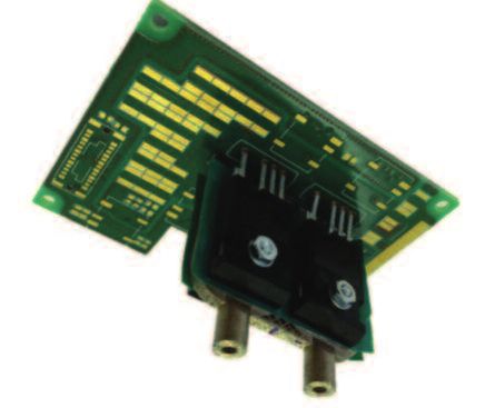
Figure 1: As gate driver, 1EDI60N12AF from Infineon
Converter is used, which is specified for high switching
electronics frequencies of up to 4 MHz and high
without inductors common-mode transients of 100 kV/s. The
integrated galvanic isolation of the gate driver
keeps the required board area small. The
drivers are supplied by one DC/DC converter
each (Murata NXE2). These small surface
mounted converters feature a coupling
capacitance of only 2.1 pF, which is of utmost
importance when high common-mode
transients are applied. The common-mode
current through the isolation barrier is directly
proportional to the voltage slope and the
parasitic coupling capacitance. Therefore, the
coupling capacity has to be kept small in the
presence of high common-mode transisients.
The gate drivers and the DC/DC
Issue 4 2018 Power Electronics Europe www.power-mag.com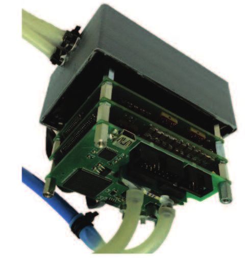
www.isea.rwth-aachen.de PCIM 2018 BEST PAPER 3
Figure 2: version of the cooler were produced and
Converter characterized. While the first nickel prototype
including potted still has a weight of 20.2 g, which
inductors corresponds to 2.7 % of the total converter
weight including inductors, the even smaller
version weights only 16.6 g. Both cooler
sizes are designed to dissipate 400 W of
losses. The reduced weight and height of the
smaller version results in a significantly
shorter production time and, due to the SLM
(Selective Laser Melting) process, production
time contributes most to the cooler costs.
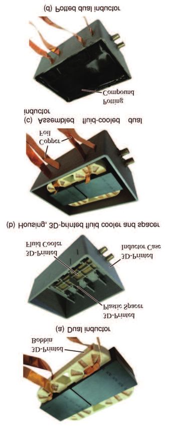
Fluid cooled inductors
A water cooled set of boost inductors was
developed, featuring various advantages
compared to classic (litz) wire wound
approaches. The inductors share a common
3D-printed plastic bobbin which serves as
place holder and isolation for the used
copper foil.
The inductors are potted together with a
3D-printed fluid cooler for efficient cooling
converters are mounted directly above one To obtain a high PWM resolution, four within minimum space. For an optimal
another on opposing board sides. This keeps high-speed clocks are used within the FPGA result, potting is done in a vacuum chamber
the kelvin source referenced copper islands, each of which is phase-shifted by 90°. These to extract all enclosed air from the potting
which are directly connected to the switching clocks are fed into an asynchronous output compound. The internal structure of the dual
node, very small (less than 1 cm2 ) and, logic which generates the required PWM inductor is depicted in Figure 4. The copper
therefore, minimizes their parasitic pulses with a resolution four times higher foil is placed inside the spiral slot of the 3D-
capacitance. The contribution of the PCB than achievable by a single clock of the same printed plastic bobbin before the 3D-printed
cannot be neglegted as only 1 cm2 of copper frequency. In the presented converter design, top plate is fitted to serve as an isolation to
with a distance of 300 m in FR4 results in a a PWM resolution of 1.25 ns is realized. the top ferrite core half.
capacitance of 12.4 pF, which is nearly six Both inductors share one common 3D-
times the coupling capacitance of the used 3D printed fluid coolers printed fluid cooler. In order to reduce eddy
DC/DC converters. The 3D-printed fluid coolers are designed to currents in the metallic cooler induced by the
Galvanically isolated current sensors with achieve space efficient cooling of four power winding parts which are not surrounded by
a band-width of 1 MHz and a small footprint transistors in a TO-247 or TO-220 package. ferrite material, the cooler is dimensioned
(SO-8) are used for each phase of the Due to 3D-printing, the shape of the fluid slightly smaller than the ferrite cores. cooled
converter (AllegroACS730). The acquired cooler can be adopted to fit nearly any other inductors. A plastic spacer is fitted between
signals are fed through fully-differential filter transistor package or other geometric the metallic 3D-printed water cooler and the
stages into a high-speed ADC, which constraints. A clear view on the 3D-printed inductors in order to further minimize eddy
features a differential input and LVDS fluid cooler with mounted SiC MOSFETs is currents. This spacer also serves as a
outputs for a high signal integrity (Linear shown in Figure 3. separator between the two ferrite cores.
Technology LTC2311-12). High- The fluid coolers are produced from nickel Tolerances during production can be kept
precisionoptocouplers (Broadcom ACPL- which represents a good compromise extremely small with the use of modern high
C87A) are used to isolate the input and between mechanical robustness and precision 3D printers (Figure 5). As a
output voltage measurement circuit from the thermal conductivity. In order to compare consequence, the two integrated inductors
control logic. different materials for the miniature fluid feature nearly identical characteristics, which is
As input and output capacitance, 184 cooler, also a stain-less steel and a copper beneficial in terms of current distribution
ceramic SMD capacitors in 1812 package
are used which are distributed over the PCB Figure 3: 3D-printed
and interconnected by four to six interleaved water cooler with
power planes for a minumum DC link mounted SiC power
inductance. This leads to a total input transistors
capacitance of 16.2 F and a total output
capacitance of 7.6 F.
A low-cost Spartan 6 FPGA is used for
control purposes. It reads out the ADCs for
current and voltage measurements and
generates the gate signals for the power
transistors. A low-cost Cortex-M0+ MCU is
used as a USB-to-SPI bridge for
communication with a PC. As the control
logic is isolated from the power electronics,
the communication can be realized without
any isolation.
www.power-mag.com Issue 4 2018 Power Electronics Europe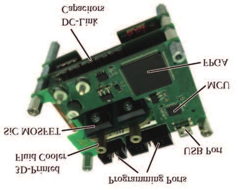
4    PCIM 2018 BEST PAPER                                                                                                           www.isea.rwth-aachen.de

                    between the phases of a multi-phase                 ABOVE: Figure 4:
                    converter.                                          Internal structure of
                                                                        the liquid cooled dual
                    Experimental results                                inductor
                    In order to characterize the 3D-printed fluid
                    coolers produced from different materials,
                    four MOSFETs are mounted on each version.
                    An electrically isolated thermal interface
                    material (TIM) is used to prevent short circuits
                    between the transistors. K-Type
                    thermocouples are used to measure the fluid
                    temperatures in the inlet and in the outlet of
                    the cooler as well as the cooler temperature.
                    The internal body diodes of the transistors are
                    used to generate controllable losses.
                       Efficiency measurements have been
                    conducted at a high switching frequency of
                    400 kHz and input voltages of 200 V and
                    400 V. The duty cycle was kept constant at 50
                    %. During the first measurements, the power
                    was limited to 15 kW by the used power
                    source. Efficiency measurements for higher
                    output powers were conducted in a back-to-
                    back configuration. The auxiliary converter is
                    operated as a controllable current sink and
                    feeds energy back to the 400 V input DC rail.
                    In this configuration only system losses of the
                    two converters have to be covered by the                  RIGHT: Figure 5:
                    power source. At output power of 19.8 kW, a           Production steps for
                    total loss of approx. 600 W can be dissipated        the fluid-cooled dual
                    effectively with the two 3D-printed fluid                   boost inductor
                    coolers.
                                                                        due to the use of 3D-printed bobbins              transistors and the power inductors as well.
                    Conclusion and outlook                              equipped with copper foil which is very           Also, the volume filled with potting compound
                    A highly compact and light-weight 19.8 kW           beneficial in a multi-phase converter.            can be decreased, which significantly reduces
                    bidirectional boost converter operated at a             Measurement results show high                 the weight. The thermal performance of the
                    very high switching frequency of 400 kHz            efficiencies over a wide load range even          transistor cooler can be enhanced further
                    using discrete SiC MOSFETs has been                 though the converter is operated at a very        more by a ceramic coating on the surface of
                    presented. With a total converter volume of         high switching frequency. 3D-printed fluid        the 3D-printed fluid cooler, which allows the
                    0.47 dm3 and a total converter weight of 735        coolers allow space efficient cooling of power    use of a TIM.
                    g, it features a very high power density of         electronic components and can be shaped to
                    42.1 kW/dm3 and 26.9 kW/kg. This is                 fulfill nearly any geometric constraint. Highly   Literature
                    enabled by the use of 3D-printed water              compact power converters with very high              “Highly Integrated Two-Phase SiC Boost
                    coolers for the power transistors, as well as for   power densities can be realized by the use of     Converter with 3D Printed Fluid Coolers
                    the potted inductors. These inductors are           miniature fluid coolers. The converter size can   and 3D Printed Inductor Bobbins”, PCIM
                    developed and optimized for high-frequency          be reduced further more by the use of a           Europe 2018 Proceedings, pages 317 -
                    operation and show excellent reproducibility        shared 3D-printed fluid cooler for the power      324

Issue 4 2018 Power Electronics Europe                                                                                                        www.power-mag.com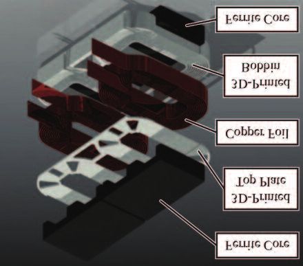
You can also read