Volume 10, Issue 3, March 2021 - IJAREEIE
←
→
Page content transcription
If your browser does not render page correctly, please read the page content below

Volume 10, Issue 3, March 2021
International Journal of Advanced Research in Electrical, Electronics and Instrumentation Engineering (IJAREEIE)

                  | e-ISSN: 2278 – 8875, p-ISSN: 2320 – 3765| www.ijareeie.com | Impact Factor: 7.122|

                                        ||Volume 10, Issue 3, March 2021||

                                    DOI:10.15662/IJAREEIE.2021.1003030

  Design of Dynamic Current Mode Multi-Cell
     Charger by Cell State Synchronization
                                  S.Ganesamurthy1 , Dr.A.Kalaimurugan2 Ph.D
     M.E [Power Electronics and Drives], Dept. of EEE, Agni College of Technology, Chennai, Tamilnadu, India 1
              Professor, & Head, Dept. of EEE, Agni College of Technology, Chennai, Tamilnadu, India 2

ABSTRACT: Nowadays, lithium-ion (Li-ion/Polymer) batteries are playing a substantial role in energy storage
solutions for modern-day consumer products such as mobile phones, laptop computers, EVs and portable devices. In
This Scenario Overcharging and over-discharging cells can lead to damage, resulting in battery fires, capacity reduction
or reduced lifetime. Conventional BMS devices addresses safety and reliability concerns by providing measurements
that ensure each cell is functioning within a constrained operating range. But it is not giving clear communication to the
Battery Charger about the regulated charge control to the battery Stack. So, in this system proposes the Internal Cell
State Based Dynamic Current Mode Multi-Cell Charge by Cell State Synchronized PWM Control.

KEYWORDS: Li-ion, battery charger, BMS, multi-cell, PWM.
                                                    I. INTRODUCTION
The challenges in battery monitoring charging and arise due to the fact that the chemical process involved in generating
the electrical energy cannot easily be expressed in terms of parameters of a model and the model itself, will be different
for different conditions of the battery and for different external triggers like current, voltage and load. Batteries are used
either as a primary or as a secondary storage of energy for Processing Industries, EVs, Auto Industries and Portable
Devices. The secondary storage batteries are subjected to charging and discharging cyclically. The
charging/discharging cycles degrade the performance of the battery, thus reducing its efficiency in terms of capacity to
hold charge. Since batteries operate by converting the chemical energy in the electrolyte into electrical energy, the
degradation affects the chemical reactions as well as the interaction between electrode plates and the electrolyte. The
latter is also due to deposition on the electrodes. The battery performance is also affected due to agin g.

The performance degradation of a battery needs to be monitored so that once the performance in terms of storage
capacity and energy delivery falls below a threshold, the battery can be replaced. The performance degradation of a
battery is measured in terms of state-of- charge (SOC), Voltage and Current. The SOC is the total amount of charge left
in the battery, and is expressed in terms of percentage of the total charge that the battery in its present condition can
hold. The SOH is the percentage of the total charge of a fully charged new battery that a fully charged battery in the
current condition can hold.Battery Management systems (BMS) are developed to monitor the battery condition to
improve the battery charging operation. And it leads to extend the life of Cell. The BMS is also used to keep track of
charging/discharging of the batteries as well as management of sources of energy and loads.

In this paper, addresses some issues in BMS, mainly on Charge control, Cell Voltage monitoring, Temperature
monitoring, continuous load monitoring. Rapid advancements in Li-ion/Li Polymer battery technology have resulted in
high specific power/energy, high terminal voltage, higher efficiency and long cycle life. Therefore, Li-ion/Li Polymer
batteries have become standard in electric vehicles, Automotive/Processing industries, Renewable energy and other
Portable applications. Most of the battery powered applications comes with a battery management system (BMS) which
determines the battery states such as state of charge (SOC) and state of health (SOH) and controls the charge/discharge
rates to enhance the life of the battery But in this project taken care about all the parameters of the cells like Cell
Voltage, Cell temperature, Internal Impedance of the Cell, SOC and SOH with load and without load conditions. Based
On these Conditions the design of dynamic current mode multi-cell charger by cell state synchronization through the
Fuzzy logic algorithm.

IJAREEIE © 2021                                 |   An ISO 9001:2008 Certified Journal |                                 747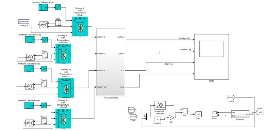
International Journal of Advanced Research in Electrical, Electronics and Instrumentation Engineering (IJAREEIE)

                 | e-ISSN: 2278 – 8875, p-ISSN: 2320 – 3765| www.ijareeie.com | Impact Factor: 7.122|

                                     ||Volume 10, Issue 3, March 2021||

                                  DOI:10.15662/IJAREEIE.2021.1003030
                               II. SMART BATTERY MANAGEMENT SYSTEMS

The task of battery management systems is to make sure the optimal use of the residual energy present during
a battery. So as to avoid loading the batteries, BMS systems protect the batteries from deep discharge, from over
voltage, which are results of utmost fast charge and extreme high discharge current. Within the case of multi-
cell batteries, the battery management system also provides for cell balancing function, to manage that different
battery cells have same charging and discharging requirements.

The multi-channel battery monitoring and balancing system is meant for Li-Ion battery packs utilized
in automotive, industrial and consumer applications. It fulfils four main functions: cell voltage measurement,
temperature     measurement,     cell    balancing,   isolated   communication    to   main    battery  charging
controller. Additionally, it provides the required diagnosis tools to make sure proper function of the controlled
battery, because the Active thermal control may be a key element within modern Li-Ion battery packs as cell
temperature for charging has got to be kept between 0 to 45°C and for discharging between -20 to 60°C;
operation outside these ranges leads to accelerated aging, reduced capacity or maybe full damage of the battery.

                                                 III.SYSTEM THEORY

Rapid advancements in Li-ion/Li Polymer battery technology have resulted in high specific power/energy, high
terminal voltage, higher efficiency and long cycle life. Therefore, Li-ion/Li Polymer batteries have become standard in
electric vehicles, Automotive/Processing industries, Renewable energy and other Portable applications. Most of the
battery powered applications comes with a battery management system (BMS) which determines the battery states such
as state of charge (SOC) and state of health (SOH) and controls the cha rge/discharge rates to enhance the life of the
battery. In this paper taken care about all the parameters of the cells like Cell Voltage, Cell temperature, Internal
Impedance of the Cell, SOC and SOH with load and without load conditions. Based On these Co nditions the design of
dynamic current mode multi-cell charger by cell state synchronization through the Fuzzy logic algorithm.

The design of dynamic current mode multi-cell charger by cell state synchronization is a Multi cell battery charger
CC/CV Power Supply unit consists of BMS cum battery charger. Based on The BMS feedback output Signal to the
battery Charger output current is controlled. The block diagram is shown in Fig.1.

                    CELL V
        f4S                                      MCU
                    CELL I                Internal Res Cal &
       CELL                                Event Monitoring
                   CELL Temp
                   Discharge I                  FCL FB
                                                 PWM                          DISPLAY

                                                  Fig.1. Block Diagram
This paper designed based on the flyback topology. Due to Multi cell stack charging with linear charging describes the
steps taken to design, build and test a 20W Flyback Switched Mode Power Supply (SMPS) that uses the CC to control
the circuit. The reason for changing the dedicated feedback controller to an MCU with CIPs is to gain control,
monitoring, communications and automated features, which are some of the demands in a new SMPS. Designers who

IJAREEIE © 2021                              |   An ISO 9001:2008 Certified Journal |                              748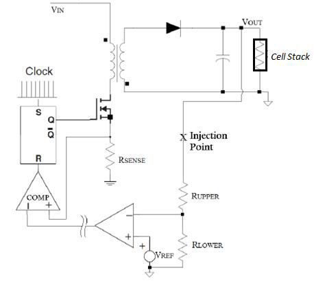
International Journal of Advanced Research in Electrical, Electronics and Instrumentation Engineering (IJAREEIE)

                 | e-ISSN: 2278 – 8875, p-ISSN: 2320 – 3765| www.ijareeie.com | Impact Factor: 7.122|

                                      ||Volume 10, Issue 3, March 2021||

                                   DOI:10.15662/IJAREEIE.2021.1003030
have used only Application Specific Integrated Circuits (ASICs) may think of them as analogue devices, such as op
amps and comparators that are integrated in a Single IC that does not need code supervision to work normally, but can
be Interconnected and configured in a sandbox-type environment.
At the start of a cycle, the IC oscillator sets the SR latch and turns on the external power MOSFET.If the load current
increases, the output voltage decreases slightly, causing the FB pin voltage to fall below the 800mV reference.
Conversely, if the load current decreases, the FB voltage rises above the mV reference and the error amplifier sinks
current away from the ITH pin causing its voltage to fall. If the current comparator does not trip, This IC automatically
limits the duty cycle to 80%, resets the SR latch, and turns off the external MOSFET. For example, if the load current
increases, the output voltage decreases slightly, and sensing this, the error amplifier sources current from the ITH pin,
raising the current comparator threshold.

                                          IV. RESULT AND DISCUSSION

The Conceptual Blocks created based technical function of AC to DC battery charger and BMS. The simulation block
is shown in Fig.2.

                                             Fig.2. Simulation BMS model

The BMS control PWM signal from the MCU is comprised of Cell’s SOC, SOH Cell Voltage, Discharging Current,
Temperature and internal resistance. Based on This Error Signal Simulated output shown in Fig.3and without Error
BMS output signal Generated output is shown in Fig.4.

 Fig.3. Current and Voltage wave form is output of the battery charging unit Injected by the PWM input derived from
                                           the Error Signals of the BMS

IJAREEIE © 2021                               |   An ISO 9001:2008 Certified Journal |                               749
International Journal of Advanced Research in Electrical, Electronics and Instrumentation Engineering (IJAREEIE)
| e-ISSN: 2278 – 8875, p-ISSN: 2320 – 3765| www.ijareeie.com | Impact Factor: 7.122|
||Volume 10, Issue 3, March 2021||
DOI:10.15662/IJAREEIE.2021.1003030
Fig.4. Current and Voltage wave form is output of the battery charging unit Injected by the PWM input derived from
the Error Free Signals of the BMS
The battery charger designed simulation blocks is shown on Fig.5.
Fig.5. Battery Charger Simulation Blocks
IJAREEIE © 2021 | An ISO 9001:2008 Certified Journal | 750International Journal of Advanced Research in Electrical, Electronics and Instrumentation Engineering (IJAREEIE)
| e-ISSN: 2278 – 8875, p-ISSN: 2320 – 3765| www.ijareeie.com | Impact Factor: 7.122|
||Volume 10, Issue 3, March 2021||
DOI:10.15662/IJAREEIE.2021.1003030
The Battery Cell Charging Profile Period is shown on the Fig.6.
2C /Fast 90 – 100%
Fig.6. Conceptual Charging Profile Period
V. CONCLUS ION
The Battery Charger cum Smart Battery Management systems concepts and Hardware Blocks are created Based on the
BMS’S Measurement Signals of Cell Voltage, Cell Current, Temperature and State of Charge. These are member
functions of the Fuzzy logic system. The Fuzzy derived output control signal is converted into Switching PWM. This
PWM signal is High frequency; the signal-controlled results are validated on the simulation of the power supply section
and BMS. This Type of charging Profile will reduce the temperature rises in the charging and Discharging of Battery
stacks easily identifies the less Voltage cells and State of the Charge. This will improve the life cycle efficiency the
Multi cells also Reduces the Burst happenings of the cells during charging or discharging period.
REFERENCES
[1] M.GuneyandY.Tepe,"Classificationandassessmentofenergystoragesystems",Renewable and Sustainable Energy
Reviews, vol. 75, pp. 1187-1197,2017.
[2] K. Divya and J. Ostergaard, "Battery energy storage technology for power systems —An overview", Electric
Power Systems Research, vol. 79, no. 4, pp. 511-520,2009.
[3] H. IBRAHIM, A. ILINCA and J. PERRON, "Energy storage systems —Characteristics and comparisons",
Renewable and Sustainable Energy Reviews, vol. 12, no. 5, pp. 1221-1250, 2008.
[4] J.Chetaks, K. Kalaitzakis, N. Voulgaris and S. Manias, "Designing a new generalized battery management
system", IEEE Transactions on Industrial Electronics, vol. 50, no. 5, pp. 990- 999,2003.
[5] M.KianiandJ.Evans,"AnewApproachforManagementofbatterystoragesystemsformobile and stationary
applications",2015.
[6] A.SzumanowskiandYuhuaChang,"BatteryManagementSystemBasedonBatteryNonlinear Dynamics Modeling",
IEEE Transactions on Vehicular Technology, vol. 57, no. 3, pp.1425- 1432,2008.
[7] R. Kaiser, "Optimized battery-management system to improve storage lifetime in renewable energy systems",
Journal of Power Sources, vol. 168, no. 1, pp. 58-65,2007.
[8] F.Camci,C.Ozkurt,O.TokerandV.Atamuradov,"SamplingbasedStateofHealthestimation methodology for Li-ion
batteries", Journal of Power Sources, vol. 278, pp. 668-674,2015.
[9] M. Berecibar, I. Gandiaga, I. Villarreal, N. Omar, J. Van Mierlo and P. Van den Bossche, "Critical review of
state of health estimation methods of Li-ion batteries for real applications", Renewable and Sustainable Energy
Reviews, vol. 56, pp. 572-587,2016.
[1 0] H.Ikeda,S. Minami, S.Hou, Y.Onishiand A. Kozawa, "Nobel High Current Pulse Charging Method for
Prolongation of Lead-acid Batteries", Journal of Asian Electric Vehicles, vol. 3, no. 1, pp. 681-687,2005.
IJAREEIE © 2021 | An ISO 9001:2008 Certified Journal | 751You can also read