GSM/GPRS Controller BieneRemote1280GM - GSM module for SMS or GPRS remote monitoring and control applications Data-Logging to EEPROM Data-Logging ...
←
→
Page content transcription
If your browser does not render page correctly, please read the page content below
GSM/GPRS Controller BieneRemote1280GM
     GSM module for SMS or GPRS remote monitoring and control applications

                                                 Data-Logging to EEPROM
                                               Data-Logging to Web-Server
                                                         Alarm Notification
                                                           Remote Control

                                                  www.bieneelectronics .com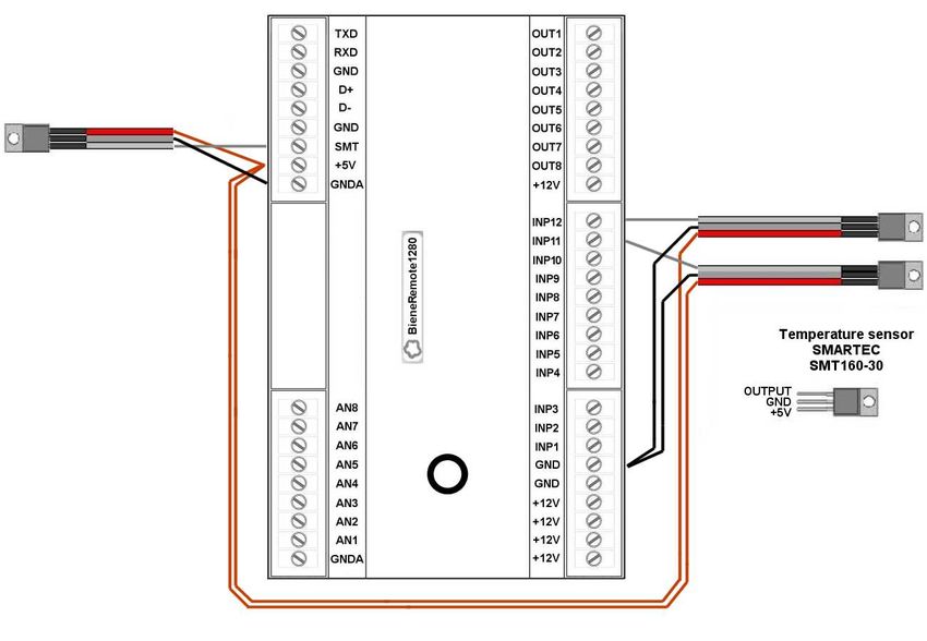
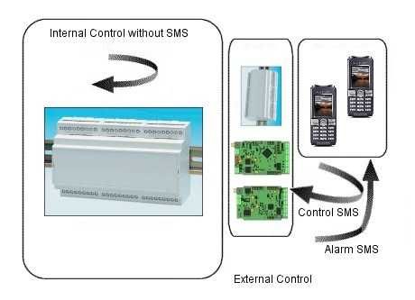
Introduction

The BieneRemote1280GM GSM/GPRS controller is a communications device that connects
used for wireless Data-Logging, Alarm Monitoring and Control of remote equipments and
systems. The BieneRemote1280GM provides logging of data to internal EEPROM memory and
to a web-server for access through a web browser. Multiple users can interrogate the
BieneRemote1280 or be notified on configurable events.

The built-in quad-band Telit GM862-QUAD GSM modem and is compatible with all 850, 900,
1800 or 1900Mhz GSM networks.

Features

•   Internal quad-band GSM-modem
•   12 digital input ports
•   8 analog input ports
•   8 digital open drain output ports
•   Up to 3 SMT160-30 temperature sensor input
•   On-board power supply monitoring
•   On-board temperature monitoring (optional)
•   Easy to programming via RS232 interface (software included) and via SMS.
•   Error notification using SMS messaging via cell phone
•   Data Logging using GPRS
•   Control via SMS
•   Cell Phone - BieneRemote Control
•   BieneRemote – BieneRemote Control
•   PC - BieneRemote Control
•   Configuration from any cell phone
•   Configuration from PC
•   Din-Rail enclosure
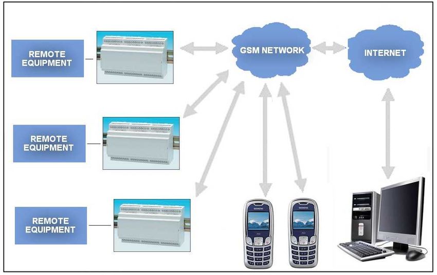
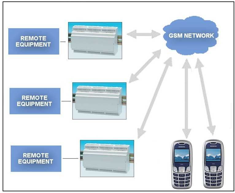
SMS and GPRS Functions

BieneRemote1280GM controller send an event SMS messages to up to 7 cell phones.
Any cell phone can be used to send SMS commands to BieneRemote1280GM.
Mobile users can contact and request information from a BieneRemote1280GM GSM controller
and up to 7 users can receive notification of events.

With the BieneRemote1280GM GSM/GPRS controller you can use a mobile phone or SMS
enabled PC to:
• Monitor the status of equipment or systems
• Send control commands to remote equipment
• Receive notification of events

Any BieneRemote1280GM GSM controller can be used to send SMS commands to other
BieneRemote1280GM GSM controller for remote control.
Any BieneRemote1280GM GSM controller can be programmed via SMS instruction.

Web server - GPRS based remote monitoring and control application.

SMS based remote monitoring and control application
Inputs

The BieneRemote1280GM has 12 voltage-free clean-contact (optional 12V or 5V power-up).
Digital Inputs can be
independently configured as:
• 0-1 and 1-0; 0-1; 1-0 event
    input
• counter input (two inputs)

The BieneRemote1280 has 8 Analog Inputs that can be independently configured as:
• 0-5 Volt 10 bit Analog Inputs
• 0-10 Volt 10 bit Analog Inputs
• 4-20mA 10 bit Analog Inputs
   (with switch)
Analog Input 8 can be used for
12V Power Supply Monitoring

                           The BieneRemote1280GM has Temperature Sensor Input for
                           Smartec SMT160-30 temperature sensor.

All Inputs states can be logged, and it can trigger alarms based on user-defined setpoints.
Alarming and user notification settings can be set for each input.
All Inputs states can be send to Web-server using GPRS-Internet network.
All inputs has screw terminal connection.

Logging settings for each input can be set to:
• Logging Disabled
• Log to EEPROM and the Internet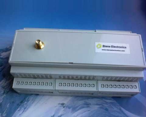
Outputs

The BieneRemote1280GM has 8 open-drain Outputs. These may be controlled with SMS
messages from approved users. Outputs states can be logged to EEPROM and the Internet.
All outputs has screw terminal connection.

Expansion Modules (optional)

The BieneRemote1280GM has connectors for additional expansion modules connection.
All 9 additional I/O has screw terminal connection.

Power Supply Monitoring

The BieneRemote1280GM operates from a 12VDC power source. The analog input 8 can be
used to monitor either analog input or 12VDC power supply voltage. An internal jumper must be
changed to select either option.

Temperature Monitoring

SMT160-30 Smartec Temperature Sensor can be connected to the Temperature Sensor Input.
The temperature can be logged, and it can trigger alarms based on user-defined setpoints. The
sensor has an accuracy of 1°C from –20 to +85°C.

Users and Administrators

The BieneRemote1280GM supports up to 7 users. Each user can interrogate the device for the
current I/O status. Users can be notified based on changes to each input or output.
Configuration tables allow inputs and outputs to be allocated to specific users (administrators).
Security

The BieneRemote1280GM has a number of in-built security features. Caller ID security provide
authentication for device interrogation and control.

Alarms

SMS messages can be sent to users when an input reaches an alarm state. The following
setpoint configurations are available:
Alarm when 0-1 event at digital input.
Alarm when 1-0 event at digital input.
Alarm when above set point at analog input.
Alarm when below set point point at analog input.
Alarm when inside set points point at analog input.
Alarm when above set point at temperature input.
Alarm when below set point point at temperature input.
Alarm when inside set points point at temperature input.

Module Programming/Configuration
The BieneRemote1280GM can be configured:
• from PC through RS232 port
• remotely with SMS command
•
Configuration options include Alarm Message Content, System Settings, Users and
Administrators Phone Numbers, and Alarm and Data-Logging Settings.

Data-Logging

                            Inputs, Outputs, Temperature, Power Voltage can be logged to the
                            128K of internal EEPROM memory and to the Web-Server. Data
                            may be accessed via the Client Website as online graphs, reports
                            and CSV downloads.
                            Inputs can be scanned up to every 60 seconds. Logging can be as
                            frequent as every 60 seconds. Different logging rates can be
                            applied when an alarm is present. Instantaneous or averaged
                            values can be logged.

Module to Module Control

T                            he BieneRemote1280GM supports Module-to-Module
                             management with SMS command.
Technical specifications

Technical             BR128GM           BR128GM-4A        BR128GM-          BR1280GM
specifications                                            4PT1000
GSM support
GSM Modem             Telit GM862-      Telit GM862-      Telit GM862-      Telit GM862-QUAD
                      QUAD              QUAD              QUAD
GSM band support      850, 900, 1800,   850, 900, 1800,   850, 900, 1800,   850, 900, 1800,
                      1900 Mhz          1900 Mhz          1900 Mhz          1900 Mhz
RF Power              Class 4 (2W)      Class 4 (2W)      Class 4 (2W)      Class 4 (2W)
                      850Mhz,900Mhz,    850Mhz,900Mhz,    850Mhz,900Mhz,    850Mhz,900Mhz,
                      Class 1 (1W)      Class 1 (1W)      Class 1 (1W)      Class 1 (1W)
                      1800Mhz,          1800Mhz,          1800Mhz,          1800Mhz, 1900Mhz
                      1900Mhz           1900Mhz           1900Mhz
GPRS               Class 10             Class 10          Class 10          Class 10
Antenna Connection 50Ω SMA (f)          50Ω SMA (f)       50Ω SMA (f)       50Ω SMA (f)
                   Connector            Connector         Connector         Connector
Gateway Functions
Remote Parmeter   The value of any The value of any       The value of any The value of any
Reading           parameter can be parameter can be       parameter can be parameter can be
                  requested from a requested from a       requested from a requested from a
                  GSM mobile       GSM mobile             GSM mobile       GSM mobile
Remote Parameter      The value of any The value of any   The value of any The value of any
Setting               parameter can be parameter can be   parameter can be parameter can be
                      set from a GSM set from a GSM       set from a GSM set from a GSM
                      mobile           mobile             mobile           mobile
Trigger Conditions    -                -                                   Any parameter
                                                                           specified as being  a user
                                                                           programmed value
Trigger Qualify Time -                  -                                  Programmable from
                                                                           0-99 seconds
Trigger Re-arm Time -                   -                                  Programmable from
                                                                           0-99 minutes or re-
                                                                           arm from remote
                                                                           command
Programmable alarm Up to 44 alarm Up to 44 alarm          Up to 44 alarm Up to 44 alarm
message            message can be message can be message can be message can be
                   programmed to programmed to programmed to programmed to any
                   any or all of 7+1 any or all of 7+1 any or all of 7+1 or all of 7+1 different
                   different GSM     different GSM        different GSM    GSM numbers
                   numbers           numbers              numbers
Programmable GSM Up to 7             Up to 7              Up to 7          Up to 7
Tel.numbers
Administration     All functions of  All functions of the All functions of All functions of the
                   the SMS module SMS module can the SMS module SMS module can be
                   can be            be administered can be                administered from a
                   administered      from a GSM           administered     GSM mobile
                   from a GSM        mobile               from a GSM
                   mobile                                 mobile
Security           Incoming          Incoming requests Incoming            Incoming requests
                   requests or       or commands can requests or           or commands can
                   commands can be accepted only commands can be accepted only
                   be accepted only from designated be accepted only from designated
                   from designated mobile numbers from designated mobile numbers
                   mobile numbers                         mobile numbers
Technical         BR128GM               BR128GM-4A        BR128GM-          BR1280GM
specifications                                            4PT1000
SMS alarm message Yes                   Yes               Yes               Yes
SMS control          Yes                Yes               Yes               Yes
Services phone       5                  5                 5                 5
numbers
Administration phone 3                  3                 3                 3
numbers
User-defined alarm     Yes              Yes               Yes               Yes
messages
GPRS/FTP               Yes              Yes               Yes               Yes
Call support           none             none              none              none
Inputs
Digital inputs         7 npn (sink)     7 npn (sink)      7 npn (sink)      12 npn 12VDC
                       12VDC            12VDC             12VDC
Optoisolated inputs    none             none              none              Additional order
Counter                none             none              none              2 inputs can
                                                                            function as 16bit
                                                                            resolution counter
                                                                            inputs (optional)
Analog inputs          Four 10-bit      Four 10-bit inputs: Four 10-bit     Eight 10-bit inputs:
                       inputs: 0-5V     0-10V / 0-5V        inputs:         0-10V; 0-5V;
                       unprotected      (0-20mA, 4-20mA 0-10V / 0-5V        0-20mA; 4-20mA
                                        optionally)         (0-20mA, 4-20mA (with switch
                                                            optionally)     selectable)
Temperature        none                 none                4 PT1000 inputs 1 SMT30-160 input
measurement inputs                                          (PT100          + 2 SMT160-30
                                                            optionally)     connected to Input
                                                                            11 & 12
Temperature            -                -                   -99...+149oC    -45...+135oC
measurement range
Temperature sensor -                    -                 2 or 4-wire       Up to 3
                                                          PT1000            SMT30-160
                                                                            (Smartec)
Input impedance        0-5V: 100MOm     0-10V/0-5V:       0-10V / 0-5V:      0-10V / 0-5V:
                                        100kOm            50kOm              50kOm
                                                                             0-20mA / 4-20mA:
                                                                             249 Om
Digital input event    0-1 or 1-0        0-1 and 1-0       0-1 and 1-0       0-1 and 1-0
Analog input event     below min / min/ below min / min/ below min / min / min / norm / max
                       norm / max / over norm / max / over norm / max / over
                       max               max               max
Temperature input      -                 -                 below min / min / min / norm / max
event                                                      norm / max / over
                                                           max
Digital input filter   -
Analog input filter    -
Temperature input      -                 -
filter
Sampling Rate

Outputs
Technical              BR128GM            BR128GM-4A BR128GM-                   BR1280GM
specifications                                       4PT1000
Open drain MOSFET      4              4              4                          8
outputs                20V max        20V max        20V max                    50V max
Relay outputs          1 (NO/COM/NC), 1 (NO/COM/NC), 1 (NO/COM/NC),             Additional order
                       24VDC/120VAC/ 24VDC/120VAC/ 24VDC/120VAC/
                       0.5A           0.5A           0.5A

PWM outputs            none               none               none               Additional order

Analog outputs         none               none               none               Additional order
Digital output control On-Off or Time     On-Off or Time     On-Off or Time     On-Off
                       Proportional       Proportional       Proportional
Alarming
                       Yes                Yes                Yes                Yes
SMS alarm message
User-defined           Yes                Yes                Yes                Yes
messages
Phone number
Services phone         5                  5                  5                  8
numbers
Administration phone 3                    3                  3                  3
numbers
Control
SMS control            Yes                Yes                Yes                Yes
Call support           none               none               none               Yes
                                                                                (status request)
Communications
GPRS/FTP               Yes                Yes                Yes                Yes
Serial                 RS232;             RS232;             RS232;             RS232;
communications         RS485 optionally   RS485 optionally   RS485 optionally   RS485 optionally
MODBUS                 none               none               none               Additional order
Function
Data logger function   Yes                Yes                Yes                Yes
EEPROM memory for      64Kbyte            64Kbyte            64Kbyte            128Kbyte
data logging
Human - Module         Yes                Yes                Yes                Yes
control
Module - Module        Yes                Yes                Yes                Yes
control (outside)
Module - Module        Yes                Yes                Yes                Yes
control (inside)
Control
Module Control         via SMS            via SMS            via SMS            via SMS
Programming
Module programming     RS232 port,        RS232 port,        RS232 port,        RS232 port,
                       via SMS            via SMS            via SMS            via SMS

Muscelaneus
Technical BR128GM BR128GM-4A BR128GM- BR1280GM
specifications 4PT1000
Real Time Clock none none None date and time, 3V
lityum battery
On-board monitoring none none none +12VDC power
supply monitoring;
board temperature
monitoring
(optional)
Buzzer output none none none Additional order
I/O expansion option optional none none Up to 7 additional
I/Os (Additional
order)
Wiring Connections Screw terminals Screw terminals Screw terminals Screw terminals
Wire range - Wire range - Wire range - Wire range -
26-16 AWG 26-16 AWG 26-16 AWG 24-12 AWG
1.5 mm2 1.5 mm2 1.5 mm2 2.5 mm2
Electrical
Power supply 12VDC, 12VDC, 12VDC, 12VDC, 70mA
70mA standby, 70mA standby, 70mA standby, standby, 500mA
500mA (rms), 500mA (rms), 500mA (rms), (rms) max, 2A peak
2A peak 2A peak 2A peak
Environmental
Operating 0 to +50°C 0 to +50°C 0 to +50°C 0 to +50°C
temperature
Extended operating -20 to +70°C -20 to +70°C -20 to +70°C -20 to +70°C
temperature
Storage Temperature -40 to +85°C -40 to +85°C -40 to +85°C -40 to +85°C
Humidity 0-95% non- 0-95% non- 0-95% non- 0-95% non-
condensing condensing condensing condensing
Dimensions
Dimensions 65x100 65x100 65x100 155x87
(mm x mm)
Enclosure optional none none DIN-rail mounting
Enclosure dimensions 160x90x58
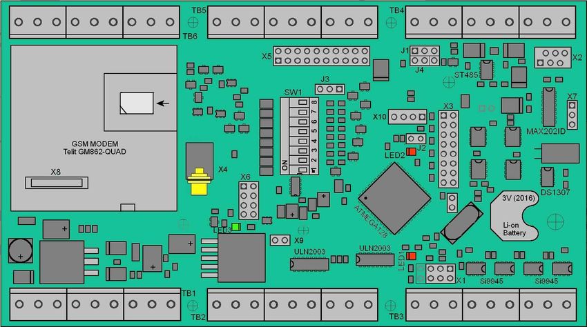
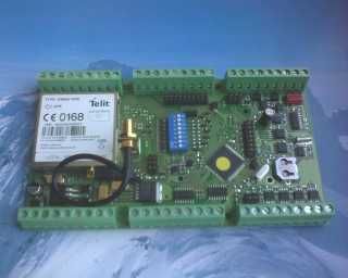
Weight (kg)Hardware The BieneRemote1280GM module consists of the microprocessor, voltage regulator, inputs driver, MOSFET output driver, RS232 and RS485 interface (optional), built-in GSM module with SIM header, GSM antenna connector and screw terminals for external power supply and for input and output signal connection. Power Supply The BieneRemote1280GM operates from a 12VDC power source. It draws less then 70mA standby, less then 350mA rms and 2A peak max. 12VDC/1.7A...2A switching stabilized power supply is recommended. Power supply input has reverse polarity and overvoltage protection.
SIM Card
Small SIM-card with 3V or 1,8V technology

Preparation of SIM card

•     Delete any SMS messages from SIM.
•     Write SMS message to SIM (for standard version only)
•     Disable PIN code request so it will not prompt for a PIN code on turning on.
•     Write 3 authorized numbers to Phone Book (position 1,2,3)
      You can to position 1 write number 99 or +99 – for disable authorization numbers

      Note:
      • The BieneRemote1280GM can only be used with small SIM-cards with 3V or 1,8V
         technology.
      • For SIM card preparation you can use cell phone or external GSM modem.
      • SIM card change if power turn off.

LED indicators

•     Module status indication - RED LED (LED1)
•     RED LED (LED2) – for additional use
•     GSM Modem GM862 status indication - GREEN LED (LED3)

      Module LED indication (Red LED)

    LED status                                   Modem status
    Permanently off                              Device off
    Short blinking after power on and after 1    SIM card read process
    min periodic blinking
    Short blinking                               Module in work
    Permanently on                               Module work with modem

      GSM Modem LED indication (Green LED)

    LED status                                   Modem status
    Permanently off                              Device off
    Fast blinking (period 1s, ton 0,5s)          Net search / Not registered / Turning off
    Slow blinking (period 3s, ton 0,3s)          Registered full service
    Permanently on                               A call is active
Connectors and Jumpers
• Power supply connection (TB1 - screw terminal block).
• Controlled equipment digital inputs and outputs connection (TB2,TB3 - screw terminal block)
• Controlled equipment analogue inputs connection (TB6 - screw terminal block)
• Additional inputs/outputs for use with additional adapters connection (TB5 - screw terminal
block) – optional
• SMA female connector X4 for GSM antenna connection.
• Additional pin header connectors for additional adapter connection X3,X5,X6,X9.- optional
• RS-232 interface connector TB4 (X2 – additional 6-pin Micro-Match connector).
• RS-485 interface connector (TB4 - screw terminal block)..
Power Supply Connection
+12VDC stabilized Power Supply must be connected with screw terminal block.
We recommend use stabilized 1,7...2A 12VDC power supply.
Power supply input has negative voltage and over voltage protection.
Internal +12VDC connection and Power Supply connection
schematic (TB1).Antenna connection GSM antenna must be connected to SMA connector X4. Use only the 50Om antenna of the necessary frequency range. Base version complected with direct mount GSM antenna. Note: It is very important that the antenna is installed on a location where the GSM-network coverage is sufficient. Please also check carefully that antennas are not installed nearby technical devices, cables etc which could influence the GSM-radiation. SIM card insertion SIM card holder built-in GM862 module. It is inserted in GM862 modems push-push system.
Inputs and Outputs connection

Inputs and outputs must be connected with screw terminal blocks TB2,TB3,TB6.

Screw terminal block for wire range - 24-12 AWG; 2.5 mm2

Note: See also "Inputs and Outputs schematic".
Connectors

For Power supply, Inputs and Outputs connection used screw terminal blocks.

               Without Extension Board                   With Extension Board (optional)

+12V                 -      +12VDC Power Supply input / +12VDC output
GND                  -      GND
INP1...INP12         -      Digital Inputs 1 – 12 (input11&12 can be use for SMT160-30
                            temperatute sensor connection
OUT1...OUT8          -      Output 1 – 8
TXD                  -      RS232 interface Transmit Data (output)
RXD                  -      RS232 interface Receive Data (input)
D+                   -      RS485 interface (optional)
D-                   -      RS485 interface (optional)
+5V                  -      +5V output (50mA max)
SMT                  -      external Smartec SMT160-30 temperature sensor input
AN1...AN8            -      Analog Inputs 1 - 8
GNDA                 -      Analog GND
EXT1...EXT9          -      Additional I/O (with extension board only)
X1 - not used (ISP interface connector)
X2 - additional 6-pin Micro-Match RS232 connector
X3 - pin header connector for additional adapters connection
X4 - SMA female connector for GSM antenna connection
X5 - pin header connector for additional adapters connection
X6 - pin header connector for additional adapters connection
X7 - not used
X8 - 50-pin Molex connector for Telit GM862 module connection
X9 - pin header power connector for additional adapters connection
TB1,TB2,TB3,TB4,TB6 - terminal blocks for external power supply, digital and
analog inputs, outputs, RS232 or RS485 connection
TB5 - terminal blocks for additional I/O with extension boardInterface
RS232 interface
Connection to PC with standard RS232 interface.
Connection to external device with standard RS232 interface.
BieneRemote1280GM has alternative 6-pin Micro-Match connector
(X2) for RS232 interface.
X2 BR1280GM PC
1 NC NC
2 RXD TXD
3 GND GND
4 TXD RXD
5 NC NC
6 NC NCRS485 interface (optional) Not used in base version. ISP interface Standard 2x3 pin header ISP interface connector X1. Used only for in-system ATMEGA128 microcontroller programming. Pin Pin 1 TXD0 2 VCC 3 SCK/ 4 RXD0 5 Reset/ 6 GND Note: Not for user.
Additional adapters interface (not used in base version)

Pin headers X3, X5, X6, X9 used for additional adapters connection.

X3       -     2x8 pin header (microcontroller I/O lines) for adapter connection.
X5       -     2x10 pin header (external I/O signals) from adapter to X14 screw terminal block
               connection.
X6       -     2x3 pin header (audio signals from GM862) for adapter connection.
X9       -     2x1 pin header (+12V power supply) for adapter connection.

Microcontroller port
  X3                    X3
     1       +5V         2         (AREF)
     3       PC6         4          (PB0)
     5       PC5         6          SCL
     7       PC4         8          SDA
     9       PC3         10        GNDA
  11         PC2         12        GNDA
  13         PC1         14        GNDA
  15         PC0         16        GNDA
GM862 Audio line X6 X6 1 EAR_MT- 2 PWRCTL 3 EAR_MT+ 4 MIC_MT+ 5 MIC_MT- 6 GND +12V Power Supply X9 X9 1 GND 2 +12V I/O line X5 X5 1 I/O_1 2 I/O_1 3 I/O_2 4 I/O_2 5 I/O_3 6 I/O_3 7 I/O_4 8 I/O_4 9 I/O_5 10 I/O_5 11 I/O_6 12 I/O_6 13 I/O_7 14 I/O_7 15 I/O_8 16 I/O_8 17 I/O_9 18 I/O_9 19 GNDA 20 GNDA
Inputs / Outputs Schematic

Inputs

Digital Transistor Inputs

Connector: Screw terminal block
Inversion: Yes
Protection: Yes
Max input voltage: +12V without external limited resistor.
Free Input: logic "0"
Logic "0": 0V…+1V
Logic "1": +1.5V…+12V

Note: 2.2kOm resistor mounted for INP1...INP10 only, INP11, INP12 without pull-up resistors
0-10V / 0-5V Analog Inputs

Connector: Screw terminal block
Input type: CMOS
Input Voltage: 0 to +10V
Protection: Yes
Input resistance: 50 KOm.
ADC resolution: 10-bit

Note: 249Om resistor can be with switch SW1 connected for 0-20mA / 4-20mA input mode (for
each analog inputs individual).

Temporature sensor input

Connector: Screw terminal block
Sensor type: Smartec SMT160-30
Input type: CMOS
Input Voltage: 0 to +5V
Protection: Yes
Outputs

MOSFET Open Drain Outputs

Connector: Screw terminal block
MOSFET transistor: Si9945 or IRF7103
Max. Voltage: 50V
Connection Example

Connection example to Input Driver

Use only A connection for INPUT1...10 in default mode. B, C, D connection can use for
INPUT11,12. For B,C,D connection to INPUT1...10 need remove pull-up resistors R38-R47 from
back side of board.

                                                  Select power supply for all inserted
                                                  pull-up resistors:
                                                  R50 0Om resistor/jumper – to +5V.
                                                  R51 0Om resistor/jumper – to +12V.
                                                  (R50 – not mounted)

Note 1:
In this version 10 Inputs (INP1-INP10) connected via 2k2 Pull-Up resistors R38-R47 to +12V.
INPUT11 and INPUT12 not have pull-up resistor (R48,R49 nor mounted).

Note 2:
Use only INPUT11,12 for SMT160-30 temperature sensor connection.
Relay connection example to Output Driver Electromechanical relay connection. Solid-state-relay (SSR) connection.
Temperature sensor SMT160-30 connection

The SMT160-30 (Smartec) is a three terminal integrated temperature sensor, with a duty-cycle
output. Temperature sensor connected to Input1 and Input2.

(Technical specifications of the SMT160-30 – http://www.smartec.nl/pdf/DSSMT16030.PDF)

Up to 3 temperature sensors can be connected to BR1280GM module.

Note: use only SMT input and Input11, Input12 for SMT160-30 connection.
For lond distance (up to 5-20m) recommended shielded cable).

SMT160-30 sensor connection:
Jumpers

RS232 port select (J1)

J1/1-2 - RS232 port used (PC connection to a RS232 port)

J1/2-3 - RS485 port used - optional

J4 and J2       - not use in this version

On-board power supply monitoring (J3) - optional

J3/1-2 - enable 12VDC external power supply or external back-up battery monitoring (analog inputs 1-7
free for use)

J3/2-3 - disable (all analog inputs 1-8 free for use)
0-20mA and 4-20mA mode selected for each analog inputs (SW1)

Connect 249 Om resistor to select analog input:

                ON                                OFF
Analog Inputs 0-10V / 0-5V 0-20mA / 4-20mA
You can also read