DEV Dynamic Energy Supply - Managing DC Link Energy - Michael Koch GmbH
←
→
Page content transcription
If your browser does not render page correctly, please read the page content below
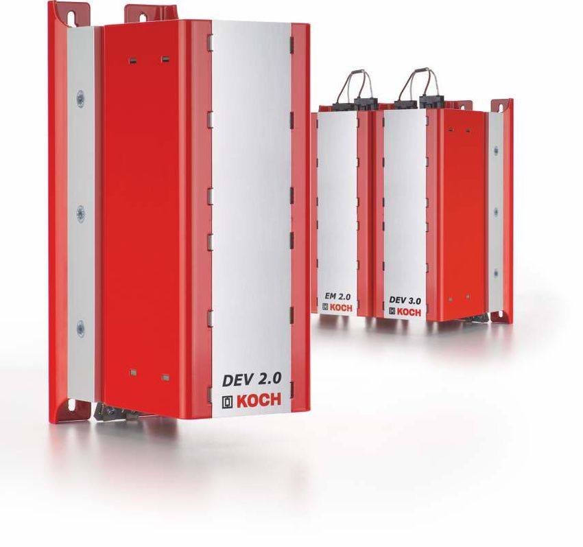
Managing
DC Link Energy

Dynamic
Energy Supply

DEV

Dynamic Energy Supply
DEV
With regard to electric energy, companies place particular importance on two factors: guaranteed supply and low prices. Both are called into
question with the implementation of the withdrawal of atomic energy. Broken down on electrical drives, power failures present a special challenge
even today in developed nations. With the Dynamic Energy Supply for converters and drive controllers short-term power failures can be bridged
and their consequences minimised.

Active supply module                           Short-term UPS for drives                                Gentle on the power grid and drives
for DC links                                   The Dynamic Energy Supply DEV acts as a                  The energy storage is charged after switching on
                                               short-term uninterruptable power supply for              the inverter for each charging routine, which acts
> for single and multiple axes systems
> no buttons, displays, other controls
                                               drives and servo controllers. The active                 very carefully not to overload the charging circuit
> provides support during power                capacity extension of the DC link of the                 and not to generate any negative circuit feedback
  failures or interruptions                    inverter stores an amount of energy that is              either.
> with a digital interface
                                               defined to the technical design. It serves to            The DEV is fully ready for use after only eight
                                               keep the voltage level of the DC link at a level         seconds. It then supports the DC link every time
                                               which bridges over the downtime without                  that its voltage falls below 470 VDC.
                                               trouble and/or brings the machine to a
                                               defined stop state in case of power failure.
                                               In each case, the objective is that the drive            With digital interface
                                               and all systems supplied by it either do not             The Dynamic Energy Supply DEV is equipped with
                                               perceive the power failure at all or are                 a digital interface with 24 Volt input. The
                                               brought into a defined state from which a                evaluation of the signal takes over the control of
www.brakeenergy.com/dev                                                                                 the machine just like the initiation of the
                                               restart is possible without any effort.
                                                                                                        established measures.

                                               Technical specifications DEV

                                               Parameter                                                                  Value
Installation dimensions
                                               Useful energy approx.                                                      2,000 Ws
and mounting-holes (mm)
                                               Continuous voltage of the DC link                                          800 VDC max.
                6.5                            Cycle time of use                                                          30 minutes
                                               Working voltage                                                            470 VDC (other possible)
         12

                                               Output                                                                     18 kW max.
                                               Digital interface                                                          24 VDC (for function monitoring)
    13                                         Built-in PTC discharge resistor                                            +
                      10

                                               Dimensions H x W x D                                                       300 x 100 x 201 mm
                                               Weight approx.                                                             6.9 kg
                                               Protection class                                                           IP 20

                                               Voltage curve of the DC link                             Support time according to power
                                               with DEV                                                 The time which a unit can support a given power with
                                                        without DEV                   with DEV          two Kilowatt seconds of energy can be read from the
                      280
                            300

                                                                                                        diagram. For x units, the support time is extended
                                                                                                        by x times.
                                               U[VDC]                                                       Support time [s]
                                                                                                        3

                                         UZK
                                                                                                        2

                                                                                                        1
                      10

     58±1 21
     100±1                                                            Power failure              Time   0           2          4   6   8   10    12     14      16      18

                                                                                                                                                      Power per 2kWs unit [kW]

2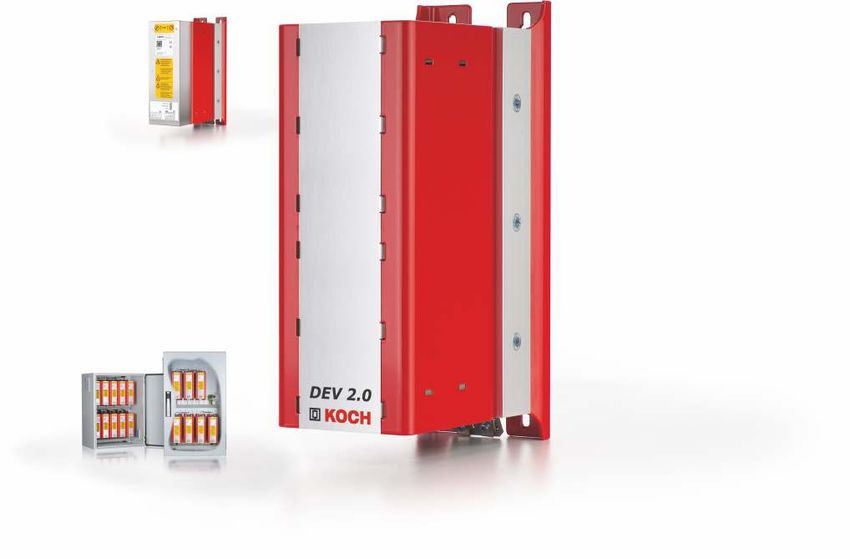
1, 2, 3

                                       4

                                                                                            1

                                                                                           2
                                                                                           3

Simple connection I (Bottom side)                    Simple connection II (Top side)
The DEV is extremely easy to connect                 1. Interface secured against polarity reversal for
with only two cables.                                   connecting extension modules and NEV
1. Negative terminal of the DC link                  2. Digital interface for function monitoring         The small built-in PTC braking
2. Discharge resistor                                3. Safety-relevant LED: Flashes, as long as the      resistor in the DEV serves as
                                                        storage unit is charged                           discharge resistor
3. Positive terminal of the DC link
4. Connection of the RS422 interface

The ideal addition to the DEV: NEV
The 24 Volt emergency power supply
ensures stable supply of a 24 V DC
network to be secured as an option
in combination with the DEV.
With at most 6 Amperes (150 VA),
the self-learning device is strong
enough to support control units and
other peripheral devices of the drive. Simply plugged into a
basic device and connected via plugs, the NEV keeps the 24
Volt appliance active even with voltage fluctuations or power
outages.

Control cabinet solutions
The Dynamic Energy Supplys required for the application are
also offered as equipped ready-to-assemble and prewired,
standardised control cabinets with the type designation KTS,
which can take on up to ten devices.

                                                                                                                                           3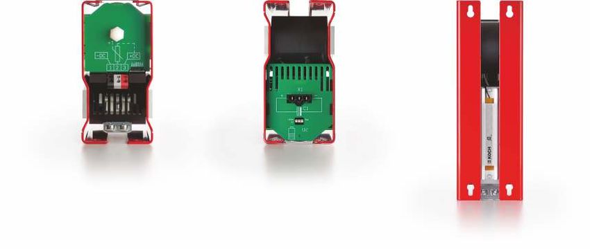
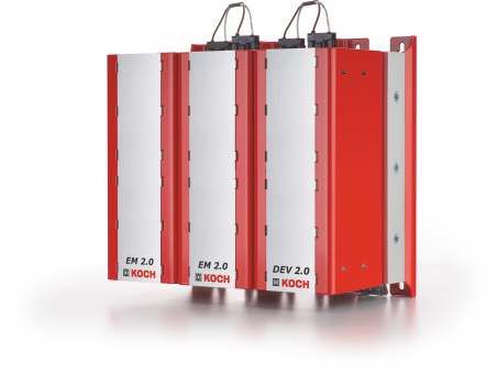
Extension module
DEV + EM
When the capacity storage of the Dynamic Energy Supply DEV is
insufficient extension modules can then be used. They can easily be
connected via the accompanying cables with reverse-polarity
protected plugs with the DEV. Done!

The storage is safely discharged via the discharge resistor built into the
extension modules before the connection. The number of connected
extension modules and thus the level of the stored energy is adapted
to the requirements of the application.

Storage extension                           Technical specifications
for the DEV
                                            Parameter                                                 EM 2.0A20                         EM 2.0A2020
> Multiplying the stored energy
> simple connection using plugs             Usable storage capacity approx.                           2,000 Ws                          4,000 Ws
> neither configuration nor                 Built-in PTC discharge resistor                           +                                 +
  commissioning effort                      Dimensions H x W x D                                      300 x 100 x 201                   300 x 100 x 201
> Discharge resistor on board               Weight approx.                                            4.1 kg                            6.2 kg
                                            Protection Class                                          IP 20                             IP 20

Accompanying energies can                   DEV + extension module
very easily be implemented
by the combinatorics with                   Required             Module               Space requirement/    Required            Module               Space requirement/
the extension modules                       energy       DEV      EM2.0       EM2.0      total width        energy       DEV     EM2.0     EM2.0        total width
                                            [kWs]        2.0B      A20        A2020        [mm]             [kWs]        2.0F     A20      A2020          [mm]
If the power of a DEV of max. 18 kW              2         1         0          0           100                 20        1         1         4           600
is not sufficient by itself, Dynamic             4         1         1          0           200                 22        1         0         5           600
Energy Storages can also be
                                                 6         1         0          1           200                 24        1         1         5            700
connected in parallel. The power is
multiplied according to the number               8         1         1          1           300                 26        1         0         6            700
of devices connected in parallel.               10         1         0          2           300                 28        1         1         6           800
                                                12         1         1          2           400                 30        1         0         7           800
                                                14         1         0          3           400                 32        1         1         7           900
                                                16         1         1          3           500                 34        1         0         8           900
                                                18         1         0          4           500                 36        1         1         8           1000
                                                                                                                38        1         0         9           1000

Simple connection I (Bottom side)                                                                                        Simple connection II (Top side)
Ground terminals                                                                                                     1   1. Reverse polarity protected interface to
                                                                                                                            connect to the DEV or from additional
                                                                                                                            extension modules and NEV
                                                                                                                     2   2. Central reverse polarity protected
                                                                                                                            interface. Discharge resistor
                                                                                                                         3. Safety-relevant LED: Blinks, as long as
                                                                                                                     1      the storage is still charged

                                                                                                                     3

4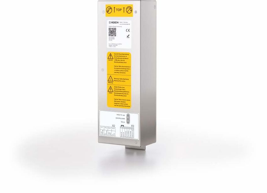
Dynamic Energy Supply
DEV 3.0
The DEV 3.0 is the first choice whenever the grid is too weak and the energetic support to the drive is      Active supply module
being required very often or rather cyclic e.g. in very short intervals. Based on the technical details of   for DC links
your individual application and combined with our know-how, we will find the perfect solution for
your requirements.                                                                                           > for single and multiple axes systems
                                                                                                             > no buttons, displays, other controls
                                                                                                             > provides support during power
                                                                                                               failures or interruptions

Technical specifications DEV 3.0

Parameter                                                          Value

Useful energy approx.                                              2,000 Ws
Continuous voltage of the DC link                                  800 VDC max.
Working voltage                                                    470 VDC (other possible)
Output                                                             18 kW max.
Built-in PTC discharge resistor                                    +                                         www.brakeenergy.com/dev3-0
Dimensions H x W x D                                               300 x 100 x 201 mm
Weight approx.                                                     6.9 kg
Protection class                                                   IP 20

The ideal addition to the DEV: NEV
The 24 Volt emergency power supply
ensures stable supply of a 24 V DC
network to be secured as an option
in combination with the DEV.
With at most 6 Amperes (150 VA),
the self-learning device is strong
enough to support control units and
other peripheral devices of the drive. Simply plugged into a
basic device and connected via plugs, the NEV keeps the 24
Volt appliance active even with voltage fluctuations or power
outages.

Control cabinet solutions
The Dynamic Energy Supplys required for the application are
also offered as equipped ready-to-assemble and prewired,
standardised control cabinets with the type designation KTS,
which can take on up to ten devices.

                                                                                                                                                 5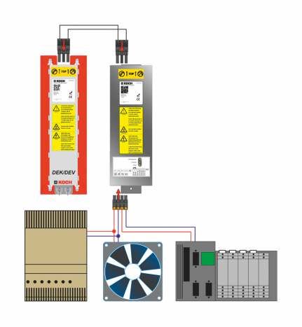
24 Volt Emergency Power Supply
NEV
The NEV is used to supply the 24 V DC circuit with mains independent electrical voltage. For this purpose, the NEV makes use of the energy of a
supply unit, namely the dynamic energy supply DEV or the dynamic energy storage combination DEK.
Under severe voltage fluctuations or when power fails, the NEV provides energy to its secured 24 volt circuit. The time depends primarily on the load
and the available energy from the supply unit. The settings of the supply unit also have an impact on the duration of the supply of electrical energy.
However, the NEV is not designed for continuous operation. The power supply that provides the continuous supply is normally connected as a
power source to the NEV. The consumers on the circuit to be secured are connected to the NEV. This is automatically used to teach The NEV about
the externally connected voltage and thus to support the voltage level.

Active 24-Volt support                           Technical Specifications NEV
power supply
                                                 Parameters                                                 Value
> space-saving
> without further manual                         Electrical power ratings
  configuration                                  Input voltage (terminal X2)                                22 VDC...26 VDC
> no keys                                        Rated current                                              6A (up to 150VA) for failure operation
> provides support when power                                                                               5A (up to 120VA) for mains operation
  failures or -interruptions occur
                                                 Standby power dissipation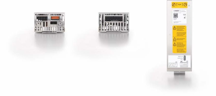
1
       1                                                       1        2

                                 2                                                                                2

                                 3

                                                                                                                  3
Simple connections I (bottom)                        Simple connections II (top)
1. Connection of external power supply and the       1. Reverse polarity secured interface to
   24-volt circuit (X2) that must be secured            connect the power supply unit (X1)
2. Signal terminals (X3)                             2. Reverse polarity secured interface to
3. Interface RS 422 (optional)                          connect another NEV (X1)                                  4

                                                     Labelling (front)
                                                     1. Installation position   2. Type label
                                                     3. Hazard notice           4. Pin assignment/device status

                                                     Wiring Diagram
5                                          1
                                                     1. NEV
                                                     2. Consumer, secured
                                                       22...26 VDC, max. 6 A (150 VA)
                                                     3. Consumer, unsecured
                                                     4. 24 V mains power supply
                                                     5. Power supply unit

                       4               3         2

Connect two or more NEV to a DEV / DEK, an EM
or a combination thereof
Several NEV units may also be connected to one unit or the combination by
using an extension. For this purpose, each additional NEV is connected by
means of connector X1 of the NEV using the connection cable.
No further EM may be connected to plug Xl of the NEV.
Important to note! The NEV-outputs must not be connected in parallel!
Ensure that no device is loaded with more than 6A/150VA.

                                                                                                                      7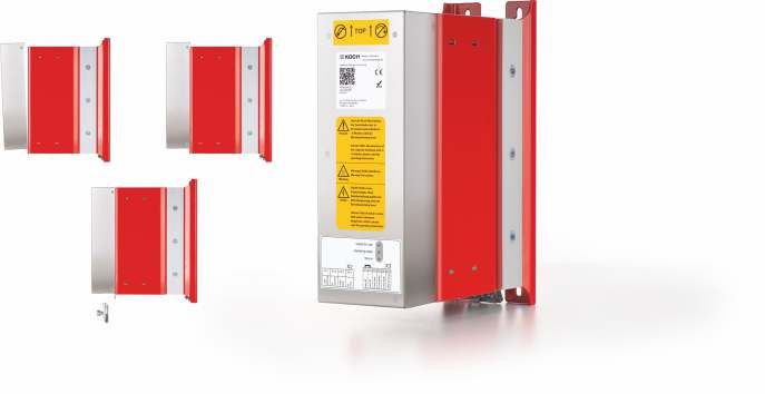
Managing DC Link Energy

Energy storage solutions and safe brake
                                                                     www.                   www.facebook.com/
resistors in wire-wound and PTC technology                      brakeenergy.com              michaelkochgmbh

We offer:

l Tested product quality
                                                                     blog.                   www.xing.com/
l Certified processes                                           bremsenergie.de                companies/
    – we undergo regular inspections by third parties                                       michaelkochgmbh

l Individual application support
    – owing to our modular system we can offer more
      than 60.000 solutions

l Machine-specific implementation                               www.newsletter.             www.youtube.com/
    – we match our products with your machines                  bremsenergie.de                   user/
                                                                                            MichaelKochGmbH
l High reaction rate
    – we provide you with a suitable offer
      in the shortest possible time

l Short delivery times
    – all components are in stock                                  Appstore                 www.linkedin.com/
                                                                                                company/
                                                                                            michael-koch-gmbh
l On-time deliveries every time
    – we deliver on schedule in optimal lot sizes

l Reliable partner
    – we strive for long-term business relationships

l Direct customer relationships
l www.brakeenergy.com

We look forward to
hearing from you!

       KOCH
Michael Koch GmbH, Zum Grenzgraben 28, D-76698 Ubstadt-Weiher                                     Qualitätsmanagement
                                                                                                  ISO 9001:2008
Phone (+49) 7251 / 96 26 20, Fax (+49) 7251 / 96 26 21                                             Regelmäßige freiwillige
                                                                                                   Überwachung

www.brakeenergy.com, mail@brakeenergy.com

Subject to technical changes. MK_PRO_DEV_ENG_R00_0                            D-138-00051
You can also read