Fabrication of Woven Honeycomb Structures for Advanced Composites
←
→
Page content transcription
If your browser does not render page correctly, please read the page content below

BAŞAL BAYRAKTAR G et al. Fabrication of Woven Honeycomb Structures... TEXT LEATH REV 1 (3-4) 2018 114-119.

Fabrication of Woven Honeycomb Structures for Advanced
Composites
Güldemet BAŞAL BAYRAKTAR*, Ata KIANOOSH, Derya BILEN
Ege University, Department of Textile Engineering, İzmir 35100, Turkey
*guldemet.basal@ege.edu.tr

Preliminary communication
UDC 677.074.1
DOI: 10.31881/TLR.2018.vol1.iss3-4.p114-119.a11
Received 24 October 2018; Accepted 27 November 2018

ABSTRACT
A honeycomb woven fabric was designed and produced on a sampling loom. After weaving cells in the fabric
were opened by polytetrafluoroethylene (PTFE) sticks and an epoxy resin was applied to fabric. For comparison
half of the fabric sample was impregnated with resin without opening the cells. Resulting fabric samples were
subjected to low-velocity impact test by using drop weight impact testing machine, CEAST Fractovis Plus –
7526.000. To evaluate the impact behaviour of the samples the contact force, contact time, deflection, and
absorbed energy values were recorded by data acquisition system (DAS). The energy absorbed by honeycomb
structure was around 7 Joule. The energy absorbed by flat sample, on the other hand, was too low and out of
the detection range of the testing equipment.

KEYWORDS
Honeycomb fabric, Reinforcement, Composite, Energy absorption

INTRODUCTION

Fibrous structures have been used extensively as preforms since they meet successfully the various require-
ments of composite reinforcements. In general, unidirectional and two dimensional (2D) laminated woven
structures are the main forms of reinforcement. Even though these 2D laminated woven structures have
been used with success for over 60 years, their use in many structural applications is limited due to their
high price as a result of labour intense manual lay-up process, their poor impact damage resistance, and
their delamination cracking under impact loading [1,2]. In order to overcome these limitations the devel-
opment of advanced 3D textile structures has gained great attention over the past 40 years. Advanced 3D
textile structures offer structural integrity and fibre continuity by providing multiaxial in-plane and out-of-
plane fibre orientation [3, 4].
One of the advance d 3D textile structures is 3D honeycomb structure. This structure has the geometry of a
honeycomb to allow the minimization of the material used to reach minimal weight and maximum strength.
Thus the composites reinforced with honeycomb structure are light weight, energy absorbent, and strong
[5, 6]. Chen et al. [7, 8] studied honeycomb fabrics and defined them based on the number of fabric layers
involved and the lengths of the free and bonded cell walls. A free cell wall is created by one layer of fabric.
A bonded cell wall is created by combining two adjacent fabric layers. By arranging the length of the free
and bonded cell walls the size of the cells can be adjusted. In another study, the mathematical modelling of

114 www.textile-leather.com
using the multilayer principle [9]. The 300 denier (335F96T) polyester filament yarn was used after
plied with a twist of 140 turns / meter. The fabric had four layers and the adjacent layers were
BAŞAL BAYRAKTAR
combined G et al.atFabrication
and separated arranged of Woven Honeycomb
intervals Structures...
(Figure 1). The peg plan TEXT LEATH
of the REV 1is(3-4)
weave given2018 114-119.
in Figure
2. The vertical lines indicate the heald shafts, and the horizontal lines indicate the wefts. Grey
honeycomb structurethat
squares represent wasthe
studied
healdand anwill
shaft algorithm was
be lifted created
during the for theinsertion.
weft computerized
Open design
spaces and manu-
between
facture of this type of fabrics [6].
layers allowed to obtain a 3D structure with honeycomb shaped cells in the cross-section with the
In this study a honeycomb woven fabric was designed and produced and the impact resistance of the
non-flat top and bottom surfaces.
composite structure reinforced by this fabric was determined.
Figure 1. Cell openings in honeycomb fabric design
Figure 1. Cell openings in honeycomb fabric design
EXPERIMENTAL
Production of Honeycomb Fabric
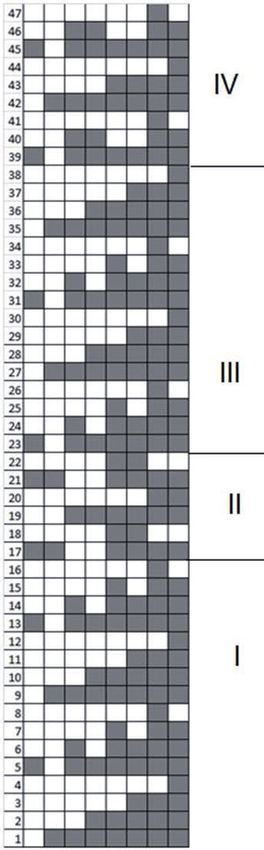
A honeycomb woven fabric was designed
and produced on a CCI Evergreen S8900
sample loom using the multilayer principle
[9]. The 300 denier (335F96T) polyester
filament yarn was used after plied with a
twist of 140 turns / meter. The fabric had
four layers and the adjacent layers were
combined and separated at arranged
intervals (Figure 1). The peg plan of the
weave is given in Figure 2. The vertical
lines indicate the heald shafts, and the
horizontal lines indicate the wefts. Grey
squares represent that the heald shaft will
be lifted during the weft insertion. Open
spaces between layers allowed to obtain
a 3D structure with honeycomb shaped
cells in the cross-section with the non-flat
top and bottom surfaces.
Production of Composite
The honeycomb fabrics are in a flat form
with close cells when they leave the loom
due to the nature of weaving. In order to
turn fabric into a 3D honeycomb struc-
ture polytetrafluoroethylene (PTFE) sticks Figure 2. Figure
Peg plan
2. Peg plan
Production of Composite
www.textile-leather.com 115
The honeycomb fabrics are in a flat form with close cells when they leave the loom due to the
nature of weaving. In order to turn fabric into a 3D honeycomb structure polytetrafluoroethylene
(PTFE) sticks were inserted into the top and bottom rows of the tunnels before impregnation (Figure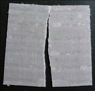
BAŞAL BAYRAKTAR G et al. Fabrication of Woven Honeycomb Structures... TEXT LEATH REV 1 (3-4) 2018 114-119.
GRUM GRUM
U, etal.
U, etal.
Influence
Influence
ofWeaveandDensities…
ofWeaveandDensities…
TEXTTEXT
LEATH
LEATH
REV 1REV
(1)12018
(1) 2018
1-11.1-11.
were inserted into the top and bottom rows of the tunnels before impregnation (Figure 3). Then, an epoxy
0 0
C for
resinCmix
90
for(FiberMak
minutes.
90 minutes.For For
comparison
Compositescomparison
F-1564somesome
Epoxyfabric
fabric
Resin were
andwere
impregnated
F-3486impregnated
with
Hardener) with
wasresin
resin
in flattened
applied toinboth
flattened
form
sides ofform
the
fabric
withoutusing
without aplacing
placingpaintbrush.
the sticks.Curing was carried out in an autoclave at 100 C for 90 minutes. For comparison
the sticks.
0
some fabric were impregnated with resin in flattened form without placing the sticks.
Figure 3A.Honeycomb fabric 3B. Fabric reinforced with PTFE sticks
FigureFigure
3A.Honeycomb
3A.Honeycomb
fabricfabric 3B. Fabric
3B. Fabric
reinforced
reinforced
with with
PTFE PTFE
stickssticks
Drop
Drop Weight
Drop
Weight Impact
Weight
Impact
ImpactTest
TestTest
The samplesThe Thewere
samples subjected
samples
werewere tosubjected
low-velocity
subjected impactimpact
to low-velocity testimpact
to low-velocity bytest
using
by drop
testusing weight
by using impact
dropdrop
weightweighttesti
impact ngtesting
impactmachine,
testing
CEAST Fractovis Plus – 7526.000. The impact tests were performed by using hemispherical steel impactor
machine,
machine,CEASTCEAST
Fractovis
Fractovis
PlusPlus
– 7526.000.
– 7526.000.
The The
impact
impact
teststests
werewere
performed
performed
by using
by using
hemispherical
hemispherical
tup of 12.7 mm diameter with a total mass of 5.02 kg. The maximum loading capacity of the impactor was
steel
22.4steel
impactor
kN. impactor
tup of
According tup
to12.7
of 12.7
ASTM mm mm
diameter
D3763, diameter
withwith
the clampeda total
a total
massmass
specimens of were
5.02
of 5.02
kg. The
kg. The
impacted maximum
maximum
with loading
impact loading
capacity
energy capacity
level of
of
10the
J of
at impactor
the
roomimpactor
was was
22.422.4
temperature. kN.
TheAccording
kN. According
test to ASTM
velocity to ASTM
was D3763,
1.99 D3763,
m/s. the clamped
the clamped
In order specimens
specimens
to evaluate thewere were
impactimpacted
impacted
behaviorwith
ofwith
the
samples,
impact
impact parameters
energy
energy ofsuch
levellevel10ofJas
atthe
10 J atcontact
room room force, contact
temperature.
temperature. time,
The The
test defl
test ecti
velocity
velocity
wason,was
and1.99
1.99 absorbed
m/s.m/s. energy
In order
In order values
to evaluate were
to evaluate
recorded by data acquisition system (DAS) during the impact test.
the impact
the impactbehavior
behavior
of the
of samples,
the samples,parameters
parameters
suchsuch
as the
as contact
the contactforce,
force,
contact
contact
time,time,
deflection,
deflection,
and and
absorbed
RESULTS absorbed
ANDenergy
energy
values
values
DISCUSSION werewere
recorded
recorded
by data
by data
acquisition
acquisition
system
system
(DAS)
(DAS)
during
during
the impact
the impact
test.test.
In this study a honeycomb woven fabric was produced using four layers. The resulting fabric cell has a height
RESULTS
RESULTS
of 6mm, ANDAND
free DISCUSSIONS
wall DISCUSSIONS
length of 5 mm, bonded wall length of 5 mm and an opening angle of 530 (Figure 4).
In this
In this
study
study
a honeycomb
a honeycomb
woven
woven
fabric
fabric
was was
produced
produced
usingusing
fourfour
layers.
layers.
The The
resulting
resulting
fabric
fabric
cell has
cell ahas
height
a height
of 6mm,
of 6mm,
free free
wallwall
length
length
of 5 of
mm,5 mm,
bonded
bonded
wallwall
length
length
of 5 of
mm 5 mm
and and
an opening
an opening
angle
angle
of 53of0 (Figure
530 (Figure
4 ). 4 ).
Figure 4 Cell size
Figure 4 Cell size
116 www.textile-leather.com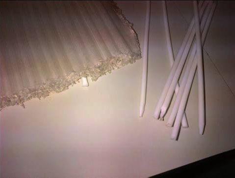
BAŞAL BAYRAKTAR G et al. Fabrication of Woven Honeycomb Structures... TEXT LEATH REV 1 (3-4) 2018 114-119.
Figure 4 Cell size
Figure 5. Honeycomb fabric
Figure 5. Honeycomb fabric
The fabric turned into a honeycomb composite by applying an epoxy resin mix (Figure 5). Before resin appli-
The infabric
cation cells turned
the fabric into
were a honeycomb
opened using PTFE composite
sticks. Halfbyofapplying
the fabricanwas
epoxy
left inresin
the flmix (Figure
attened form 5).for
comparison.
Before resinThen, the fabrics
application cellswere
in thesubjected to low
fabric were velocity
opened impact
using PTFEtest. In aHalf
sticks. honeycomb composite
of the fabric was leftstruc-
in
ture, the impact energy is absorbed not only by the elastic and plastic deformation of the fabric structure
the flattened form for comparison. Then, the fabrics were subjected to low velocity impact test. In a
but also the collapse of the cells. If the honeycomb structure cannot absorb the whole energy the force is
honeycomb composite structure, the impact energy is absorbed not only by the elastic and plastic
transmitted to structure underneath the composite and cause damage. Thus the energy absorbed by the
deformation
structure of cant.
is signifi the fabric
Figurestructure
6(a) shows but
thealso the collapse
composite of the
structure cells.
made If the
from the honeycomb
designed fabric structure
without
opening
cannot the cells.the
absorb Aswhole
seen from
energy thethefigure the
force is composite
transmittedstructure could
to structure not resist the
underneath the impact
compositeforce
andand
was broken apart. The test result was out of the detection range of the impact tester. Figure 6(b) shows
cause damage. Thus the energy absorbed by the structure is significant. Figure 6 (a) shows the
the composite structure made from the designed fabric with the open cells. The damage was restricted to
composite structure GRUM
made GRUM
U, etal.
theU,Influence
etal. Influence
ofWeaveandDensities…
ofWeaveandDensities…
TEXT LEATH
TEXT LEATH
REV 1 (1)
REV2018
1 (1)1-11.
2018 1-11.
a small area. Clearly, open cellfrom
structure designed
absorbed fabric
some of without
impactopening
energy. the cells. As seen from the
figure the composite structure could not resist the impact force and was broken apart. The test result
was out of the detection range of the impact tester. Figure 6(b) shows the composite structure made
from the designed fabric with the open cells. The damage was restricted to a small area. Clearly,
open cell structure absorbed some of impact energy.
a) Sample with closed cells b) Sample with open cells
a)sample
a)sample
with closed
with cells
closed cells b) Sample
b) Sample
with open
withcells
open cells
Figure 6. Fabric samples after impact test
Figure 6.
Figure
Fabric6.samples
Fabric samples
after impact
after impact
test test
Figure 7 shows the contact load–displacement plots of honeycomb composite structure with open cells
at 10Figure
J impact energy.
Figure
7 shows Thecontact
7 shows
the load–displacement
the contact curves plots
load–displacement show of
load–displacement anhoneycomb
increase
plots of the
of honeycomb load
compositeup structure
to a maximum
composite with load
structure with
termed
open peak
cells
open 10load,
atcells followed
Jatimpact
10 J impactbyenergy.
energy. aThe
drop afterload–displacement
the peak load.
load–displacement
The Thecurves
curves peak load
show an
show was 805ofN.the
increase
an increase The
of area
load
theup under
load a the
to up to a
curve gives the energy absorption. Calculated energy was 7,043 Joule. Unfortunately, close cell structure
maximum
maximum
load termed
load termed
peak load,
peak followed
load, followed
by a drop
by a after
drop the
afterpeak
the load.
peak The
load.peak
The load
peakwasload805wasN.805 N.
did not produce any results since the values measured were too low for the test equipment.
The area
The under
area under the curve
the curve
gives gives
the energy
the energy
absorption.
absorption.
Calculated
Calculated
energyenergy
was 7,043
was 7,043Joule. Joule.
Unfortunately,
Unfortunately,
close cell
closestructure
cell structure
did not
didproduce
not produce
any results
any results
since the
sincevalues
the values
measured
www.texti measured
were too
were117
le-leather.com too
low forlow
thefor
test
theequipment.
test equipment.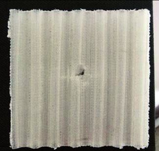
The area under the curve gives the energy absorption. Calculated energy was 7,043 Joule.
        Unfortunately, close cell structure did not produce any results since the values measured were too
BAŞAL BAYRAKTAR G et al. Fabrication of Woven Honeycomb Structures... TEXT LEATH REV 1 (3-4) 2018 114-119.
        low for the test equipment.

                             Figure 7. Load–displacement curve for low-velocity impact test
                                    Figure 7. Load–displacement curve for low-velocity impact test

CONCLUSION

This is a preliminary work to investigate the potential of honeycomb structures in advanced composites. In
this study we designed and produced a four layer honeycomb fabric as reinforcement material and inves-
tigate the impact resistance of the composite structure made from this preform with and without opening
the cells. The composite structure with closed cells did not resist the impact force and was broken apart.
The test equipment could not detect any signal. The hollow structure created by opening the cells, on the
other hand, resisted to impact force and absorbed an energy of 7,043 Joule. The test conducted in this study
was limited due to the time constrains. The further experiments and statistical analysis will be carried out
to found out the effect of impact site on results.
We believe that honeycomb structures have great the potential in advanced composites. Their properties
should be further explored. It is not difficult to weave this type of structure by a regular loom but opening
up cells is time consuming job. A simplified method would increase their usage.

Acknowledgements
The authors greatly appreciate the financial support provided by Ege University Research Foundation (Project
No: 17-MUH-056).

REFERENCES
[1]   Mouritz AP, Bannister MK, Falzon PJ, Leong KH. Review of applications for advanced three-dimensional
      fibre textile composites. Composites Part A: applied science and manufacturing. 1999 Dec;30(12):
      1445-1461.
[2] Hu JL. 3-D fibrous assemblies: properties, applications and modeling of three-dimensional textile
    structures. Cambridge (UK): Woodhead Pub. Ltd. in association with the Textile Institute; 2008. 7-8 p.
[3]   Cherif C. Textile materials for lightweight constructions technologies - methods - materials – properties.
      Berlin: Springer; 2016. 188-189 p.
[4] Behera BK, Hari PK. Woven Textile Structure. Cambridge (UK): Woodhead Publishing Series in Textiles;
    2010. 3-8 p.

118 www.textile-leather.com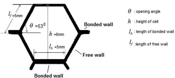
BAŞAL BAYRAKTAR G et al. Fabrication of Woven Honeycomb Structures... TEXT LEATH REV 1 (3-4) 2018 114-119.

[5] Chen X. Advances in 3D Textiles, Cambridge (UK): Woodhead Publishing Series in Textiles; 2015.
    104-130 p.
[6] Chen X, Ma Y, Zhang H. CAD/CAM for cellular woven structures. The Journal of the Textile Institute.
    2004 Jul;95(1-6):229–241.
[7] Chen X, Sun Y, Gong X. Design, manufacture, and experimental analysis of 3D honeycomb textile
    composites, part I: design and manufacture. Textile Research Journal. 2008 Sep;78(9):771–781.
[8] Chen X, Sun Y and Gong X. Design, manufacture, and experimental analysis of 3D honeycomb textile
    composites, part II: experimental analysis. Textile Research Journal. 2008 Nov;78(11):1011–1021.
[9] Takenaka K, Eiji S. Patent No. US5021283 - Woven fabric having multilayer structure and composite
    material comprising the woven fabric. 1988.

The paper presents a preliminary work on honeycomb woven structures for advanced composites, first
presented at the 8th International Textile Conference, Tirana, Albania, on October 18-19, 2018. Experimental
part of the study offered limited information. The paper presents a preliminary communication. Future
research will produce more results on top of which an original scientific paper will be published.

                                                                              www.textile-leather.com 119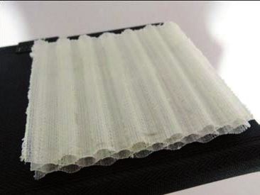
You can also read