Vibration Test on Existing Steel Sheet Pile - IOPscience
←
→
Page content transcription
If your browser does not render page correctly, please read the page content below

IOP Conference Series: Materials Science and Engineering

PAPER • OPEN ACCESS

Vibration Test on Existing Steel Sheet Pile
To cite this article: Sakhiah Abdul Kudus et al 2020 IOP Conf. Ser.: Mater. Sci. Eng. 713 012033

View the article online for updates and enhancements.

                               This content was downloaded from IP address 46.4.80.155 on 25/11/2020 at 06:55
The 2nd Global Congress on Construction, Material and Structural Engineering               IOP Publishing
IOP Conf. Series: Materials Science and Engineering 713 (2020) 012033 doi:10.1088/1757-899X/713/1/012033

Vibration Test on Existing Steel Sheet Pile

                     Sakhiah Abdul Kudus1, Kunitomo Sugiura2, Yasuo Suzuki3
                     1
                       Faculty of Civil Engineering, Universiti Teknologi MARA, 40450 Shah Alam, Selangor,
                     Malaysia.
                     2
                       Department of Civil and Earth Resources Engineering, Graduate School of Engineering, Kyoto
                     University, Kyoto, 615-8540, Japan.
                     3
                       Department of Civil Engineering, Faculty of Sustainable Design, University of Toyama,
                     Toyama, 930-8555, Japan
                     Corresponding author: sakhiah@uitm.edu.my

                     Abstract. A thorough understanding about the vibration of a structure is essential to resolve any
                     vibration problems. In this study, the vibration measurement was conducted on a real plate
                     structure, which is steel sheet pile. The monitored structures are located in Rokkenya-gawa river
                     and Aji-gawa river in Osaka City, Japan. The purpose of this investigation is to obtain
                     information about the overview conditions of this marine structure. A simple vibration
                     measurement as well as thickness measurement have been conducted. There is no serious
                     damage was observed on the monitored structure.

1. Introduction
The vibration characteristics needs to be understood first before any meaningful use in the field of
structural health monitoring. The applications of modal testing is a form of experimental evolution
conducted to determine the dynamic properties of a structure. In recent years, efforts have been made to
combine the modal testing with the analytical methods. Modal testing deals with a real structure directly,
and utilizes the analytical method to verify both methods. There are several methods applicable for
excitation of the structure and normally are pure random, burst random, period swept sine and hammer
impact. The use of hammer impact has a poor signal to noise ratio [1]. The dynamic characteristics of
the shaker may be combined with the test structure when the shaker is used to conduct modal testing.
Use of the dynamic properties of structure such as natural frequency and mode shape to evaluate the
damage has extensively been studied [2-5].
    Vandepitte and Olbrechts [6] studied the dynamic behaviour of the test structure when the structure
was excited by different excitation methods [6]. Three methods of excitation were considered: hammer
excitation; shaker with stringer excitation; and internal shaker excitation. The results obtained show that
the loading methods do influence the results obtained. Thus, the loading effect is one of the important
parameter to be considered. The study also concludes that the inertial shaker does not only add mass to
the system, but may also increase the stiffness of the complete system.
    In vibration analysis, free vibration is the natural response of a structure due to impact or
displacement. The responses obtain are based on properties of the structure and the vibration data
acquired from examination of the mechanical properties of the monitored structure. Structural vibration
is generally measured by an electronic sensor which converts the vibration motion into the electrical
signal. By analysing the signal, the nature of the vibration can be obtained. The dynamic measurements

              Content from this work may be used under the terms of the Creative Commons Attribution 3.0 licence. Any further distribution
              of this work must maintain attribution to the author(s) and the title of the work, journal citation and DOI.
Published under licence by IOP Publishing Ltd                          1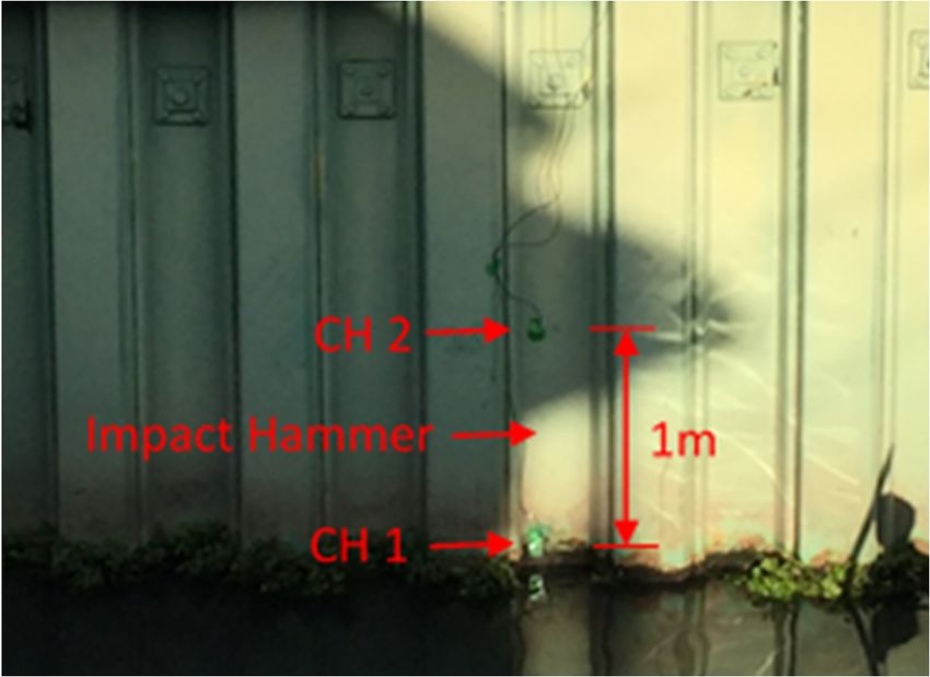
The 2nd Global Congress on Construction, Material and Structural Engineering               IOP Publishing
IOP Conf. Series: Materials Science and Engineering 713 (2020) 012033 doi:10.1088/1757-899X/713/1/012033

are normally conducted using an accelerometer, where the measurement of vibration response is
conducted by mounting the accelerometer to the surface of the structure.
   The damage assessment based on vibration technique was selected mainly due to merit of this
technique which have the ability to inspect large region in short time, low implementation cost, relatively
sensitive towards the local changes in the structure, low energy consumption and repeatability. This
study aimed to investigate the vibration characteristic of existing sheet pile exposed to marine
environment using vibration test.

2. Methodology
The use of corrugated plate for retaining walls and embankments has received worldwide acceptance
due to high strength, lower cost and ease of installation. Figure 1 shows the schematic diagram of the
steel sheet pile embedded in soil backfill. Normally, a steel tie rod is used to tie back the sheet pile. The
tie rod system is categorised as the most economical sheet piling tie back. The front side of steel sheet
pile was facing to the water river side while another side of steel sheet pile is facing to the backfield,
which indicates that the backside of this structure is inaccessible for any maintenance or inspection
work. The assessment of this type of structure is challenging because of limited access to the structure.
The steel sheet pile is only accessible on the river side, and the other side of sheet pile was embedded in
the backfill.

                 Figure 1. Schematic diagram of steel sheet pile embedded on backfill.

    Figure 2 summarizes the testing procedure for modal testing. Normally, the data from modal testing
is further analysed for estimation of frequency response function (FRF) to obtain other modal parameters
like mode shape and modal damping. A physical structure has an infinite number of mode shape together
with resonance frequencies. However, in this work, mode shape and modal damping were not possible
to be obtained from the vibration test conducted on steel sheet pile because of limited vibration
measurement. In order to obtain the mode shape and modal parameters of the monitored structure, large
number of discrete measurement response points need to be recorded on the surface of the structure. In
addition, improper selection of a discrete point where the measurement is conducted on nodal points
leads to inaccurate characterization of mode shape. The FRF is describe as the relationship between two
points in the input-output as a function of frequency.

                       Figure 2. Basic vibration measurement for modal testing.

                                                      2
The 2nd Global Congress on Construction, Material and Structural Engineering IOP Publishing
IOP Conf. Series: Materials Science and Engineering 713 (2020) 012033 doi:10.1088/1757-899X/713/1/012033
3. Results and discussion
The vibration measurement was conducted on a real plate structure, which is steel sheet pile. The
purpose of this investigation is to obtain information about the overview conditions of this marine
structure. A simple vibration measurement as well as thickness measurement has been conducted. Figure
3 depicts the site on the Aji-gawa river. The site visit was done on February 2016. The steel sheet pile
was used as permanent support. The thickness measurement was conducted on several points and the
losses of thickness is about 0.4 mm. The intact thickness of this wall is 10 mm. Thus, it can be concluded
that no serious corrosion damage happened here from the thickness measurement data table 1 and table
2 show details of the structure age and maintenance schedule on steel sheet pile located at Aji-gawa
river and Rokkenya-gawa river respectively. The structure is almost 50 years old but no serious damage
was observed. This was related to the properly scheduled maintenance provided by the authorized
authority.
Figure 3. The preliminary investigation of health condition of steel sheet pile
located at Aji-gawa river, Osaka.
Table 1. Construction and maintenance details of Aji-gawa river sluice water.
Year of construction 1970 (March)
Age of structure (during the inspection) 46 years
Type of plated structure Steel sheet pile
History of coating and/or painting 1998 and 2013
Galvanic protection 2018 (plan)
Others -
3The 2nd Global Congress on Construction, Material and Structural Engineering IOP Publishing
IOP Conf. Series: Materials Science and Engineering 713 (2020) 012033 doi:10.1088/1757-899X/713/1/012033
Table 2. Construction and maintenance details of Rokkenya-gawa river flood gate J1.
Year of construction 1969 (March)
Age of structure (during the inspection) 47 years
Type of plated structure Steel sheet pile
History of coating and/or painting 2013
Galvanic protection 2013
Others -
The vibration test was conducted using an impact hammer, vibration shaker and accelerometer. An
accelerometer is a simple mechanical device used in the engineering field to measure the acceleration
force. The force in this work is induced via vibration shaker and impact hammer. Figure 4 details the
location of excitation and the position of the accelerometer. Two accelerometers were placed in a fixed
position 1 m apart and excitation was made in the middle between the both of accelerometer. The
frequency of excitation varies from 50 Hz up to 400 Hz using the vibration shaker. Signal analysis can
be divided into time and frequency domain, and each domain provides a different view and insight into
the vibration.
Fast Fourier transform (FFT) is used to convert an original signal normally in the time domain to
representation in the frequency domain. Figure 5, Figure 6, and Figure 7 represent the frequency domain
data of the sheet pile when excited by the vibration shaker with frequencies of excitation of 50 Hz, 100
Hz and 150 Hz respectively. The analysis involves imposing excitation on the plate structure and
determining the frequency at which the structure resonates when the excitation and the vibration
response match. The data was captured by the accelerometer from Channel 1 located at the bottom part
of the sheet pile. From the results obtained, the peak of 66.47 Hz might represent one of the resonance
frequencies of this structure. In addition, the modal testing result for pile excited by the impact hammer
was presented in Figure 8. The pile was excited by several impacts. This section summarize how the
impact wave was generated and the vibration response obtained. In order to understand the vibration of
the structure, the steady vibration is necessary as compare to only one or small number of impacts. The
steady vibration can be induced from the actuator and vibrator.
Figure 4. The details of excitation and measurement point on steel sheet pile structure
located at Rokkenya-gawa.
4The 2nd Global Congress on Construction, Material and Structural Engineering IOP Publishing
IOP Conf. Series: Materials Science and Engineering 713 (2020) 012033 doi:10.1088/1757-899X/713/1/012033
2.00E-03
1.60E-03
Amp (m2/s)
1.20E-03
8.00E-04
4.00E-04 66.47
0.00E+00
0 50 100 150 200 250
Frequency (Hz)
Figure 5. The FFT result from accelerometer Channel 1 when the pile was
excited with frequency of 50Hz by shaker.
1.50E-03
1.25E-03
1.00E-03
Amp (m2/s)
7.50E-04
5.00E-04
2.50E-04
66.47
0.00E+00
0 50 100 150 200 250
Frequency (Hz)
Figure 6. The FFT results from accelerometer Channel 1 when the pile was excited
with frequency 100Hz by shaker.
5The 2nd Global Congress on Construction, Material and Structural Engineering IOP Publishing
IOP Conf. Series: Materials Science and Engineering 713 (2020) 012033 doi:10.1088/1757-899X/713/1/012033
1.20E-03
1.00E-03
8.00E-04
Amp (m2/s)
6.00E-04
4.00E-04
2.00E-04 66.47
0.00E+00
0 50 100 150 200 250
Frequency (Hz)
Figure 7. FFT result from accelerometer Channel 1 when the pile was excited with
frequency of 200Hz by shaker.
1.20E-03
1.00E-03
8.00E-04
Amp (m2/s)
6.00E-04
65.55
4.00E-04
2.00E-04
0.00E+00
0 50 100 150 200 250
Frequency (Hz)
Figure 8. The FFT results from accelerometer Channel 1 when the pile was excited
by impact hammer.
4. Concluding Remark
The appropriate usage of vibration testing in instrumentation and analysis benefits understanding of
problems in the structure. The important information related to structural characteristics including modal
parameter can be further obtained. Preliminary vibration tests have proven to be useful in the
optimization of methodology and equipment to be used for detailed investigation. Moreover, vibration
measurements give advantages to forecasting the extent of damage in a structure from modal parameters
obtained during analysis.
6The 2nd Global Congress on Construction, Material and Structural Engineering IOP Publishing
IOP Conf. Series: Materials Science and Engineering 713 (2020) 012033 doi:10.1088/1757-899X/713/1/012033
5. References
[1] Ma L and Peng X 2011 The study of excitation methods in experimental modal analysis of lightly
damped structures, Electric Information and Control Engineering (ICEICE) 2011
International Conference on Electric Information and Control Engineering
[2] Kudus S A, Suzuki Y, Matsumura M and Sugiura K 2018 Damage Assessment Based on Modal
Analysis of Pipe Structure Jurnal Teknologi 80(5) 37 - 44
[3] Kudus S A, Suzuki Y, Matsumura M, Sugiura K 2018 Vibration-response due to thickness loss
on steel plate excited by resonance frequency IOP Conference Series: Earth and
Environmental Science vol 140 (1) (United Kingdom: IOP Publishing) pp 012123
[4] Sakhiah B A K 2018 Study on Damage Assessment of Steel Plated Structures Based on Local
Vibration Characteristics PhD Thesis (Kyoto University)
[5] Kudus S A, Suzuki Y, Matsumura M and Sugiura K 2018 Damage Assessment Based on
Sensitivity of Modal Parameter in Plated Structure Malaysian Construction Research Journal
24(1) 65-82
[6] Vandepitte D V, Olbrechts T and Sas P 1997 FRF measurements errors caused by the use of
inertia mass shaker Proceedings of the 15th International Modal Analysis Conference pp 188-
194
7You can also read