Parametric Design Method Based on Grasshopper and Shoe Last Bottom Pattern Moulding Characteristics
←
→
Page content transcription
If your browser does not render page correctly, please read the page content below

IOP Conference Series: Materials Science and Engineering

PAPER • OPEN ACCESS

Parametric Design Method Based on Grasshopper and Shoe Last
Bottom Pattern Moulding Characteristics
To cite this article: Yujing Tian et al 2019 IOP Conf. Ser.: Mater. Sci. Eng. 520 012017

View the article online for updates and enhancements.

                                This content was downloaded from IP address 46.4.80.155 on 28/07/2021 at 19:21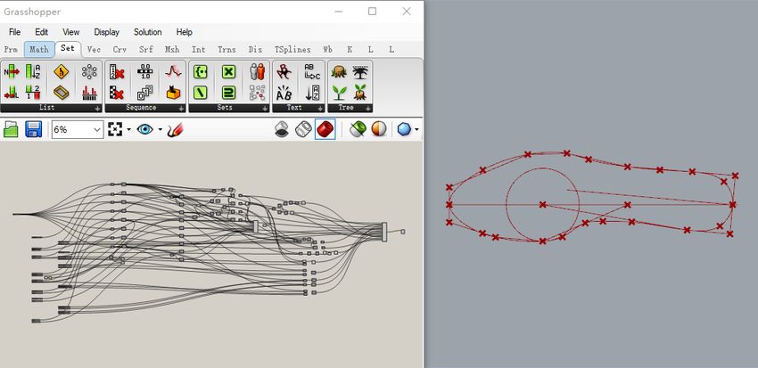
IC4M&ICDES                                                                                 IOP Publishing
IOP Conf. Series: Materials Science and Engineering 520 (2019) 012017 doi:10.1088/1757-899X/520/1/012017

Parametric Design Method Based on Grasshopper and Shoe
Last Bottom Pattern Moulding Characteristics

                     Yujing Tian1, Yuxin Miao1, Ying Yu1,* and Ziran Zhang2
                     1
                      Donghua University, Fashion and Design College, 200051 Shanghai, P.R. China
                     2
                      Shanghai University of Engineering Science, School of Art and Design, 201620
                     Shanghai, P.R. China

                     * yuyin513@163.com

                     Abstract. To adapt to the user's need for flexible and custom design of shoes, a more efficient
                     customization method is explored. Combined with the formation characteristics of the shoe last
                     bottom map, each characteristic parameter and related algorithm are analysed. Based on the
                     importance of the shape control, the feature parameters are graded. The parametric design
                     plug-in Grasshopper of Rhino software is used to construct the automatic moulding program of
                     the shoe last bottom to form a professional and feasible design method. Through the time
                     consumption comparison between the traditional method and the parametric design method,
                     the efficiency advantage is analysed, so as to truly improve the design and production
                     efficiency of the customized shoe last bottom.

1. Introduction
In the new age, people have had new and customized requirements for the shoes. How to design and
process shoes quickly and flexibly has become a problem urgently to be explored by every shoe
company[1]. Various custom design methods have also been developed that are used in all aspects of
shoe design. The design of the shoe last bottom is an integral part of the design and production of any
type of shoe, and its morphological features play an extremely important role in the aesthetics and
comfort of the final shoe. In the shoe last bottom design process, quickly producing various types of
shoe last bottom based on different needs has become the key to customization.
    Parametric design is a non-linear design method allows you to quickly generate different design
patterns by changing parameters in a visual programming language[2-3]. In the shoe last bottom
design process, looking for characteristic parameters and morphogenesis logic, combined with
parametric nonlinear thinking features, can effectively meet flexible design and production
requirements[4]. Based on the Rhino parametric design plug-in Grasshopper, this paper analyses the
forming characteristics of the last bottom, constructs the parameter logic, and forms a rapid
prototyping method for the customized base.

2. Parameter analysis of traditional last bottom moulding characteristics
The shoe last bottom is based on the foot shape, and the shape of the shoe last bottom must follow the
foot shape, so the design of the shoe last bottom is closely related to the parameters of the foot[5]. This
article takes the length of female standard shoes as 230 mm as an example to briefly introduce the
drawing steps of traditional shoe last bottom, as follows:

              Content from this work may be used under the terms of the Creative Commons Attribution 3.0 licence. Any further distribution
              of this work must maintain attribution to the author(s) and the title of the work, journal citation and DOI.
Published under licence by IOP Publishing Ltd                          1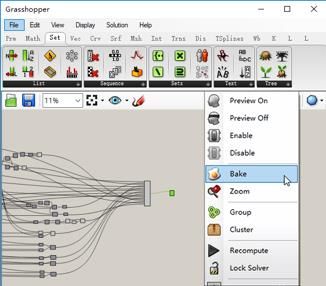
IC4M&ICDES                                                                                 IOP Publishing
IOP Conf. Series: Materials Science and Engineering 520 (2019) 012017 doi:10.1088/1757-899X/520/1/012017

2.1. Calculation of shoe last bottom moulding characteristic point data
Based on the length of the foot, the reference value of the formed feature point of the last bottom was
calculated from percentage relationship between foot length and parameters in national standards, it
can be adjusted based on the measurement data of the foot type and design style in customization,
including the length direction and the width direction, and a total of 16 related molded feature points
were obtained (Table 1).
  Table 1. Determination of last bottom moulding characteristic parameters of standard female shoe
                                       with a foot length of 230 mm.
                                                                                             Length
     Direction                  Parameter                         Calculation method          (unit:
                                                                                              mm)
                                                                   Measurement data
                               Foot length                                                     230
                                                                    (Known data)
                         Posterior tolerance point                 ≈Foot length *2%            4.5
                                Heel point                        ≈Foot length *18%            36.9
                               Waist point                        ≈Foot length *41%            89.8
                  The fifth metatarsal-phalange point            ≈Foot length *63.5%          141.6
      Length
                  The first metatarsal-phalange point            ≈Foot length *72.5%          162.3
     direction
                        Outer convex of little toe                ≈Foot length *78%           174.9
                         Outer convex of big toe                  ≈Foot length *90%           202.5
                                                                ≈Foot length – posterior
                              Toe endpoint                                                    225.5
                                                                        tolerance
                                                              Based on the design style, an
                           Last toe allowance                                                  16.5
                                                            intermediate value is given here
                           Heel overall width                                                   50
                            Waist outer width                Based on the national standard    32.5
                                                                reference data, it can be
                Fifth metatarsal-phalange outer width                                          43.9
                                                                 adjusted based on the
      Width      First metatarsal-phalange inner width                                         31.2
                                                              measurement data of the foot
     direction         Outer width of the little toe                                            43
                                                                 type in customization.
                        Inner width of the big toe                                             27.7
                                                              Based on the design style, an
                              Toe cap width                                                     30
                                                            intermediate value is given here

2.2. Measurement of length characteristic markers

                  Figure 1. Measurement of length characteristic markers (unit: mm).
   Draw a straight line as the bottom axis and measure the following dimensions on the shaft: OA, the
length of posterior tolerance is 4.5 mm; AB, the length of heel point is 36.9 mm; AC, the length of
waist is 89.8 mm; AD, the length of the fifth metatarsal-phalange point is 141.6 mm; AE, the length of
the first metatarsal-phalange point is 162.3 mm; AF, the length of the outer convex of small toe is
174.9 mm; AG, the length of the outer convex of big toe is 202.5 mm; AH, the length of toe end is
225.5 mm; HI, last toe allowance is 16.5 mm, as shown in Figure 1.

2.3. Measurement of width characteristic markers
With the above point as the standard, the vertical line of the axis is as follows: the upper and lower
parts of heel point are 25 mm, two points BB1, BB2, the full width of heel is 50 mm; CC', outer width

                                                    2
IC4M&ICDES IOP Publishing
IOP Conf. Series: Materials Science and Engineering 520 (2019) 012017 doi:10.1088/1757-899X/520/1/012017
of waist is 32.5 mm; DD', fifth metatarsal-phalange outer width is 43.9 mm; EE', first metatarsal-
phalange outer width is 31.2 mm; FF', outer width of the little toe is 43 mm; GG', Inner width of the
big toe is 27.7 mm, I1I2, toe cap width is 30 mm, as shown in Figure 2.
Figure 2. Measurement of width characteristic markers (unit: mm).
2.4. Determination of center line and heel width
The connection point of the branch line is determined by the equidistant relationship between the
width of the first and the fifth metatarsal-phalange outer width, and D'J = EE' is measured on DD' to
obtain the connection between points J and A. With A as the centre, the length of AB is the radius of
the arc, AJ is taken as B', and B' is taken as the vertical line of AJ, and the two sides are divided into
25 mm, and B'B'1 and B'B '2 are obtained. B’1 B’2 is the width of heel, move B'1 B'2 to point A to get
A1 A2, as shown in Figure 3.
Figure 3. Determination of centre line and heel width (unit: mm).
2.5. Curve connection after straight line connection
As shown in Figure 4, these lines connect E, B'2, A2, A, A1, B'1, C', D', F', I, I1, I2, G', E' and C and
the curve is connected to A, B'1, C', D', F', I, G', E' and B'2 based on the arrow, which is a female
standard shoe map with a foot length of 230 mm.
Figure 4. Curve connection after straight line connection.
3. Parametric logic construction based on Grasshopper
3.1. Hierarchical logic summary of characteristic parameters
Based on the importance level of the shape control of the parameter, the first level parameter, the
second level parameter and the third level parameter are shown in Table 2. The first level parameter
3IC4M&ICDES IOP Publishing
IOP Conf. Series: Materials Science and Engineering 520 (2019) 012017 doi:10.1088/1757-899X/520/1/012017
refers to the length of the foot, which is the basic parameter that should be determined first. The
secondary parameter is a key feature parameter that is extracted through the standard drawing process,
but it can actually be used to customize the shoe last bottom process. The measurements are modified;
the third level parameters are based on the secondary parameters, and morphological control points are
added for the morphological details to be used for the shape curve shape and the accuracy of the
customization process. The corresponding step is to connect the key feature points to the last bottom
curve in the shoe map. The shape of the connection curve is usually determined by the plotter's
personal data experience and line aesthetics, so there is some uncertainty. The third-level parameters
have no determined parameter values, and it is still necessary to adjust the curve by adjusting the
points of each position with a certain experience. The logic organization is as shown in Figure 5.
Table 2. Parameter variables required for last bottom pattern moulding with Grasshopper.
Level Parameter Effect
Overall foot length controlled for
Level 1 Foot length
different users
Percentage of posterior tolerance point
Percentage of heel point
Heel point width
Percentage of waist point
Waist outer width
Percentage of the fifth metatarsal-phalange point
Fifth metatarsal-phalange outer width
Characteristic point of last bottom
Level 2 Percentage of the first metatarsal-phalange point
pattern moulding
First metatarsal-phalange inner width
Percentage of outer convex of little toe
Outer width of the little toe
Percentage of outer convex of big toe
Inner width of the big toe
Allowance
Toe cap width
Control the shape of heel curve
Heel control point between posterior tolerance point
and heel point
Control the shape of heel curve
Outer heel anterior shape control point between outer heel point and
outer waist
Control the shape of heel curve
Inner heel anterior shape control point between inner heel point and first
metatarsal-phalange point
Control the shape of heel curve
Fifth metatarsal-phalange posterior shape
Level 3 between outer heel point and fifth
control point
metatarsal-phalange point
Control the shape of heel curve
First metatarsal-phalange posterior shape control
between inner heel point and first
point
metatarsal-phalange point
Control the shape of shoe curve
Outer shoe shape control point between outer convex of little
toe and toe cap
Control the shape of shoe curve
Inner shoe shape control point between outer convex of big
toe and toe cap
4IC4M&ICDES IOP Publishing
IOP Conf. Series: Materials Science and Engineering 520 (2019) 012017 doi:10.1088/1757-899X/520/1/012017
Figure 5. Level 1, 2 and 3 parameters.
3.2. Grasshopper edit input logic relationship
The above characteristic parameter parameters are logically coupled in combination with the moulding
process of the conventional shoe last bottom pattern. It includes the length calculation method and
shape connection method of each feature part. The bottom map is obtained based on the personal data
of the custom measurement. The basic operation method is used for the logic construction in the three-
parameter plug-in Grasshopper of the three-dimensional modelling software Rhino. During the
construction process, you’ll see the results immediately on the Rhino interface. The final logical
relationship between the program interface and the bottom graph is shown in Figure 6.
5IC4M&ICDES IOP Publishing
IOP Conf. Series: Materials Science and Engineering 520 (2019) 012017 doi:10.1088/1757-899X/520/1/012017
Figure 6. Grasshopper work interface and last bottom map.
3.3. Operation and inspection drawing effect
After modifying the shape of the curve by three levels of parameters to make the bottom map accurate,
the final bottom curve will be baked separately to the Rhino interface, and you can open the edit point
verification again, as shown in Figure 7. In order to facilitate the next 3D design and production of the
last bottom, the corresponding format can be derived based on different moulding software.
Figure 7. Bake the last bottom curve to Rhino in Grasshopper.
4. Comparative analysis of traditional and parametric last bottom drawing in shoe last bottom
customization
4.1. Brief description of traditional last bottom drawing of shoe last bottom customization
Based on the traditional personal shoe last bottom process, the traditional drawing process steps are as
follows:
(a) Measure the characteristic parameters of the target user's foot, including the foot length,
percentage of heel point, heel point width, percentage of waist point, waist outer width, percentage of
the fifth metatarsal-phalange point, fifth metatarsal-phalange outer width, percentage of the first
6IC4M&ICDES IOP Publishing
IOP Conf. Series: Materials Science and Engineering 520 (2019) 012017 doi:10.1088/1757-899X/520/1/012017
metatarsal-phalange point, first metatarsal-phalange inner width, percentage of outer convex of
little toe , outer width of the little toe, percentage of outer convex of big toe , inner width of the big toe.
(b) Determine the tolerance and width of the toe based on individual needs and styles.
(c) Based on the length of the foot, draw the bottom axis, and mark the position of the length
direction of each point from the axis based on the measurement data.
(d) Mark the position in the width direction of each point based on the measurement data.
(e) Determine the allowance and shoe cap width.
(f) Connect each feature point with a polyline and calculate the remaining feature points based on
the calculation.
(g) Connect each feature point with a smooth curve.
(h) Adjust the shape of the curve, curvature, etc. based on personal experience to make the shape
more smooth and accurate.
(i) Scan the image and import it into a computer, then draw a curve for further 3D production.
Use the program you have written to complete the Grasshopper parameter shoe persistent drawing
program. The steps to customize the personal basic map are as follows:
(a) Measurement parameters are the same as the conventional method.
(b) Determine the allowance and shoe cap width in the traditional method.
(c) The measurement data is directly input into the main and secondary parameters in the program,
and the initial bottom curve is automatically generated.
(d) Adjust the position of the third-level parameters to make the curve shape more accurate.
(e) Direct output curve for further 3D production.
Compared to the parametric design process, the traditional drawing process requires a nine-step
process, but the method of drawing the shoe bottom map is different. Due to the different experiences
of the painter, in order to avoid the influence of the artist's experience, this article invites an
experienced footwear primary student to use the above two methods for time-consuming comparative
experiments. Finally, it was found that in the process of customizing the last bottom, the measurement
of the characteristics of a single foot type is made to the production of an electronic version that can be
further used. The basic map, the cumulative time of the traditional method is about 45 minutes; the
parameterized bottom map method takes only 5 steps, about 11 minutes and 30 seconds, which greatly
shortens the time of customizing the new bottom as shown in Table 3.
Table 3. Comparison of time consumption between traditional and parametric drawing methods.
Traditional Parametric
Time
bottom bottom
consumption
drawing drawing
Measure the characteristic parameters of the target
5 min √ √
user's foot
Determine the allowance and shoe cap width 2 min √ √
Based on the foot length, determine the bottom
drawing axis, and mark the length direction of 5 min √ ×
each point in the axis based on measured data
Mark the width direction of each point in the axis
5 min √ ×
based on measured data
Determine the allowance and toe cap width 3 min √ ×
Connect each characteristic point with broken
lines and obtain the remaining characteristic 5 min √ ×
points based on the calculation
Directly input measurement data into the level 1
and 2 parameters in the program, automatically 2 min × √
produce the preliminary bottom curve
Connect individual characteristic points with
5 min √ ×
smooth curves
Adjust the curve shape, curvature based on 5 min √ ×
7IC4M&ICDES IOP Publishing
IOP Conf. Series: Materials Science and Engineering 520 (2019) 012017 doi:10.1088/1757-899X/520/1/012017
personal experience to make the shape smoother
and more accurate
Adjust the position of the level 3 parameters to
2 min × √
make the curve shape more accurate
Scan and import image into the computer, and
10 min √ ×
draw the curve for 3D production
Directly output curves for further 3D production 30 s × √
Cumulative time 45 min 11 min 30 s
5. Summary
Based on the moulding characteristics of the shoe last bottom and the parametric plug-in Grasshopper,
the drawing method greatly improves the efficiency and ensures the accuracy of the form. In the future,
individual foot parameters can be imported into actual production. The shoe last bottom is truly
customized to ensure personal comfort. Such a combination is a technological innovation with
commercial value, which will bring more possibilities for future shoe design.
Acknowledgments
Project Support by the Fundamental Research Funds for the Central Universities, Shanghai Style
Fashion Design &Value Creation Collaborative Innovation Center & the Fundamental Research Funds
for the Central Universities & Shanghai Summit Discipline in Design (DB18212).
References
[1] Pandremenos J, Georgoulias K, Chryssolouris G, Jufer N and Bathelt J 2016 a shoe design
support module towards mass customization Technology Management Conf. (Trondheim: IEEE)
[2] Dai X 2016 the application and exploration of parametric design used in product design based
on grasshopper Design 122-3
[3] Chen J 2015 Art J. 111-5
[4] He S and Liu B 2017 J. Mech. Eng. 53 118-27
[5] Mahmoodi-Rad A, Molla-Alizadeh-Zavardehi S, Dehghan R, Sanei M and Niroomand S 2015
Int. J. Adv. Manuf. Technol. 85 455-67
8You can also read